renray Healthcare Elite Bed Series User manual

Elite Bed
Range
Models:
E2000 - Elite Bed
E2000L- Elite Long Bed
E2060 - Elite Low Bed
E2060L- Elite Low Long Bed
E2400 - Elite Extra Wide Bed
Instructions For Use
IMPORTANT! Read the instructions in this booklet thoroughly before use

Page 1of 56
E200R IFU 2
1Introduction _______________________________________________________________ 2
1.1 Foreword _____________________________________________________________________ 2
1.2 Warning Symbols ______________________________________________________________ 3
2Intended Use ______________________________________________________________ 4
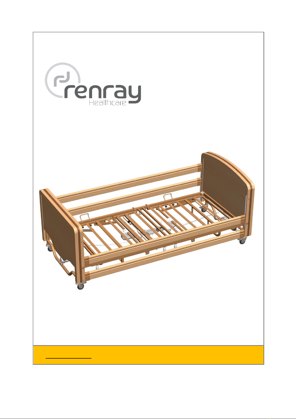
3General Description ________________________________________________________ 5
4Installation_________________________________________________________________ 6
4.1 Unpacking ____________________________________________________________________ 6
4.2 Supplied Parts Identification____________________________________________________ 6
4.3 Assembly Procedure___________________________________________________________ 9
5Care, Cleaning and Disinfection ___________________________________________16
5.1 Cleaning_____________________________________________________________________ 16
5.2 Disinfecting __________________________________________________________________ 17
6Operating Instructions _____________________________________________________18
6.1 General Safety Instructions ____________________________________________________ 18
6.2 Operator Safety Information __________________________________________________ 20
6.3 User Safety Information _______________________________________________________ 20
6.4 Handset Functionality_________________________________________________________ 21
6.4.1 Button Functionality______________________________________________________ 21
6.4.2 Locking the Handset _____________________________________________________ 22
6.5 Emergency Lowering Feature _________________________________________________ 22
6.6 Bed Tilt Feature _______________________________________________________________ 22
6.7 Manual Leg Section __________________________________________________________ 23
6.8 Castors ______________________________________________________________________ 24
6.9 Bed Extension ________________________________________________________________ 25
6.10 Emergency Lowering Facility __________________________________________________ 28
7Accessories ______________________________________________________________29
7.1 Available Accessories ________________________________________________________ 29
7.2 Mattress______________________________________________________________________ 30
7.3 Lifting Pole ___________________________________________________________________ 31
7.4 Side Rails_____________________________________________________________________ 32
7.4.1 Side Rail Locks ___________________________________________________________ 37
7.4.2 Extended & Extra Extended Side Rails _____________________________________ 38
7.4.3 Side Rail Height Extensions________________________________________________ 38
7.4.4 Side Rail Bumper Pads ___________________________________________________ 38
7.5 Fall Mat ______________________________________________________________________ 39
8Storage and Transport _____________________________________________________40
8.1 Assembling onto Transport Brackets ___________________________________________ 40
8.2 Storage & Transport Conditions________________________________________________ 43
9Troubleshooting ___________________________________________________________44
10 Technical Data ___________________________________________________________45
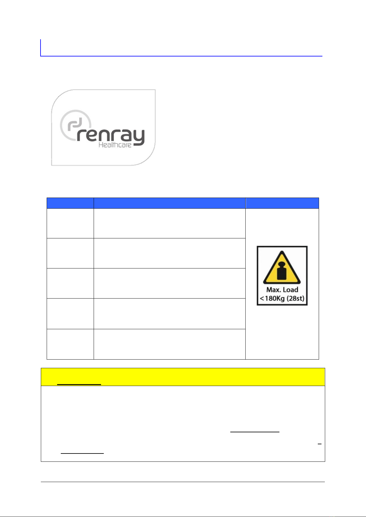
10.1 Safe Working Conditions ______________________________________________________ 45
10.2 Dimensions___________________________________________________________________ 45
10.3 Component Weights _________________________________________________________ 46
10.4 Electrical System Data ________________________________________________________ 47
11 Maintenance & Warranty __________________________________________________48
11.1 Maintenance ________________________________________________________________ 48
11.1.1 Routine Checklist ________________________________________________________ 48
11.1.2 Servicing ________________________________________________________________ 49
11.1.3 Spare Parts List___________________________________________________________ 49
11.1.4 Disposal of Electrical Equipment __________________________________________ 49
11.2 Warranty_____________________________________________________________________ 49
11.3 Contact Renray Healthcare___________________________________________________ 50
12 Appendix ________________________________________________________________51
12.1 Detailed Technical Description ________________________________________________ 51
12.1.1 Guidance & Manufacturer’s Declaration – Electromagnetic Immunity ______ 51

January 2015
Page 2of 56
1Introduction
1.1 Foreword
Thank you for purchasing a Renray
Elite Bed. In doing so, you have chosen a
quality Bed from a range which has been
designed to provide excellent functionality in
a safe manner.
To ensure the Elite Bed is always
operated correctly and safely please read
this document thoroughly and strictly follow
all the assembly, operating, cleaning and
maintenance instructions.
These instructions cover the following Bed models;
Model
Description
Maximum Load
E2000
Standard Elite Bed
Electrically operated bed, with adjustable
height, backrest and knee section.
Including mattress &
all fitted accessories
E2000L
Standard Elite Bed
As E2000, but with an increase in length of
115mm
E2060
Extra Low Elite Bed
As E2000, but with height adjustment from
20cm to 60cm from the floor.
E2060L
Extra Low Elite Bed
As E2060, but with but with an increase in
length of 115mm.
E2400
Extra Wide Elite Bed
As E2000, but with increased mattress width.
ALWAYS keep these instructions with the Bed for reference
Do ensure that you fully read & understand these Instructions for Use
Do ensure the Bed is assembled and installed in accordance with these
Instructions for Use
Ensure the Elite Bed is always used as intended, see 2 Intended Use, Page 4
Always ensure the Elite Bed is installed and commissioned as intended. (See 2
Intended Use, Page 4)

Page 3of 56
E200R IFU 2
1.2 Warning Symbols
WARNINGS given in this manual identify possible hazards in
procedures or conditions, which if not correctly followed, could result
in death, injury or other serious adverse reactions.
Cautions given in this manual identify possible hazards in procedures
or conditions, which if not followed, could result in equipment
damage or failure, and indicate moderate risk.
Electrical Hazard symbol indicates a hazard due to electrical voltage,
which if not correctly followed could result in death, serious injury or
fire.
Weight Hazard symbol appears when there is a potential weight
related hazard. This could be Bed or component weight, or a caution
about Patient/User weight or loading.
E2000
Specific Bed Model. Where a Warning, Caution or Hazard applies to a
specific model bed from the Elite range, it will be highlighted with the
addition of the Bed Model number appearing below the Warning
Symbol.

January 2015
Page 4of 56
2Intended Use
Each Bed in the Renray Elite Range is intended to assist members of staff in
Residential, Care and Nursing Homes to assist persons over the age of 12 years and
of a height in between 146cm - 185cm (4’9½” –6’1”) who have disabilities or need
care to compensate for an injury, handicap or disability. Persons outside of these
criteria will require additional risk assessment.
The Elite Beds are intended to be used by persons who are trained and fully
conversant with the Instructions for Use and how to operate the Bed and any fitted
accessories.
WARNING: DO NOT modify your Elite Bed, its components or any of its
accessories in any way; doing so could result a potential hazard.
If in any doubt, always ensure the patient has been Clinically Risk
Assessed as to their suitability before prescribing an Elite Bed and
mattress, including any accessories, in particular their size and
medical/mental condition.
The intended Safe Working Load (SWL) of all Elite Beds is 180Kg.
The Elite Beds should never be used on an uneven floor or an incline of
5° or greater.
The Elite Beds are not designed for use in hospitals.
The Elite Beds are designed for use only in the UK and Ireland.
The Elite Beds are not intended for use in the proximity of high-
frequency surgical equipment and/or defibrillators.
The Maximum Patient weight is 180Kg minus the combined weights of
all fitted accessories, up to a maximum of 150Kg. The weights for the
accessories can be found in 10.3, Component Weights, Page 46

Page 5of 56
E200R IFU 2
3General Description
The Elite Bed Range has been primarily designed as an electrically operated
bed to assist the Carer position the Patient and also to allow the Patient to adjust
their own position to aid their comfort.
The Bed is constructed from welded steel fabrications coated in protective
epoxy powder paint. The wooden head & foot panels cover the height adjustment
mechanisms at each end of the Bed.
E2000 illustrated
Foot End
Head End
Thigh Section
Calf Section
Head Section
Side Rail
Handset

January 2015
Page 6of 56
4Installation
Before you begin, you will need the following tools to assemble and disassemble
the bed;
1x Phillips Screwdriver
1x Pair of Scissors
4.1 Unpacking
Carefully open the boxes and unpack all components, laying all large
components flat.
Remove the cable ties securing the handset, cables and metal frames
together. Take care not to damage any electrical cables, and keep them tidy and
out of the way of the rest of the build procedure.
Before unpacking, be aware some of the larger assemblies &
components are heavy (See 10.3 Component Weights, Page 46). If
required, please take precautions before attempting to lift or move
any items.
Before the Bed is fully assembled, there are trapping hazards between
the movable sections of the Head and Foot decks. Pay attention to
where you grip the Decks, and always be aware of all movable parts.
4.2 Supplied Parts Identification
Once you have unpacked your Bed and are ready to assemble it, clear an
area of floor space where you will be able to access all four sides of the Bed. Also
take into account that you will need to tip the bed onto its side for access to the
underside of the mattress platform. Work on a suitably smooth/carpeted surface to
prevent damage to the bed, and if necessary cover the floor to protect it from dirt &
damage.
Before proceeding, apply the brakes to all four castors. This will prevent
unintended movement during assembly. (See 6.8 Castors, Page 24)
NOTE ►Before proceeding with the assembly, it is highly recommended that
you fully read through and understand all assembly instructions, and
make sure you have all necessary resources close at hand.
Before you begin any assembly, you should check you have all the following parts;

Page 7of 56
E200R IFU 2
Part Description/Name
Qty.
Head Deck Assembly*
1
Head End Assembly*
1
Foot Deck Assembly*
1
Foot End Assembly*
1
Deck Joining Bar
2
Hand wheel
8
Mattress Retainer Bracket**
4
Control Unit
1
Handset
1
Handset Lock-Out Key
1
Side Rail*
4
Side Rail End Caps (& Springs)
4
Side Rail Glides
4
Side Rail Lock Key***
1
Table 1 –Supplied Parts List
* Design/Type will vary depending on Bed model & options
** Dependent on Bed Model
*** Optional
NOTE ►There is a difference between the Head End and Foot End; The
‘prongs’ that locate the Mattress Platform onto the Head & Foot Ends
are longer on the Foot End. (See Figure 1 –Head & Foot End
Identification)
Head End - Shorter prongs,
with single notch in each
Foot End - Longer prongs, with
two notches in each
Figure 1 –Head & Foot End Identification (E2000 illustrated)

January 2015
Page 8of 56
Figure 2 –Part Identification (E2000 Bed illustrated)
* Appearance may differ depending on bed model
** Optional accessory
*** Dependent on Bed Model
Side Rails (x4)
Foot Deck*
Foot End*
Side Rail End Caps (x8)
(fitted with springs)
Handset &
Lock-Out Key
Mattress Retainer
Brackets (x4)***
Control Unit
Head End*
Deck Joining
Bars (x2)
Head Deck*
Hand
Wheels* (x8)
Side Rail Lock Key**
Side Rail
Glides (x4)

Page 9of 56
E200R IFU 2
4.3 Assembly Procedure
1
Once all unpacking steps have been
followed, you should have all the parts in
Figure 2 –Part Identification. If you do not
have the Transport Brackets, skip to Step 4
NOTE ►The largest bed sections may still
be assembled on the Transport Brackets. If this
is the case, follow Steps 2 & 3.
Each time the Bed is set up, specific attention must be drawn to
any potential dangers which can occur despite correct operation.
Before putting an Elite Bed into service for the first time, the
Instructions for Use must be read conscientiously and in detail by the
User / Care personnel.
2
12
3
Removing Bed from Transport Brackets
First clear the area you will be assembling
the bed in. Ensure there is an accessible
power socket close by.
Plan where the Head End will be
positioned.
Remove the Head Deck from the Transport
Brackets and place safely out of the way.
Then repeat this with the Foot Deck.
NOTE ►Always remove the Head Deck first, as this overhangs the bottom
mattress retainer of the Foot Deck (see picture 2, above, left)
3
Wheel the remaining Transport Assembly
so that the Foot End is next to a wall. Apply
the brakes to the Foot End and release the
hand wheels securing the Transport Brackets
to the Foot End. Separate the Head & Foot
Ends, leaving the Foot End resting in place
against the wall. Place the Head End safely
near its final location

January 2015
Page 10 of 56
4
a
b
c
d
Deck Frame Assembly
If you have not done so already, clear the
area you will be assembling the bed in. Ensure
there is an accessible power socket close by.
Plan where the Head End of the Bed will be
positioned.
Lay out the Deck parts, Mattress-side
down. Place the Head and Foot section near
their final positions.
Take the Deck Joining Bars, and identify
the locating tabs in them, (there may be a
long and a short end depending on model of
bed).
Insert one end of one of the Joining Bars
into the Foot Deck, and one end of the other
Joining Bar into the opposite side of the Head
Deck (see picture 4c, left.
Screw the hand wheels tight, ensuring the
Hand wheel screw locates in the locating tab
on each Bar.
Push the Head and Foot Decks together,
and ensure that the Locating Tabs line up with
the screw holes in the Head & Foot Deck.
Insert another two hand wheels and tighten
them, securing the Deck Sections together
(picture 4d).
Before proceeding;
Ensure all 4 central hand wheels are
tight, and that both Deck sections are
secured tightly against each other.
There should be none of the Deck
Joining Bars visible
Locating Tabs
Locating Tabs

Page 11 of 56
E200R IFU 2
5
Attach power cord to the Control Unit
Plug the power cable into the socket on the
reverse of the Control Unit as shown.
Secure it in place with the cover and 2x
screws (supplied)
(This step can be skipped if the control box
comes fitted with a power cable)
6
Remove the covers from the control unit
Locate the Control Unit, and identify the 2
bracket covers.
Release the two red lugs which secure the
covers
Slide the covers off the Control Box
7
Identify the Head & Foot Sections on the Control Unit (these are clearly labelled
on the housing, near to where the sliding covers are.
Image below shows location of Deck Identification markings highlighted in BLUE.
Foot
End
Head
End
8
a
b
Locate the Control Unit onto the two lugs
on the underside of the part-assembled
Mattress Platform. Ensure the lugs on Head
and Foot ends go into the corresponding slots
on Control Unit.
Slide the two bracket covers closed again,
locking the Control Unit to the Mattress
Platform.

January 2015
Page 12 of 56
c
Stand the Mattress Deck on its side, using
the head and knee sections to stabilise it.
These will fold out manually, without power.
d
Flip the Bed Deck onto its side and slide the 2
red tabs back into place to lock the Control
Unit onto the Bed.
Ensure both red tabs are inserted fully and
tight –if they will not slide, it may be that the
cover plate is not correctly centred.
9
Attach the Head and Foot Ends
Apply the brakes to the Head End, and tip
onto its side.
Insert the prongs of the Head End into the
Head Deck as far as they will go. Insert a Hand
wheel into either side of the Head Deck and
tighten the parts together. Ensure the Hand
wheel screw locates in the locating tab on
each bar.
Repeat the process for the Foot Deck.
NOTE ►The Foot Deck has 2 locating
tabs; use the tab nearest to the
castors unless you are using the
bed in its Extended
Configuration. (see 6.9 Bed
Extension, Page 25 for more
details)
The wooden panels that are recessed into either face of the Head &
Foot Ends are not designed to be load bearing, and precautions to
protect these surfaces should be taken during assembly.

Page 13 of 56
E200R IFU 2
10
a
b
c
d
e
Connect the Control Unit
a. Firstly, remove the screws holding the
cable retaining cover in place and
remove it.
b. Connect the Head End and Foot End
actuator cables to their corresponding
sockets on the Control Box.
Ensure that the Blank Connector is
present and connected. Removal of
this plug will disable the Control Unit.
c. Connect the Handset to its
corresponding socket on the Control
Box.
d. Replace the cable retaining cover and
screw it firmly into place. This will
prevent any accidental disconnection
of any cables from the control box.
e. Ensure that the power cord and
handset cables are not entangled with
any other cables or fittings, and then
loop them through the two strain relief
lugs on the top of the Control Unit.
Before proceeding, ensure that;
The cables are not excessively loose or
tight between the strain relief and
Control Unit.
Pulling on the cables does not pull on
the Control Unit connectors.
If possible, you can briefly connect the power
cable to a Mains outlet to test that all
functions operate correctly, then disconnect
from the Mains outlet before proceeding.
Remove screws
Remove screws
4) Head End
2) Foot End
3) Handset
1) Blank
Connector

January 2015
Page 14 of 56
Ensure that all cables are routed safely under the bed;
The Head and Foot End actuator cables should be routed as in
the illustration below, only going above the two bars highlighted
in RED
The Mains Cable and Handset Cable must not pass through any
parts of the Bed Deck.
11
a
b
Ensure all castor brakes are applied, and fold
the Head and Foot Deck sections back to the
flat position.
Carefully tilt the bed so it comes to rest on all
four castors. Walk around the Bed, and check
that all 8 hand wheels are still secure, and
that there is no excessive give between any
components.
12
a
Fit the Mattress Retainer Brackets
(Dependent on Bed model)
Loosen both of the thumbscrews on a
bracket until it easily fits over the edge section
of the movable section on the Head Deck.
Position it approximately 12 inches from the
top of the head section, so that the
uppermost part of the bracket should be flush
with the outside of the bed.

Page 15 of 56
E200R IFU 2
Always ensure the mains cable is kept tidy, and out of the way of any
obstructions or areas where it could pose a tripping hazard or become
damaged or cut.
b
Foot End Head End
Tighten the thumbscrews to secure the
Bracket in place until finger-tight. Do not force
them, as the brackets may deform.
NOTE ►The design of the mattress
retainer brackets may differ from illustration,
but they should always be fitted with the bent
wire component tilting away from the bed.
Repeat this process with each of the four
brackets. All 4 of the brackets are required to
ensure safe operation of the Bed.
The locations for each bracket are shown
in the illustration to the left; Two either side of
the Head Section, and two either side of the
Calf Section.
13
Manoeuvre the Bed to its final position, plug in and switch on the mains
supply. Check all movements correspond to those pictured on the Handset
buttons when operated. Install the Mattress, locating it into all 4 Mattress
Support Brackets, and the Foot Mattress Bracket. Finally, apply all 4 Castor
Brakes.
NOTE ►If there is no response, check the Handset is not ‘Locked Out’

January 2015
Page 16 of 56
5Care, Cleaning and Disinfection
Always clean the bed before use, in particular when assigning new
patients to reduce the risk of any possible cross infection.
Before beginning any cleaning or disinfecting procedure, make sure
you are wearing suitably protective clothing and gloves to prevent
against skin irritation or other adverse skin reactions.
Always dispose of cleaning agents in compliance with any instructions
given with the cleaning agent and facility policies.
Never use abrasive cleaning agents or pads on the bed, doing so will
damage the finish of the Bed.
If disinfection procedure involves large scale spaying of flammable
disinfectants, special precautions should be taken to prevent against
the risk of fire or explosion.
Always dispose of all cleaning agents & waste in accordance with
company procedures.
5.1 Cleaning
To clean the Bed;
Firstly, remove mattress and bedding, leaving only the Bed frame.
Use a soft cloth soaked in a solution of mild detergent and hot water to wipe
the bed clean. It is recommended to begin with the uppermost Bed surfaces,
and work systematically down towards the castors.
Wipe all surfaces of the Bed with sodium dichloroisocyanurate (NaDCC) at a
concentration of 1,000 parts per million (0.1%) of available chlorine using a
soft cloth.
Pay particular attention and care to areas where excess dust/dirt may have
gathered.
Wipe away any residue detergent solution using a soft cloth soaked in only
warm water, and dry with a paper towel or dry soft cloth.
Allow all cleaned parts to air dry thoroughly before replacing mattress and
bedding.
Always unplug the Bed from the main electricity supply before carrying
out any cleaning, disinfecting or maintenance on the Bed and keep
the plug away from all liquids.

Page 17 of 56
E200R IFU 2
Do not disconnect any cables between actuators, Handsets or the
Control Box; doing so could allow fluid ingress into electrical systems.
Never use any type of water or steam high pressure cleaner, jet or
spray on any of the electrical components, use detergent/disinfectant
on a damp cloth only.
5.2 Disinfecting
To disinfect the Bed;
Clean the Bed, as described in 5.1 Cleaning.
In cases where there has been contact with bodily fluids, e.g. blood, the
concentration of NaDCC should be increased to 10,000 parts per million (1%)
of available chlorine.
Dry with a paper towel or dry soft cloth
Allow all cleaned parts to air dry thoroughly before replacing mattress and
bedding.
Do not use phenol-based disinfectant solutions.

January 2015
Page 18 of 56
6Operating Instructions
6.1 General Safety Instructions
In order to avoid risk of crushing, always ensure there are no objects or
people’s limbs in any plane of movement of the Elite Bed before
operating or adjusting any Bed functions.
If the mental state, behaviour or other patient condition requires the
restricted use of Bed functionality, the Handset can be locked using
the Handset Lock-Out Key.
Bed adjustments must only be carried out by, or in the presence of,
suitably instructed and capable persons.
When using a Patient Hoist, or similar medical device to transfer
Patients to and from the Bed, always ensure there is adequate
clearance around and under the bed.
Always ensure the mains cable is disconnected from the wall socket
before attempting to move the Bed.
The mains cable exits the Bed from a point which will move during
normal operation. The cable must be free and unrestricted by any
furniture, objects, fasteners or walls and have sufficient slack in it to
allow full travel of the Bed from lowest to highest position without
becoming taught. Failure to do so can result in plug being pulled from
the wall, halting Bed operation, or in worst case cable strain resulting in
exposed electrical leads.
If either the plug or mains cable becomes damaged, switch off and
unplug the Bed from the electricity supply. Do not use again until the
full mains cable and plug have been replaced by the manufacturer or
other authorised service personnel.
Never obstruct access to the Mains Plug, or locate the Mains Plug in
such a way that it could not easily be disconnected in event of an
emergency.
To isolate the Elite Bed from the mains 240V electricity supply, switch off
at the wall socket & remove the plug from the wall. To isolate the unit
completely, also disconnect the batteries for the Emergency Lowering
Feature (See 6.10 Emergency Lowering Facility, Page 28)
Before moving the Bed, set the mattress platform in its lowest horizontal
position before disconnecting from the mains supply, and then
disengage all four castor brakes.
The assembled Elite Bed is heavy when assembled. Be aware of this,
and the damage it can cause to people and its surroundings when
being moved.

Page 19 of 56
E200R IFU 2
Never use the Bed in the presence of explosive or flammable gasses,
such as may be present in anaesthetic agents.
NEVER attempt to use an Elite Bed to transport Patients.
Always ensure that the underneath of the Bed is kept clear at all times.
Ensure the operation and movement of the Bed is never impeded by
any obstacles such as bedside furniture, electrical sockets, skirting
boards or other fixtures & fittings.
ALWAYS take care when adjusting the Bed, and check beneath the
Bed for obstructions, children, confused adults or other hazards each
time before operating the Bed.
E2060
The Elite Low Bed (E2060) can achieve a much lower mattress height
than the Standard Elite. As such greater care & attention needs to be
paid to objects in close proximity to the Bed.
Do not allow children to play with or under the Bed at any time.
Renray Elite Beds need special precautions regarding EMC and needs
to be installed and put into service according to the EMC information
provided in the Appendix; 12.1.1 Guidance & Manufacturer’s
Declaration –Electromagnetic Immunity, Page 51.
Whilst the electrical equipment fitted to this Bed has been tested
according to;
IEC 60601-1-2:2005 Medical Electrical Equipment - Pt 1-2
IEC 61000-3 EMC - Pt 3-2
IEC 6100-3-3 am1, EMC - Pt 3
Please check that other equipment used in the vicinity of this bed
does not pose any reciprocal interference during specific
investigations or treatments.
Portable and mobile RF communications equipment can affect
Renray Electric Bed.
The use of accessories, transducers and cables other than those
specified with the exception of transducers and cables sold by the
manufacturer of Renray Elite Beds as replacement parts for internal
components, may result in increased emissions or decreased immunity
of the Elite Bed.
Do not continue to use the Bed if you notice any unusual noises, smells
or any components becoming excessively hot.
This manual suits for next models
10
Table of contents
Popular Mobility Aid manuals by other brands

NRS Healthcare
NRS Healthcare L97986 User instructions

Vitea Care
Vitea Care AMBONA Instructions for use

ADAPT SOLUTIONS
ADAPT SOLUTIONS XL-SEAT installation manual

Invacare
Invacare Actio 2 P550/2 user manual

Eurovema
Eurovema Volaris Compact user manual

Sunrise Medical
Sunrise Medical GEMINO 20 S user manual