REPLIGEN OPUS 14 User manual

OPUS® 5 - 80R
Pre-packed Chromatography Columns
USER GUIDE

The information contained in this document is subject to change without notice.
Repligen Corporation makes no warranty of any kind with regard to this material, including, but not
limited to, the implied warranties of merchantability and fitness for a particular purpose.
Repligen Corporation shall not be liable for errors contained herein or for incidental or
consequential damages in connection with the furnishing, performance, or use of this material.
No part of this document may be photocopied, reproduced, or translated to another language
without the prior written consent of Repligen Corporation.
For further information, please contact Repligen Corporation at www.repligen.com.
© 2018 Repligen Corporation. All rights reserved.
The trademarks mentioned herein are the property of Repligen Corporation and/or its affiliate(s) or
their respective owners.
Customer Support
customerserv[email protected]om
+1-781-250-0111
Repligen Corporation
41 Seyon Street Building #1, Suite 100
Waltham, MA 02453
www.repligen.com

Table of Contents
1Safety Notices ......................................................................................................................4
2Introduction .........................................................................................................................4
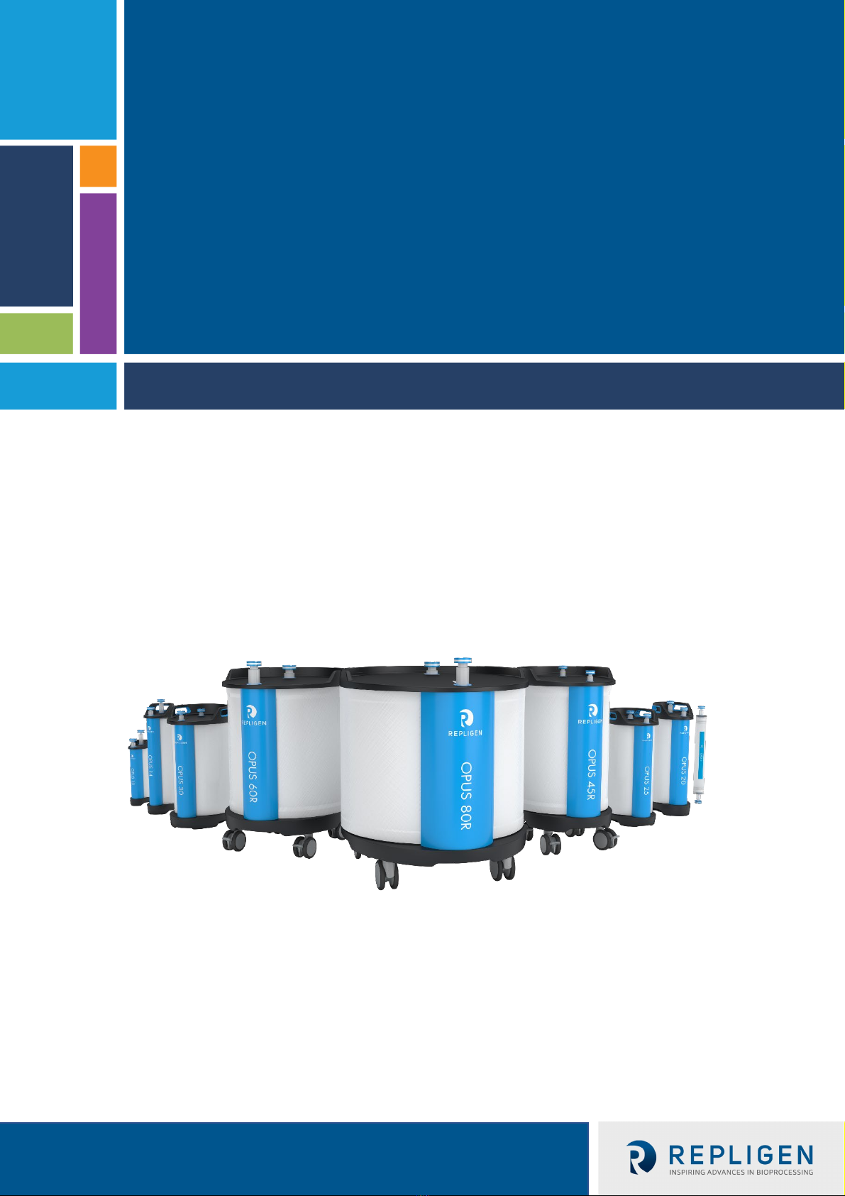
2.1 What is Open Platform User Specified (OPUS®)? ......................................................................4
2.2 Column Design ...........................................................................................................................4
2.3 Platformable ..............................................................................................................................5
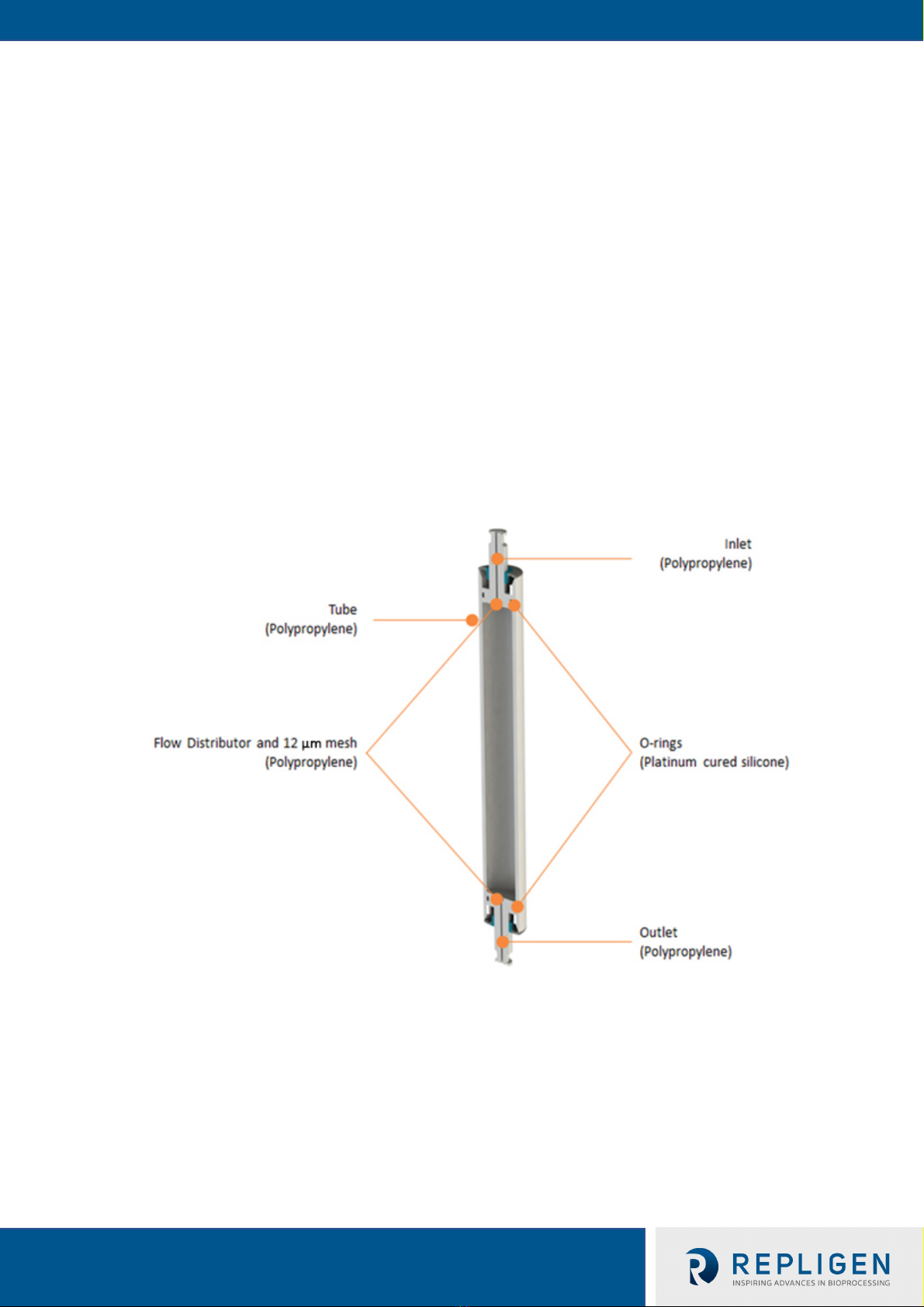
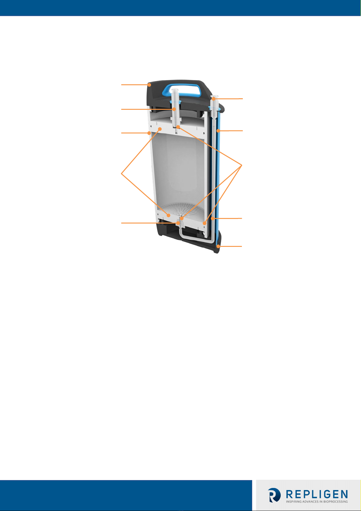
2.4 Materials of Construction ..........................................................................................................5
2.5 OPUS® Physical Specifications ...................................................................................................7
2.6 Product Contact Materials.........................................................................................................8
2.7 Solvent Compatibility.................................................................................................................9
2.8 Column Mass Table..................................................................................................................10
2.9 OPUS® Column Handling..........................................................................................................10
3Preparing to Use Your OPUS® Column .................................................................................10
4OPUS® Column Sanitization, Storage, and Disposal.............................................................. 13
4.1 Cleaning and Sanitization Notes ..............................................................................................13
5Troubleshooting .................................................................................................................13
5.1 Air in the column......................................................................................................................13
5.2 High pressure during first use of column.................................................................................13
5.3 Pressure increase during run ...................................................................................................14
5.4 Pressure drop during run .........................................................................................................14
6Appendices.........................................................................................................................15
6.1 Appendix 1: Use of a 3-Way Valve for Inlet Connection and Air Purging................................15
6.2 Appendix 2: Connecting an OPUS® column to Chromatography Skids ...................................16
6.3 Appendix 3: Column Performance Testing ..............................................................................16
Index .........................................................................................................................................19

List of Tables
Table 1. Removal of OPUS®Pre-packed Columns from Packaging.........................................................4
Table 2. Physical Specifications Summary (OPUS® 5 – 30 Columns) ......................................................7
Table 3. Physical Specifications Summary (OPUS® 5 – 30 Columns) ......................................................8
Table 4. Product Materials and Quality Standards .................................................................................9
Table 5. Solvent Compatibility for OPUS® Columns................................................................................9
Table 6. Approximate Column Weight..................................................................................................10
Table 7. Column Handling Features......................................................................................................10
List of Figures
Figure 1. Materials of Construction Summary: OPUS® 5 and 8 Columns ...............................................5
Figure 2. Materials of Construction Summary: OPUS® 10 – 30 Columns ...............................................6
Figure 3. Materials of Construction Summary: OPUS® 45R, 60R, and 80R Columns..............................7
Figure 4. SaniSure Clamp Removal .......................................................................................................11
Figure 5. Stainless Steel Valve Connection to OPUS® Column..............................................................11
Figure 6. Position of 3-way valve for purging air from the column inlet..............................................15
Figure 7. 3-way valve for flow to column..............................................................................................15
Figure 8. Absorbance / Conductivity Graph..........................................................................................17

UG-OPUS® 5-80R
4
OPUS® 5-80R Pre-packed Chromatography Columns
Safety Notices1
Please abide by the following movement and handling recommendations according to uncrating
guide based on column internal diameter.
Do not pull or strain the white inlet and outlet ports protruding from the top of the OPUS® column.
Table 1. Removal of OPUS®Pre-packed Columns from Packaging
•Unless otherwise specified by the end-user, OPUS® pre-packed columns are generally
shipped in 20% Ethanol solution, a recognized bacteriostatic agent. Consult the Certificate
of Analysis (CoA) or Certificate of Quality (CoQ) for confirmation of storage solution
•Follow all local regulations for safe disposal
•For laboratory and manufacturing production use only
•Not for administration to humans
Introduction2
2.1 What is Open Platform User Specified (OPUS®)?
Open Platform User Specified (OPUS®) Columns are designed to perform chromatography
purification of biological molecules in either GMP or non-GMP applications.
The OPUS® Pre-Packed Column platform offers an alternative to conventional “pack in place” glass
or stainless steel columns and can be reliably packed with virtually any resin from any source. To
accommodate a wide range of biopharmaceutical applications, OPUS® Columns are configurable for
nearly any bed height and industry standard internal diameters.
2.2 Column Design
The OPUS® platform has been designed to meet the requirements of GMP manufacturing in the
pharmaceutical and biopharmaceutical industries for campaign-use and single-use applications.
Column Size Instruction
OPUS® 5 - 14 Columns
•
Use two hands to grab the column and lift it from the box
•For OPUS®14 columns, one handle is provided on the top cap
with additional hand holds on the bottom cap
OPUS® 20 – 30 Columns
•Use two people to grab one handle each
•Lift the column slowly up from the box
•Place it carefully onto the floor or cart. LIFT BY THE HANDLES
ONLY
OPUS® 45R – 60R Columns
•Roll out the column from the wooden crate with the help of
attached casters and ramp
OPUS® 80R Columns
•Roll out the column from the wooden crate with the help of
attached casters and ramp
•Two or more individuals are required to roll the column out
from the crate and about the facility

UG-OPUS® 5-80R
5
OPUS® 5-80R Pre-packed Chromatography Columns
2.3 Platformable
OPUS® Columns are designed to be broadly configurable to accommodate a wide range of
purification and polishing applications for vaccines, monoclonal antibodies, and recombinant
proteins. For example, OPUS® Columns:
•Accept nearly all commercially available bioprocessing resins
•Available in a wide range of bed heights and industry standard column diameters
•Configurable for specific packing procedures, release tests, and storage solutions
Regulatory Support File
For additional details into supporting data for the design of the OPUS® product line and testing of
qualified processes, refer to the Regulatory Support File (RSF). The RSF may be accessed via
Repligen website.
2.4 Materials of Construction
Figure 1. Materials of Construction Summary: OPUS® 5 and 8 Columns

UG-OPUS® 5-80R
6
OPUS® 5-80R Pre-packed Chromatography Columns
Figure 2. Materials of Construction Summary: OPUS® 10 – 30 Columns
Inlet Port
(Polypropylene)
Top Cap
(ABS Plastic)
Outlet Port
(Polypropylene)
Column Tube
(Polypropylene)
Flow
Distributors
with 12μm
Mesh
(Polypropylene)
Column Outlet
(Polypropylene)
Bottom Cap
(ABS Plastics)
Return Line
(Platinum
Cured Silicone)
Side Guard
(ABS Plastic)
O-rings
(Platinum
Cured Silicone)

UG-OPUS® 5-80R
7
OPUS® 5-80R Pre-packed Chromatography Columns
Figure 3. Materials of Construction Summary: OPUS® 45R, 60R, and 80R Columns
2.5 OPUS® Physical Specifications
Table 2. Physical Specifications Summary (OPUS®5 – 30 Columns)
Column Diameter
Physical
Attributes 5.1 cm 8.1 cm 10 cm 12.6 cm 14 cm 20 cm 25 cm 30 cm
Internal Cross
Section 20.4 cm251.5 cm278.5 cm2125 cm2154 cm2314 cm2491 cm2707 cm2
Column Body
Pressure Rating 4 Bar 4 Bar 4 Bar 4 Bar 4 Bar 4 Bar 4 Bar 4 Bar
Bed Height
Range
5 – 30
cm
5 – 30
cm
5 – 30
cm
5 – 30
cm
5 – 30
cm
5 – 30
cm
5 – 30
cm
5 – 30
cm
Column Volumes
10 cm Bed
Height
20 cm Bed
Height
30 cm Bed
Height
0.2 L
0.4 L
0.6 L
0.5 L
1.0 L
1.5 L
0.8 L
1.6 L
2.4 L
1.3 L
2.5 L
3.8 L
1.5 L
3.1 L
4.6 L
3.1 L
6.3 L
9.4 L
4.9 L
9.8 L
14.7 L
7.1 L
14.1 L
21.2 L
Assembled
Column Height
~20 cm
+ bed
height
~20 cm
+ bed
height
~20 cm
+ bed
height
~28 cm
+ bed
height
~30 cm
+ bed
height
~30 cm
+ bed
height
~33 cm
+ bed
height
~35 cm
+ bed
height

UG-OPUS® 5-80R
8
OPUS® 5-80R Pre-packed Chromatography Columns
Column Diameter
Outer Diameter
(including caps) 7 cm 10 cm 16 cm 20 cm 21 cm 27 cm 33 cm 38 cm
Inlet/Outlet
Flow Path
Internal
Diameter
3.45 mm
5/32
inch
4.57 mm
3/16
inch
6.35 mm
1/4 inch
6.35 mm
1/4 inch
6.35 mm
1/4 inch
6.35 mm
1/4 inch
9.53 mm
3/8 inch
9.53 mm
3/8 inch
Inlet and Outlet
Port Connectors
3/4 inch
mini
Tri-
Clamp
3/4 inch
mini
Tri-
Clamp
3/4 inch
mini
Tri-
Clamp
3/4 inch
mini
Tri-
Clamp
3/4 inch
mini
Tri-
Clamp
3/4 inch
mini
Tri-
Clamp
3/4 inch
mini
Tri-
Clamp
3/4 inch
mini
Tri-
Clamp
Table 3. Physical Specifications Summary (OPUS®5 – 30 Columns)
Column Diameter
Physical Attributes 45.7 cm 59.9 cm 79.9 cm
Internal Cross Section 1,640 cm22,818 cm25,014 cm2
Column Body
Pressure Rating 3 Bar 3 Bar 3 Bar
Bed Height Range* 5 – 30 cm 5 – 30 cm 10 – 30 cm
Column Volumes
10 cm Bed Height
20 cm Bed Height
30 cm Bed Height
16 L
33 L
49 L
28 L
56 L
84 L
50 L
100 L
150 L
Assembled Column Height
(cm)^
≤ 22 cm BH: ~90 cm
>22 cm BH: ~116 cm
≤ 22 cm BH: ~93 cm
>22 cm BH: ~120 cm
≤ 20 cm BH: ~97 cm
>20 cm BH: ~123 cm
Outer Diameter (including
caps) 54 cm 68 cm 91 cm
Inlet/Outlet Flow Path
Internal Diameter
12.7 mm
1/2 inch
19.1 mm
3/4 inch
19.1 mm
3/4 inch
Inlet and Outlet Port
Connectors
Per ASME BPE Standards,
Current Edition
3/4 inch
mini Tri-Clamp
1 inch
Tri-Clamp
1 inch
Tri-Clamp
*Resin Recovery design columns have a minimum bed height of 10 cm.
^These values are estimates based on the target bed height (BH) of the column.
2.6 Product Contact Materials
OPUS® 5 – 80R Columns are designed using polymers which are best suited to downstream
processing applications (Table 4).

UG-OPUS® 5-80R
9
OPUS® 5-80R Pre-packed Chromatography Columns
Table 4. Product Materials and Quality Standards
Component Material USP CFR 21 177 BSE/TSE
OPUS® 45R, 60R, 80R cm IDs
Composite tube
70% w/w E-Glass
/ PP*
Homopolymer
Class VI
USP <88> 177.1520 Animal Free
Column Tubes
OPUS® 5-30 cm IDs
Extruded PP
Homopolymer
Class VI
USP <88> 177.1520 Animal Free
Flow Distributors
OPUS® 5 – 80R
Inlet and Outlet Ports, OPUS® R Plug,
OPUS® R Inside Port
Compression
Molded PP*
Homopolymer
Class VI
USP <88> 177.1520 Animal Free
Bed Support Screens
OPUS® 5-80R PP* Woven Mesh Class VI
USP<88> 177.1520 EMA 410/01
Flow Distributor O-Rings, OPUS® R
Plug O-Ring, OPUS® R Inner/Outer
Gaskets
Platinum Cured
Silicone (PCS^ O-
rings)
Class VI 177.2600 Animal Free
Return Line Tube,
OPUS® 10-80R
Platinum Cured
Silicone
(PCS^ braided
tubing)
Class VI 177.2600 Animal Free
*PP = Polypropylene
^PCS = Platinum Cured Silicone
2.7 Solvent Compatibility
The product contact materials of construction consist of polypropylene and silicone parts. Table 5
lists common solutions with excellent compatibility with both polypropylene and silicone.
Table 5. Solvent Compatibility for OPUS®Columns
Solvent Compatibility
Water
Citric Acid
20% Acetic Acid
Methanol
20% Ethanol
Phosphoric Acid
10% Acetone
Hydrochloric Acid (<20%)
2% (w/v) Detergents
Sulfuric Acid (<50%)
8M Urea or 6M Guanidine HCl
2M Sodium Hydroxide
Potassium Hydroxide
Benzyl Alcohol
Isopropyl Alcohol (IPA)

UG-OPUS® 5-80R
10
OPUS® 5-80R Pre-packed Chromatography Columns
2.8 Column Mass Table
Table 6. Approximate Column Weight
Column Diameter
Bed
Height
5.1
cm
8.1
cm
10
cm
12.6
cm
14
cm
20
cm
25
cm
30
cm
45.7
cm
59.9
cm
79.9
cm
5 cm
0.5 kg
1.0 kg
2.0 kg
4.0 kg
4.0 kg
6.0 kg
10 kg
14 kg
69 kg
117 kg
235 kg
10 cm
0.5 kg
1.5 kg
2.5 kg
4.5 kg
5.0 kg
8.0 kg
13 kg
18 kg
77 kg
131 kg
260 kg
15 cm
1.0 kg
1.5 kg
3.0 kg
5.5 kg
6.0 kg
10 kg
16 kg
22 kg
86 kg
145 kg
285 kg
20 cm
1.0 kg
2.0 kg
3.5 kg
6.0 kg
7.0 kg
12 kg
19 kg
26 kg
94 kg
159 kg
310 kg
30 cm
1.5 kg
2.5 kg
4.0 kg
8.0 kg
9.0 kg
16 kg
24 kg
34 kg
110 kg
187 kg
335 kg
2.9 OPUS® Column Handling
Table 7. Column Handling Features
Column Diameter
Feature
5.1
cm
8.1
cm
10
cm
12.6
cm
14
cm
20
cm
25
cm
30
cm
45.7
cm
59.9
cm
79.9
cm
Handles
No
No
No
No
Yes
Yes
Yes
Yes
No
No
No
Casters
No
No
No
No
No
No
No
No
Yes
Yes
Yes
Manually
Lifted Yes Yes Yes Yes Yes Yes Yes Yes No No No
Preparing to Use Your OPUS® Column3
1. Reference the technical specifications below when using your OPUS® Column during
processing:
a. Minimum Packing Pressure
i. Chromatography skid pressure alarms should be set based on the packing pressure
for your particular OPUS® column
b. Temperature:
i. Column construction is designed to support a working temperature range of 2o- 40°C.
2. Upon receipt of the box/crate:
a. Inspect the outside of the heavy-duty cardboard carton (for OPUS® 5 – 30 Columns) or
wooden crate (for OPUS® 45R, 60R and 80R Columns) for any unusual signs of damage. If
significant damage has occurred, please contact Repligen immediately.
b. Locate the shipping delivery documents attached to the outside of the box.
c. Locate the Certificate of Analysis (CoA) for the column inside the box.
d. Remove the top layer of protective foam to expose the column.
e. For GMP Run Ready OPUS® Columns, locate the QC resin sample and store as specified
by the resin supplier.
f. In some cases, excess resin not used during column packing may also be shipped with
the column. This may be found in the column box/crate, or in a separate box.
3. Remove the column from the box/crate using the instructions in the guides as summarized
below:
a. For maximum cleanliness, keep the clear plastic bag containing the column intact for this
step. Please note there is no bag for the OPUS® 45R, 60R and 80R Columns.

UG-OPUS® 5-80R
11
OPUS® 5-80R Pre-packed Chromatography Columns
b. Reference Table 1 and Table 7 in this User Guide for handling suggestions and features.
c. Do not pull or strain the white inlet and outlet ports protruding from the top of the
OPUS® column.
4. If you are not ready to use the column, refer to the storage recommendations of the resin
supplier for the pre-packed resin.
a. OPUS® 8-80R Columns, refer to column label for recommended storage temperature.
b. OPUS® 5 Column label does not report recommended storage temperature.
5. When you are ready to use your OPUS®Column, remove the clear plastic bag containing the
OPUS® 5 – 30 Column. There is no bag for OPUS®45R, 60R and 80R Columns, so they should
be wiped down prior to use with Ethanol or Isopropyl Alcohol solution if necessary.
a. If storing the column in 2-8oC, allow the column to equilibrate to room temperature
overnight prior to use of the column.
b. Using a wire cutter or sharp scissors, remove the white cable-tie on the SaniSure®clamp
sealing the inlet port. See Figure 4
Figure 4. SaniSure® Clamp Removal
Connecting and Operating Your OPUS® Column
Notes:
Use of stainless steel valves connected directly to the inlet and/or the outlet ports is not
recommended. The additional weight to the top of the column will increase the risk of damage to
the column hardware.
•If valves must be used, first connect the inlet and outlet ports to tubing. Then the other end
of that tubing may be connected to valves as seen in Figure 5
•Tubing length of <50 cm is suggested to minimize hold up volume of the system
Figure 5. Stainless Steel Valve Connection to OPUS® Column

UG-OPUS® 5-80R
12
OPUS® 5-80R Pre-packed Chromatography Columns
•If an OPUS® Column needs to be connected to an AKTA™ system which does not have TC
connections, the following item may be purchased from the GE Healthcare (GEHC) website
as a converter
oPart Number: 18116922
oConnector, 25mm TC – UNF 5/16” Female
oAKTA™ is a trademark of GE Healthcare
•Instructions for using a 3-way valve to connect the column inlet as well as purge air from the
inlet line can be found in Appendix 1
•Instructions on how to connect an OPUS® Column to chromatography skids can be found in
Appendix 2
1. Connect the column to the chromatography skid while limiting the entry of air to the inlet
port connection. Repligen suggests the following sequence for reducing air introduction to
the column:
1.1. The column may have off-gassed during shipment which leaves the ports dry; however,
the packed bed will remain hydrated in its storage solution. Top off the inlet and/or
outlet port with low salt equilibration buffer (e.g. 0.1M NaCl) prior to making
connections if needed.
1.2. With the outlet closed, hook up the column inlet under low flow (~50 cm/hr) with a Tri-
clamp (check Table 2 or 3 for the inlet and outlet size) so that no air is introduced into
the column.
1.3. Once the inlet has been connected under low flow, immediately stop the flow of liquid
into the column. Column outlet may now be opened via same instruction as Step 1.2.
1.3.1. If both the inlet and outlet port are open, the column may drain out and draw
air into the column flow path.
2. Connect outlet tubing to the outlet port and flush the storage solution from the column with
3-5 column volumes of RO/DI water or mild buffer (e.g. PBS).
Notes:
•When in contact with Ethanol solutions, high salt concentration buffers may precipitate
solids into the packed bed
•While flushing the Ethanol storage solution out of the column, high pressures are to be
expected due to the viscosity of the solution. Flow rate must be reduced if pressures
near >75% of the column packing pressure
•Observations of air exiting the column are common and will dissipate when the Ethanol
is fully cleared from the column
2.1. All the solutions loaded on to the column should be 0.22 or 0.45 µm filtered to reduce
column fouling.
2.2. Start storage solution flush with 50 cm/hr flow.
2.2.1. Flow rate may be increased as needed while maintaining conformance to the
resin supplier’s pressure recommendations. The column could yield high
pressure during Ethanol removal steps if flow rate is not monitored.
3. Equilibrate your column using 2-3 CVs of your equilibration process buffer or mobile phase.
4. To test for chromatographic performance and compare results to the CoA, a short
instruction guide can be found in Appendix 3.

UG-OPUS® 5-80R
13
OPUS® 5-80R Pre-packed Chromatography Columns
OPUS® Column Sanitization, Storage, and Disposal4
4.1 Cleaning and Sanitization Notes
•Please consult the resin supplier for recommended cleaning and storage protocols
•OPUS® Columns can be cleaned with any sanitization agent that is compatible with the
materials of construction (see Table 5 for Solvent Compatibility Summary)
•Prior to sanitizing your column, check for solvent compatibility with the chromatography
resin supplier
1. Once your chromatography process is completed, the column should be prepped for
disposal or storage.
1.1.1. Disposal: Clean and sanitize the column prior to disposal according to
local government regulations.
1.1.2. Storage: Clean, flush, and prepare the column for storage per the recommendations
of the resin supplier or other validated procedure.
2. Reuse post storage: Start with the general usage instructions in the “Connecting and
Operating Your OPUS® Column” Section.
Troubleshooting5
5.1 Air in the column
Potential Fixes
•If air entered the inlet port and did not reached the column (to the best assessment of the
operator), follow the air purge procedure described in Appendix 1
If air entered the packed chromatography bed, recondition the column by running a solution
with low surface tension in reverse flow for 2-3 CVs. Increased backpressure on the column
effluent may aid in forcing air bubbles out from the column
oExamples of low surface tension solutions include 1% surfactant (e.g. Tween) and 20%
Ethanol for normal phase resins
oContact Repligen Customer Support for specific troubleshooting tactics specified to
column dimension and packed resin
•Retest column performance (Efficiency, Asymmetry) according to instructions in Appendix 3.
Results conforming to the provided CoA for your column will help justify release into
production
5.2 High pressure during first use of column
Causes
•Undersized tubing, fitting, and/or gaskets
•Incorrect column valve position
•Flow path restriction
•Operation under higher flow rate than recommended for the packed resin bed
•Temperature shifts between buffers used in the column
Potential Fixes
•Refer to Table 2 or 3 for flow path sizing
•Check valve position

UG-OPUS® 5-80R
14
OPUS® 5-80R Pre-packed Chromatography Columns
•Reduce the flow rate of solution through the column to abide by pressure limit of the
packed resin bed
•Confirm that high viscosity solutions are not being used during pressure evaluation
•Flow of alcohols through the column is known to increase column pressure
•Allow all buffers and the column to equilibrate to ambient temperatures
5.3 Pressure increase during run
Causes
•Product or precipitates clogging of the polypropylene mesh
•Operation under higher flow rate than recommended for the packed resin
•Residue build up at the top of the column
•Use of high viscosity solutions or high product load concentrations
•Fouled chromatography resin
•Temperature shifts between buffers used in the column
Potential Fixes
•Clean the column with the appropriate cleaning method for the residue that clogged the
mesh and/or resin. Running in reverse flow, or up-flow mode is recommended
•Flow >5CV of equilibration buffer through the column in reverse flow. Recheck pressure and
column performance (Efficiency, Asymmetry, Pressure vs. Flow) under normal operating
conditions for comparison to results for on CoA
•Check valve position
•Allow all buffers and the column to equilibrate to ambient temperatures
5.4 Pressure drop during run
Causes
•Line or fitting leaks
•Temperature shifts during buffer transitions
•Viscosity shifts during buffer transitions
Potential Fixes
•Check lines and connections
•Allow all buffers and the column to equilibrate to ambient temperatures

UG-OPUS® 5-80R
15
OPUS® 5-80R Pre-packed Chromatography Columns
Appendices6
6.1 Appendix 1: Use of a 3-Way Valve for Inlet Connection and Air Purging
To purge air when the column is first connected to the chromatography system:
1. Connect one end of the 3-way valve to the column inlet and the other end to the
chromatography system pump. Leave the column outlet closed.
2. Configure the 3-way valve flow path as shown in Figure 6 below.
Figure 6. Position of 3-way valve for purging air from the column inlet
3. OPUS® 5 – 14 Columns, attach a syringe to the purge line while pumping the mobile phase at
low flow rate (i.e. 50 cm/hr), and draw the plunger to create negative pressure. Air bubbles
will be drawn into the syringe, and mobile phase will immediately fill the space created.
4. OPUS® 20 – 80R Columns, begin pumping mobile phase at a slow flow rate (i.e. 50 cm/hr).
The mobile phase will travel into the column inlet and out of the purge line. This path will
engage and dislodge any air bubbles trapped in the column inlet line.
5. After all the air has been purged from the inlet line, engage the 3-way valve as shown in
Figure 7 below.
Figure 7. 3-way valve for flow to column
6. With the flow off and the 3-way valve configured as shown in Figure 7, open the column
outlet and connect it to the chromatography system.

UG-OPUS® 5-80R
16
OPUS® 5-80R Pre-packed Chromatography Columns
7. Introduce flow to the column at a low flow rate (i.e. 50 cm/hr) to flush trapped air from the
column outlet.
In the absence of a 3-way valve:
1. A “T” line can be connected between the column and chromatography system.
2. The “T” line can be used as described above for purging air.
3. After air has been purged, the purge line can be clamped or closed with a stopper.
4. The column outlet can then be connected to the chromatography system for normal use.
6.2 Appendix 2: Connecting an OPUS® column to Chromatography Skids
1. Connect the inlet of the column to the chromatography system tubing set. At this point, the
outlet of the column should be closed and disconnected.
Notes:
•Use of stainless steel valves connected directly to the inlet and/or the outlet ports is not
recommended. The additional weight to the top of the column will increase the risk of
damage to the column hardware
2. Start flowing the mobile phase through the system at <50% of the recommended operating
flow rate for your chromatography resin/process. During this operation, the flow will be
split. One portion of the mobile phase will enter the bypass line and other portion will enter
the inlet line.
Notes:
•The mobile phase will not enter the column because the column outlet is closed (with
the pinch valve, or outlet cap) thus creating a stop barrier for the flow. The fraction of
the flow that enters the inlet line will dislodge the trapped air in the tube and connector
3. With the flow split to the bypass and inlet lines, air bubbles will begin to travel upward in the
inlet tube and will be evacuated through the column bypass line into the system outlet. To
ensure all the air is evacuated, tap and/or shake the inlet tube and inlet connector.
4. After all the air has been removed from the column inlet and connector, close the bypass
line pinch valve and connect the outlet line to the column with the outlet pinch valve in the
open position.
5. Run mobile phase through the column to purge the outlet of air.
6.3 Appendix 3: Column Performance Testing
Follow the steps below to measure the plate count and asymmetry of your OPUS® Column. Please
note, minor differences (plus or minus 10-20%) in the measured plate count and asymmetry noted
on the column CoA or CoQ are to be expected. Sources of variation include:
•Chromatography instruments for measurement
•Chromatography system
•Operator variability
•Normal variability within the test methods
oFlow rate
oSample volumes
oEquilibration/plug solutions
oInjection method
If the plate count and asymmetry measurements are within defined acceptance limits (reference the
column’s CoA or CoQ “QC Release Data”) then the column should be considered fit for purpose.
1. Remove column storage solution.

UG-OPUS® 5-80R
17
OPUS® 5-80R Pre-packed Chromatography Columns
2. If column storage solution is alcohol based, run equilibration buffer at low flow rate (i.e. 50
cm/hr) for 2-3 column volumes. Because Ethanol solution is more viscous than water, the
flow rate of this step should be chosen such that the pressure drop on the column does not
exceed the maximum operating pressure.
3. After the storage solution has been removed, condition the column with the equilibration
buffer for 1-2 column volumes at column qualification testing flow rate.
4. Proceed to testing the column:
4.1. Note: refer to your column’s CoA or CoQ for the test “Mobile Phase” and “Testing Flow
Rate” used by Repligen.
5. Conduct a pulse injection with 1-2% CV of the Injection Solution.
5.1. Note: refer to your column’s CoA or CoQ for the “Injection Solution” and “Injection
Volume” used by Repligen.
6. Elute with mobile phase for 1-2 CV at the same test flow rate while monitoring UV or
conductivity depending on the Injection Solution.
6.1. Salt injection solutions are typically analyzed with a conductivity meter while acetone
injection solutions are analyzed with an UV meter.
6.2. Calculate number of theoretical plates and asymmetry of the eluted peak:
Figure 8. Absorbance / Conductivity Graph
Theoretical Plate
Count: N= 5.54 x (VR/W1/2)2, assuming a Gaussian peak
Where:
N = number of theoretical plates
VR = peak retention (elution) volume
W1/2 = peak width at half height
Asymmetry: As = b/a
Where:
a = partial peak width at 10% of the peak height for the leading part of the peak
b = partial peak width at 10% of the peak height for the tailing part of the peak
If the plate count and asymmetry measurements are within defined acceptance limits (reference the
column’s CoA or CoQ “QC Release Data”) then the column should be considered fit for purpose.

UG-OPUS® 5-80R
18
OPUS® 5-80R Pre-packed Chromatography Columns
Efficiency Definitions:
Purpose: This section describes the conversion of HETP values expressed in centimeters to Efficiency
values expressed in Plates/meter. Both HETP and Efficiency may be used to quantitatively describe
the quality of a chromatography column’s packed bed.
N: Number of theoretical plates
HETP: Height of an equivalent theoretical plate, expressed in units of cm/N. Smaller values indicate
a sharper peak.
Plates/meter (N/m): Number of theoretical plates per meter. Larger values indicate a sharper peak.
Formula: N/m = 100 / HETP
Example:
Given an HETP specification of ≤0.05 cm/N, the conversion follows as below.
1
0.05
=20
20
∗
100
1 =2000
Since the formula takes the reciprocal of ≤0.05 cm/N, the inequality inverts to greater than or equal
to (≥). Therefore, the converted Efficiency specification is ≥2000 N/m.

UG-OPUS® 5-80R
19
OPUS® 5-80R Pre-packed Chromatography Columns
Index
A
Air ........................................................................... 14, 17
C
Certificate of Analysis ............................................... 4, 11
Connect................................................................... 17, 19
Connecting........................................................ 13, 14, 19
G
GMP Run Ready ............................................................ 11
H
Handling........................................................................ 11
M
Materials of Construction ........................................... 6, 7
O
Operating .......................................................... 13, 14, 15
P
Pressure .......................................................... 7, 8, 11, 15
Q
Quality.............................................................................4
S
Sanitization ...................................................................14
Shipping ........................................................................11
Storage..........................................................................14
W
Warranty .........................................................................1
This manual suits for next models
6
Table of contents