Replus IH3KW-48-V User manual

User manual
SineON Series
IH3KW-48-V
Customer Service
Renesola South Africa (Pty) Ltd.
Admin Adress: Building F,Upper Grayston Oce Park,
152 Ann Crescent,Sandton,Gauteng,South Africa 2196
Warehouse,Sales and Technical Address:Unit 2,
Rambo Junction,400 Roan Crescent,Corporate Park
North,Randjes Park Ext.129,Midrand,South Africa.
Email: [email protected]
Web: www.renesola.com (NYSE: SOL)

1 Introducon 1
2 Important Safety Warning 2
3 Unpacking & Overview
Installaon
Grid (Ulity) Connecon
4
3.1 Packing List 4
3.2 Product Overview
4.1 Selecng Mounng Locaon
4.2 Mounng Unit
4
5
5
6
4
5
PV Module (DC) Connecon
6
5.1 Protecon 7
7
5.2 Connecng to the AC Ulity 8
12.1 Interface 27
12.2 LCD Informaon Define 27
12.3 Buon Definion 28
12.4 Query Menu Operaon 29
12.5 Operaon Mode & Display 32
16.1 Warning List 40
16.2 Fault Reference Codes 41
9
Baery Connecon
711
Load (AC Output) Connecon
812
Communicaon
913
Commissioning
10 14
Inial Setup
11 15
Operaon
12 27
Charging Management
13 36
Applicaons with Energy Meter
14 38
Maintenance & Cleaning
15 39
Trouble Shoong
16 40
Specificaons
17 45
Content
Thank you very much for selecng our product!
This manual provides important informaon and suggesons with
respect to installaon, use and troubleshoong. Please read this
manual carefully before installing or using the product and pay close
aenon to the safety recommendaons.
The inverter is warranted to be free from defects for a period of two
years from date of shipment to the original end user.
Noce: ReneSola® is not responsible for any damage to the controller
due to lightning strikes, misuse, incorrect baery parameters used,
unreasonable system configuraon, unauthorized repairs or
exceeding the specified parameter.
Warranty:

This hybrid PV inverter can provide power to connected loads
by ulizing PV power, ulity power and baery power.
Before using the inverter, please read all instrucons and
cauonary markings on the unit and this manual. Store the
manual where it can easily be accessed.
This manual is for qualified personnel only. The tasks described
in this manual may be performed by qualified persons only.
Convenons used:
WARNING! Warnings idenfy condions or pracces that
could result in personal injury.
CAUTION! Cauon idenfy condions or pracces that could
result in damaged to the unit or other equipment connected.
WARNING! Before installing and using this inverter, read all
instrucons and cauonary markings on the inverter and all
appropriate secons of this guide.
Introduction
1Important Safety Warning
2
Figure 1 Basic Hybrid PV System Overview
Depending on different power situaons, this hybrid inverter is
designed to generate connuous power from PV solar modules
(solar panels), baery, and the ulity. When MPP input voltage
of PV modules is within an acceptable range (see specificaon
for details), this inverter can generate power and feed back into
the grid (ulity) while also charging the baeries. This inverter is
only compable with PV module types of single crystalline and
poly crystalline. Do not connect any PV array types other than
these two types of PV modules to the inverter. See Figure 1 for a
simple diagram of a typical solar system with this hybrid
inverter.
Note: When the PV input voltage is lower than 250V the PV input will
de-rate.
1 2
Hybrid inverter
Distribuon Box
Electric grids
PV module
Baery
Load
General Precauon
WARNING! Normally grounded conductors may be ungrounded
and energized when a ground fault is indicated.
WARNING! This inverter is heavy. It should be lied by at least
two persons.
CAUTION! Authorized service personnel should reduce the risk
of electrical shock by disconnecng AC, DC and baery power
from the inverter before aempng any maintenance, cleaning
or working on any circuits connected to the inverter. Turning
off controls will not reduce this risk. Internal capacitors can
remain charged for 5 minutes aer disconnecng all sources of
power.
CAUTION! Do not disassemble this inverter yourself. It contains
no user-serviceable parts. Aempng to service this inverter
yourself may cause a risk of electrical shock or fire and will void
the manufacturer’s warranty.
CAUTION! To avoid a risk of fire and electric shock, make sure
that exisng wiring is in good condion and that the wire is not
undersized. Do not operate the Inverter with damaged or
substandard wiring.

Symbols used in Equipment Markings
Refer to the operang instrucons
Cauon, risk of danger
Cauon, risk of electric shock
Cauon, hot surface
Inverter unit Soware CD Manual USB cable
Before installaon, please inspect the unit. Be sure that nothing
inside the package is damaged. You should have received the
following items in the package:
Unpacking & Overview
3
3.1 Packing List
1) PV connectors
2) Grid connectors
3) Baery connectors
4) AC output connectors (Load connecon)
5) RS-232 communicaon port
6) USB communicaon port
7) Intelligent slot
8) Grounding
9) LCD display panel (Please check secon 10 for detailed LCD
operaon)
10) Operaon buons
3.2 Product Overview
CAUTION! In a high temperature environment, the cover of this
inverter could be hot enough to cause skin burns if accidentally
touched. Ensure that this inverter is away from normal traffic
areas.
3 4
CAUTION! Use only recommended accessories from installer.
Non-appropriate tools may present a risk of fire, electric shock,
or injury to persons.
CAUTION! To reduce the risk of a fire hazard, do not cover or
obstruct the cooling fan.
CAUTION! Do not operate the Inverter if it has received a sharp
blow, been dropped, or damaged in any way. If the Inverter is
damaged, request an RMA (Return Material Authorizaon).
Cauon, risk of electric shock, Energy
storage med discharge

Installation
4
4.1 Selecting Mounting Location
Do not mount the inverter on flammable construcon
materials.
Mount on a solid surface.
This inverter can make noise during operaon which may be
perceived as a nuisance in a living area.
Install this inverter at eye level in order to allow the LCD
display to easily be read.
For proper air circulaon to dissipate heat, allow a clearance
of approx. 20 cm to the side and approx. 50 cm above and
below the unit.
Dusty condions on the unit may impair the performance of
this inverter.
The ambient temperature should be between 0°C and 40°C
and relave humidity should be between 5% and 85% to
ensure opmal operaon.
The recommended installaon posion is to be adhered to
(vercal).
For proper operaon of this inverter, please use appropriate
cables for grid connecon.
The polluon degree of the inverter is PD2. Select an
appropriate mounng locaon. Install the solar inverter in a
protected area that is dry, free of excessive dust and has
adequate air flow. Do NOT operate it where the temperature
and humidity is beyond the specified limits. (Please see
specificaons for limits).
The installaon posion must not prevent access to
disconnects.
This inverter is designed to IP20 specificaons and is for
indoor applicaons only.
Regularly clean the fan filter.
5 6
WARNING! Remember that this inverter is heavy! Please be
carefully when liing out of the package.
WARNING!! FIRE HAZARD.
SUITABLE FOR MOUNTING ON CONCRETE OR OTHER
NON-COMBUSTIBLE SURFACE ONLY.
Consider the following points before selecng where to install:
Installaon to the wall must be implemented with the
appropriate screws and the inverter must be affixed securely.
1. Drill four holes in the
marked locaons with four
screws. Vercal distance
between holes 320mm and
horizontal distance 416.5mm.
2. Place the unit on the surface
and align the mounng holes
of the inverter with the four
drilled holes.
The inverter only can be used in a CLOSED ELECTRICAL
OPERATING AREA.
4.2 Mounting Unit
3. Ensure that the solar
inverter is firmly secured.
Note: Recommended
specificaons for screws.
416.5
320

Model ReneSola SineON IH3KW-48-V
Nominal Grid Voltage 208/220/230/240 VAC
Conductor cross-secon (mm2) 4~6
Ground 64.3 21.8 1.2~ 2 Nm
Grid (Utility) Connection
5
5.1 Preparation
Recommended wire and terminal size:
Wire type Torque value
Cable mm Dimensions
D (mm) L (mm)
Ring Terminal
7 8
CAUTION: To prevent risk of electric shock, ensure that the
ground wire is properly earthed before operang this hybrid
inverter no maer whether the grid is connected or not.
Before connecng to AC ulity, please install a separate AC
circuit breaker between the inverter and AC ulity. This will
ensure that the inverter can be securely disconnected during
maintenance and fully protected from over current on the AC
input side.
NOTE1: Although this inverter is equipped with a 250VAC/30A
fuse, it’s sll necessary to install a separate circuit breaker for
safety consideraon. Please use a 250VAC/30A circuit breaker
between inverter and AC ulity.
NOTE2: The overvoltage category of the AC input is III. It should
be connected to the power distribuon.
5.2 Connecting to the AC Utility
Step 1: Check the grid voltage and frequency with an AC
voltmeter. It should be the same as the “VAC” value on the
product label.
Step 2: Turn off the circuit breaker.
Step 3: Remove 8mm of the
insulaon sleeve on three of the
conductors. Shorten phase L and
neutral conductor N by 3 mm.
Refer to chart 1.
Step 5: Make sure the wires are
securely connected. The reference
ghtening torque is 0.82 N.m.
Step 6: For safe operaon, please use a wire with a ring
terminal to connect grounding. Refer to Chart 3.
L→LINE (brown or red)
→Ground (yellow-green)
N→Neutral (blue or black)
Step 4: Connect wires according to polaries indicated on the
terminal block. Be sure to connect PE protecve conductor
( ) first.
WARNING! It's very important for system safety and efficient
operaon to use the appropriate cables for grid (ulity)
connecon. To reduce risk of injury, please use the proper
recommended cable size as below.
Suggested cable requirement for AC wire
Chart 1
Chart 2
Chart 3
Ring terminal:
2

PV Module (DC) Connection
6
9 10
WARNING: This inverter is non-isolated, therefore only three
types of PV modules are acceptable: single crystalline, poly
crystalline and only class A-rated CIGS modules.
To avoid malfuncon, do not connect PV modules that has a
possibility of leakage current to the inverter. For example,
grounded PV modules will cause leakage current to the
inverter. When using CIGS modules, be sure NOT to ground the
PV modules.
CAUTION: It’s suggested to have a PV juncon box with surge
protecon installed. It will assist to prevent inverter damage
when lightning strikes the PV modules.
CAUTION: Exceeding the maximum input voltage can destroy
the unit!! Check the system before wire connecon.
CAUTION: Never directly touch terminals of the inverter. It may
cause lethal electric shock.
CAUTION: Do NOT touch the inverter to avoid electric shock.
When PV modules are exposed to sunlight, it may generate DC
voltages to the inverter.
CAUTION: Do NOT connect the baery or DC source to the PV
connectors. It will cause damage to the inverter.
CAUTION: Before connecng to PV modules, please install a
separate DC circuit breaker between the inverter and the PV
modules.
NOTE1: Use a 600VDC/25A circuit breaker.
NOTE2: The overvoltage category of the PV input is II.
WARNING! It's very important for system safety and efficient
operaon to use appropriate cable for PV module connecon. To
reduce risk of injury, please use the proper recommended cable
size as below.
Please follow below steps to implement PV module connecon:
Step 1: Check the input voltage of PV array modules. The
acceptable input voltage of the solar inverter is 250VDC -
450VDC. This system is supplied with only one PV array input.
Make sure that that the maximum current from the PV array to
the PV input connector is 18A.
Step 2: Disconnect the circuit breaker.
Step 3: Remove 10mm of the insulaon sleeve for the posive
and negave conductors. Refer to Chart 4.
Step 4: Check for the correct polarity on the connecon cable
from the PV modules and the PV input connectors. Connect the
posive pole (+) of the connecon cable to the posive pole (+)
of the PV input connector. Connect the negave pole (-) of the
connecon cable to the negave pole (-) of PV input connector.
Refer to Chart 5.
Step 5: Make sure that the wires are securely connected.
The reference ghtening torque is 1.22 N.m.
Chart 4 Chart 5
Conductor cross-secon (mm )
4~6
2

Model
Nominal Baery Voltage
Conductor cross-secon (mm2)
ReneSola SineON IH3KW-48-V
48VDC
35
Nominal Grid Voltage
Conductor cross-secon (mm2)
208/220/230/240 VAC
4 ~ 6
CAUTION: It’s only allowed to connect the load to “AC Output
Connector”. Do NOT connect the ulity to “AC Output
Connector”.
CAUTION: Be sure to connect L terminal of load to L terminal of
“AC Output Connector” and N terminal of load to N terminal
of “AC Output Connector”. The G terminal of “AC Output
Connector” is connected to grounding of the load. Do NOT
mis-connect.
CAUTION: This inverter is not allowed to operate in parallel.
Please do NOT parallel connect more than one unit in AC
output connector. This will damage this inverter.
WARNING! It's very important for system safety and efficient
operaon to use appropriately sized cable for baery connecon.
To reduce risk of injury, please use the proper recommended
minimum cable size as below.
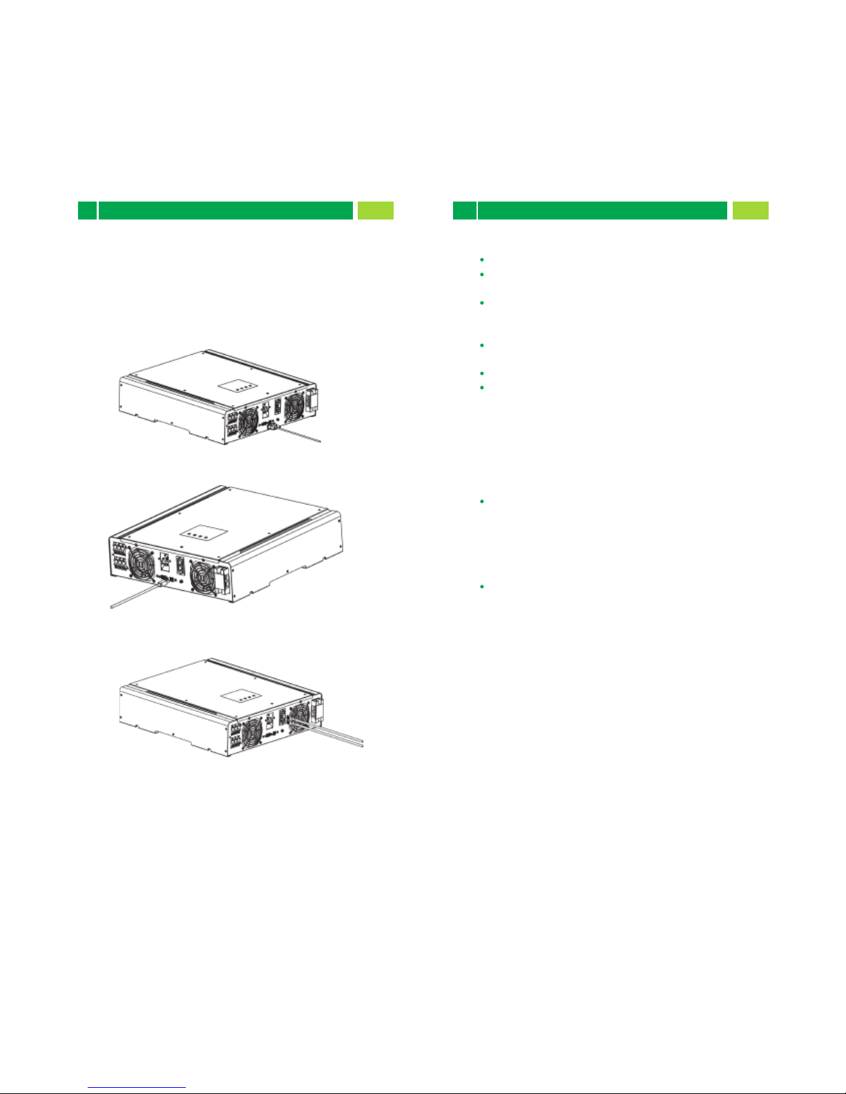
Chart 6 Chart 7 Chart 8
Chart 9
Battery Connection
7
11 12
CAUTION: Before connecng to the baeries, please install a
separate DC circuit breaker between the inverter and the
baeries.
NOTE: Use only sealed, vented or Gel lead acid baeries. Check
the minimum and maximum charging voltage and current when
first using this inverter. If using Lithium iron or Nicd baery,
please consult with the installer for the details.
NOTE: Use a 60VDC/100A circuit breaker.
Follow the steps bellow to implement baery connecon:
Step 1: Check the nominal voltage of baeries. The nominal
input voltage for hybrid inverter is 48VDC.
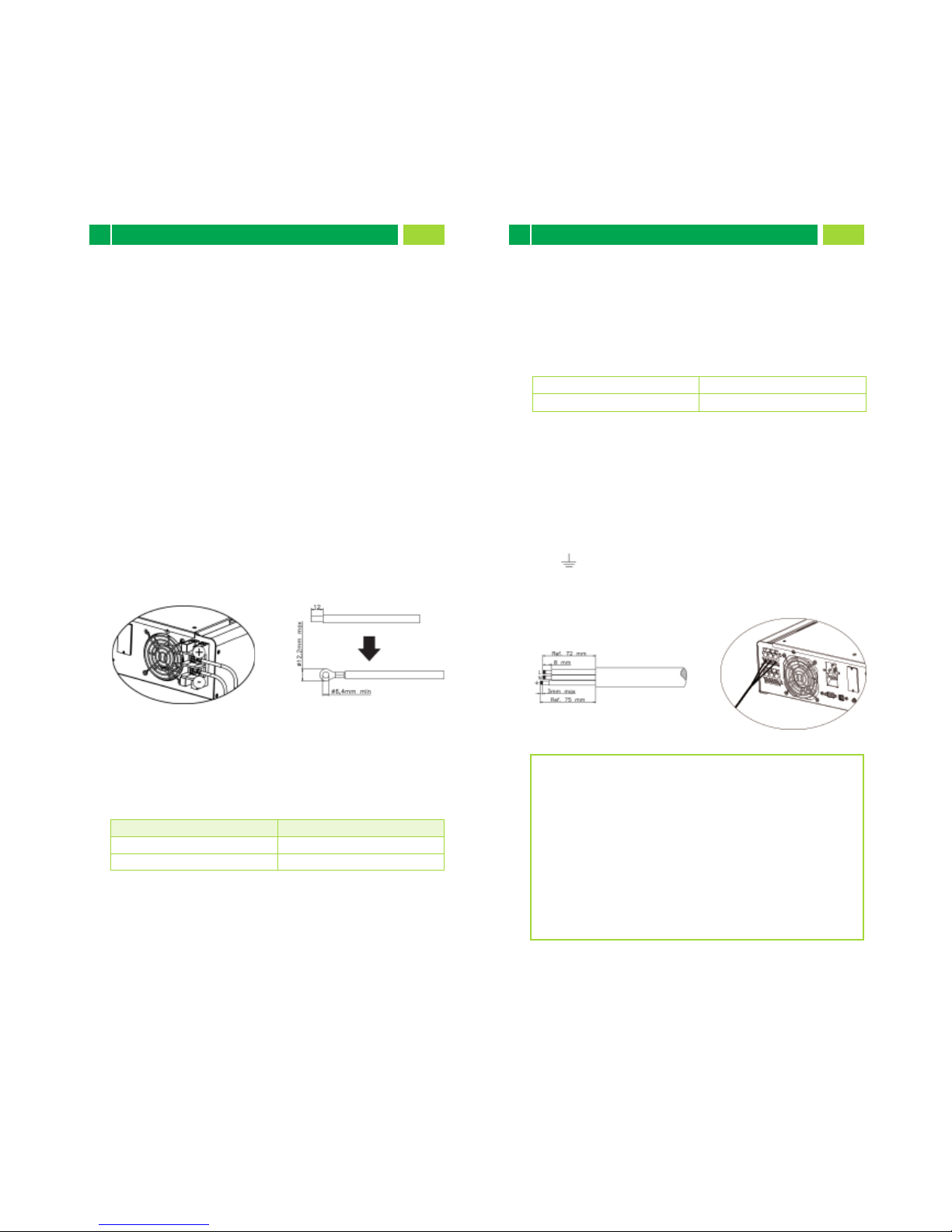
Step 2: Use two baery cables. Remove 12mm from the
insulaon sleeve and insert the bare conductor into cable ring
terminal. Refer to Chart 6.
Step 3: Following baery polarity guide printed near the baery
terminal! Place the external baery cable ring terminal over the
baery terminal. Refer to Chart 7.
RED cable to the posive terminal (+);
BLACK cable to the negave terminal (-).
Step 4: Make sure the wires are securely connected. The
reference ghtening torque is 2.04 N.m.
Load (AC Output) Connection
8
CAUTION: To prevent further supply to the load via the inverter
during any mode of operaon, an addional disconnecon
device should be placed in the building wiring installaon.
WARNING! It's very important for system safety and efficient
operaon to use appropriate cable for AC connecon. To reduce
risk of injury, please use the proper recommended cable size as
below.
Step 1: Remove 8mm from the insulaon sleeve for three
conductors. Shorten phase L and neutral conductor N by 3 mm.
Refer to Chart 8.
Step 2: Connect wires according to polaries indicated on
terminal block. Be sure to connect PE protecve conductor (
Ground symbol to be inserted ) first. Refer to Chart 9.
L→LINE (brown or red)
→Ground (yellow-green)
N→Neutral (blue or black)
Step 3: Make sure the wires are securely connected.
The reference ghtening torque is 0.82 N.m.

The inverter is equipped with RS232 and USB ports and it is
also equipped with a slot for alternave communicaon
interfaces in order to communicate with a PC with
corresponding soware. This intelligent slot is suitable to install
an SNMP card or Modbus card. Follow the procedure below to
connect communicaon wiring and install the soware.
Install monitoring soware on your computer. Detailed
informaon is listed in the next chapter. Aer soware is
installed, you may iniate the monitoring soware and extract
data through the communicaon port.
NOTE: If using the modbus card as your communicaon
interface, install the separately bundled soware. Consult
with your local dealer for more informaon.
Step 1: Check the following requirements before
commissioning:
Ensure the inverter is firmly mounted.
Check if the open circuit DC voltage of PV module meets
requirement (Refer to Secon 6).
Check if the open circuit ulity voltage of the ulity is at
approximately the same as the nominal expected value from
local ulity company.
Check if connecon of AC cable to grid (ulity) is correct if
the ulity is required.
Full connecon to PV modules.
Ensure that the AC circuit breaker (only applied when the
ulity is required), baer circuit breaker and DC circuit
breakers are installed correctly.
Step 2: Switch on the baery circuit breaker and then connect
the PV DC breaker. Aer that, if there is ulity connecon,
switch on the AC circuit breaker. The inverter is now turned on.
There is however no output generaon for loads. Then:
If LCD lights up to display the current inverter status,
commissioning has been successful. Aer pressing “ON”
buon for 1 second when the ulity is detected, the inverter
will start to supply power to the loads. If no ulity exists,
press the “ON” buon for 3 seconds. The inverter will start
to supply power to the loads.
If the red LED lights up, or warning/fault indicator appears
on LCD, an error has occurred. Please inform your installer.
Step 3: Insert CD into your computer and install monitoring
soware in your PC. Follow below steps to install soware.
1. Follow the on-screen instrucons to install the soware.
2. When your computer restarts, the monitoring soware will
appear as shortcut icon located in the system tray.
Communication
9Commissioning
10
For RS232 port, you should use a DB9 cable as follows:
For USB port, you should use a USB cable as follows:
For SNMP or MODBUS card, you should use RJ45 cables as
follows:
13 14

Before inverter operaon, it’s required to set up “Operaon
Mode” via soware. Please strictly follow below steps to set up.
For more details, please check soware manual.
Step 1: Aer turning on the inverter and installing the soware,
please click “Open Monitor” to enter main screen of this
soware.
Step 2: Log in into soware first by entering default password
“administrator”.
Step 3: Select Device Control>>MyPower Management. It is to
set up inverter operaon mode and personalized interface.
Refer to diagram below.
Mode
There are three operaon modes: Grid-e with backup,
Grid-Tie and Off-Grid.
Grid-e with backup: PV power can feed-in back to grid,
provide power to the load and charge baery. There are four
opons available in this mode: Grid-e with backup I, II, III, IV
and V. In this mode, users can configure PV power supply
priority, charging source priority and load supply source
priority. However, when Grid-e with backup IV opon is
selected in PV energy supply priority, the inverter is only
operated between two working logics based on defined peak
me and off-peak me of electricity. Only peak me and
off-peak me of electricity are able to be set up for
opmized electricity usage.
Grid-Tie: PV power only can feed-in back to grid.
Off-Grid: PV power only provides power to the load and
charge baery. No feed-in back to the grid is allowed.
SECTION A:
Standard: It will list local grid standard. It’s requested to have
factory password to make any modificaons. Please check local
dealer only when this standard change is requested.
CAUTION: Incorrect sengs could cause the unit damage or not
working.
SECTION B:
This secon contents may be different based on different
selected types of operaons.
When baery voltage <xx.x V. the AC starts charging: When
selected, once the baery voltage is lower than the seng (xx.x
V), AC will start to charge baery. When this condion is
selected, it’s allowed to enter seng voltage. Otherwise, it’s
impossible to enter any values.
AC charging duraon: This is the me of day that AC (grid) is
allowed to charge baery. When the duraon is set up as
0:00-00:00, there is no me limitaon for AC to charge baery.
AC output ON/Off Timer: Set up on/off me for AC output of
inverter. If seng it as 00:00/00:00, this funcon is disabled.
Nominal Output Voltage: There are 5 opons for high voltage
system to select, 240V, 230V, 220V, 208V and 202V.
Nominal Output Frequency: There are two opons to select,
50HZ or 60HZ.
Initial Setup
11
15 16

Allow to charge baery: This opon is automacally determined
by seng in “Charging source”. It’s not allowed to modify here.
When “NONE” is selected in charging source secon, this opon
becomes unchecked as grey text.
Allow AC to charge baery: This opon is an automacally
determined by seng in ”Charging source” and cannot be
modified here. When “Grid and PV” or “Grid or PV” is selected in
charging source secon, this opon is default selected. Under
Grid-e mode, this opon is invalid.
Allow to feed-in to the Grid: This opon is only valid under
Grid-e and Grid-e with backup modes. Users can decide if this
inverter can feed-in to the grid.
Allow baery to discharge when PV is available: This opon is
automacally determined by seng in “Load supply source (PV
is available)”. When “Baery” is higher priority than “Grid” in
Load supply source (PV is available), this opon is default
selected. Under Grid-e, this opon is invalid.
Allow baery to discharge when PV is unavailable: This opon is
automacally determined by seng in “Load supply source (PV
is unavailable)”. When “Baery” is higher priority than “Grid” in
Load supply source (PV is unavailable), this opon is default
selected. Under Grid-e mode, this opon is invalid.
Allow baery to feed-in to the Grid when PV is available: This
opon is only valid in Grid-e with backup II or Grid-e with
backup III modes.
Allow baery to feed-in to the Grid when PV is unavailable: This
opon is only valid in all opons of Grid-e with backup mode.
PV energy supply priority seng:
1 Baery, 2 Load and 3 Grid.
PV power will charge baery first, then provide power to the
load. If there is any remaining power le, it will feed-in to the
grid.
Baery charging source:
1. PV and Grid (Default)
It is allowed to charge the baery from PV power first. If it’s
not sufficient, grid will charge baery.
2. PV only
Only PV power will be used to charge baery.
3. None
The baery will not be charged by this inverter.
Load supply source:
When PV power is available:
1 PV, 2 Grid, 3 Baery
If baery is not fully charged, PV power will charge baery first.
Remaining PV power will provide power to the load. If it’s not
sufficient, grid will provide power to the load. If grid is not
available at the same me, baery power will back up.
When PV power is not available:
1. 1 Grid, 2 Baery (Default)
Grid will provide power to the load at first. If grid is not
available, baery power will provide power backup.
2. 1 Baery, 2 Grid
Baery power will provide power to the load at first. If
baery power is running out, grid will back up the load.
NOTE: This opon will become ineffecve during AC charging
me and the priority will automacally become 1 Grid and 2
Baery order. Otherwise, it will cause baery damage.
Grid-tie with backup
Grid-e with backup (I) :
st nd rd
st nd
st nd
st nd
st nd
rd
17 18

st nd
PV energy supply priority seng:
1 Load, 2 Baery and 3 Grid.
PV power will provide power to the load first. Then, it will
charge baery. If there is any remaining power le, it will
feed-in to the grid.
Baery charging source:
1. PV and Grid
It’s allowed to charge baery from PV power first. If it’s not
sufficient, grid will charge baery.
2. PV only
It is only allow PV power to charge baery.
3. None
It is not allowed to charge baery no maer it’s PV power or
grid.
Load supply source:
When PV power is available:
1. 1 PV, 2 Baery, 3 Grid
PV power will provide power to the load first. If it’s not
sufficient, baery power will provide power to the load.
When baery power is running out or not available, grid will
back up the load.
2. 1 PV, 2 Grid, 3 Baery
PV power will provide power to the load first. If it’s not
sufficient, grid will provide power to the load. If grid is not
available at the same me, baery power will back up.
When PV power is not available:
1. 1 Grid, 2 Baery: Grid will provide power to the load at
first. If grid is not available, baery power will provide power
backup.
2. 1 Baery, 2 Grid: Baery power will provide power to the
load at first. If baery power is running out, grid will back up the
load
NOTE: This opon will become ineffecve during AC charging
me and the priority will automacally become 1 Grid and 2
Baery order. Otherwise, it will cause baery damage.
Grid-e with backup (II) :
st nd rd
st nd rd
st nd
st nd
st nd
rd
st nd
PV energy supply priority seng:
1 Load, 2 Baery and 3 Grid.
PV power will provide power to the load first. Then, it will
charge baery. If there is any remaining power le, it will
feed-in to the grid.
Baery charging source:
1. PV and Grid
It’s allowed to charge baery from PV power first. If it’s not
sufficient, grid will charge baery.
2. PV only
It is only allow PV power to charge baery.
3. None
It is not allowed to charge baery no maer it’s PV power or
grid.
Load supply source:
When PV power is available:
1. 1 PV, 2 Baery, 3 Grid
PV power will provide power to the load first. If it’s not
sufficient, baery power will provide power to the load.
When baery power is running out or not available, grid will
back up the load.
2. 1 PV, 2 Grid, 3 Baery
PV power will provide power to the load first. If it’s not
sufficient, grid will provide power to the load. If grid is not
available at the same me, baery power will back up.
When PV power is not available:
1. 1 Grid, 2 Baery: Grid will provide power to the load at
first. If grid is not available, baery power will provide power
backup.
2. 1 Baery, 2 Grid: Baery power will provide power to the
load at first. If baery power is running out, grid will back up the
load
NOTE: This opon will become ineffecve during AC charging
me and the priority will automacally become 1 Grid and 2
Baery order. Otherwise, it will cause baery damage.
Grid-e with backup (III):
st nd rd
st nd rd
st nd
st nd
st nd
rd
19 20

Working logic under peak me:
PV energy supply priority: 1 Load, 2 Baery and 3 Grid
PV power will provide power to the load first. If PV power is
sufficient, it will charge baery next. If there is remaining PV
power le, it will feed-in to the grid. Feed-in to the grid is
default disabled.
Baery charging source: PV only
Only aer PV power fully supports the load, the remaining PV
power is allowed to charge baery during peak me.
Load supply source: 1 PV, 2 Baery, 3 Grid
PV power will provide power to the load first. If PV power is not
sufficient, baery power will back up the load. If baery power
is not available, grid will provide the load. When PV power is not
available, baery power will supply the load first. If baery
power is running out, grid will back up the load.
Working logic under off-peak me:
PV energy supply priority: 1 Baery, 2 Load and 3 Grid
PV power will charge baery first. If PV power is sufficient, it will
provide power to the loads. The remaining PV power will feed to
the grid.
NOTE: The max. feed-in grid power seng is available in
parameter seng. Please refer to soware manual.
Baery charging source: PV and grid charge baery
PV power will charge baery first during off-peak me. If it’s not
sufficient, grid will charge baery.
Load supply source: 1 PV, 2 Grid, 3 Baery
When baery is fully charged, remaining PV power will provide
power to the load first. If PV power is not sufficient, grid will
back up the load. If grid power is not available, baery power
will provide power to the load.
Grid-e with backup (IV):
Users are only allowed to set up peak me and off-peak
electricity demand.
st nd rd
st nd rd
st nd rd
rdst nd
PV energy supply priority seng:
1 Load, 2 Baery and 3 Grid
PV power will provide power to the load first. If PV power is
sufficient, it will charge baery next. If there is remaining PV
power le, it will feed-in to the grid.
Baery charging source:
1. PV and Grid: It’s allowed to charge baery from PV power
first. If it’s not sufficient, grid will charge baery.
2. PV only: It is only allow PV power to charge baery.
3. None: It is not allowed to charge baery no maer it’s PV
power or grid.
Load supply source:
When PV power is available:
1. 1 PV, 2 Baery, 3 Grid
PV power will provide power to the load first. If it’s not
sufficient, baery power will provide power to the load.
When baery power is running out or not available, grid will
back up the load.
2. 1 PV, 2 Grid, 3 Baery
PV power will provide power to the load first. If it’s not
sufficient, grid will provide power to the load. If grid is not
available at the same me, baery power will back up.
When PV power is not available:
1. 1 Grid, 2 Baery: Grid will provide power to the load at
first. If grid is not available, baery power will provide power
backup.
2. 1 Baery, 2 Grid: Baery power will provide power to
the load at first. If baery power is running out, grid will back
up the load
NOTE: This opon will become ineffecve during AC charging
me and the priority will automacally become 1 Grid and 2
Baery order. Otherwise, it will cause baery damage.
Grid-e with backup (V): Under this mode, inverter will
automacally disconnect from grid to allow baery to support
loads when baery can not discharge due to high grid voltage.
st nd rd
st nd rd
st nd rd
st nd
st nd
st nd
21 22

PV energy supply priority seng: 1 Load, 2 Baery
PV power will provide power to the load first and then charge
baery. Feed-in to the grid is not allowed under this mode. At
the same me, the grid relay is connected in Inverter mode.
That means the transfer me from inverter mode to baery
mode will be less than 15ms. Besides, it will avoid overload fault
because grid can supply load when connected load is over 3KW.
Baery charging source:
1. PV or Grid: If there is remaining PV power aer supporng
the loads, it will charge baery first. Only unl PV power is
not available, grid will charge baery. (Default)
2. PV only: It is only allow PV power to charge baery.
3. None: It is not allowed to charge baery no maer it’s PV
power or grid.
st nd
Load supply source:
When PV power is available:
1. 1 PV, 2 Baery, 3 Grid (Default)
PV power will provide power to the load first. If it’s not
sufficient, baery power will provide power to the load. When
baery power is running out or not available, grid will back up
the load.
2. 1 PV, 2 Grid, 3 Baery
PV power will provide power to the load first. If it’s not
sufficient, grid will provide power to the load. If grid is not
available at the same me, baery power will back up.
When PV power is not available:
1. 1 Grid, 2 Baery
Grid will provide power to the load at first. If grid is not
available, baery power will provide power backup.
2. 1 Baery, 2 Grid (Default)
Baery power will provide power to the load at first. If baery
power is running out, grid will back up the load.
NOTE: This opon will become ineffecve during AC charging
me and the priority will automacally become 1 Grid and 2
Baery order. Otherwise, it will cause baery damage.
st nd rd
st nd
st nd
st nd
st nd
rd
Grid-Tie
Under this operaon mode, PV power only feeds-in to the
grid. No priority seng is available.
Off-Grid
Off-Grid (I): Default seng for off-grid mode.
PV energy supply priority seng: 1 Baery, 2 Load
PV power will charge baery first. Aer baery is fully charged,
if there is remaining PV power le, it will provide power to the
load. Feed-in to the grid is not allowed under this mode. At the
same me, the grid relay is connected in Inverter mode. That
means the transfer me from inverter mode to baery mode
will be less than 15ms. Besides, it will avoid overload fault
because grid can supply load when connected load is over 3KW.
st nd
Off-Grid (II)
23 24

PV energy supply priority seng: 1 Load, 2 Baery
PV power will provide power to the load first and then charge
baery. Feed-in to the grid is not allowed under this mode. The
grid relay is NOT connected in Inverter mode. That means the
transfer me from inverter mode to baery mode will be less
than 15ms.
st nd
Off-Grid (III)
Baery charging source:
1. PV or Grid: If there is remaining PV power aer supporng
the loads, it will charge baery first. Only unl PV power is
not available, grid will charge baery.
2. PV only: It is only allow PV power to charge baery.
3. None: It is not allowed to charge baery no maer it’s PV
power or grid.
NOTE: It’s allowed to set up AC charging duraon.
Load supply source:
When PV power is available: 1 PV, 2 Grid, 3 Baery
PV power will provide power to the load first. If it’s not
sufficient, grid will provide power to the load. If grid is not
available at the same me, baery power will back up.
When PV power is not available:
1. 1 Grid, 2 Baery: Grid will provide power to the load at
first. If grid is not available, baery power will provide power
backup.
2. 1 Baery, 2 Grid: Baery power will provide power to
the load at first. If baery power is running out, grid will back
up the load.
NOTE: This opon will become ineffecve during AC charging
me and the priority will automacally become 1 Grid and 2
Baery order. Otherwise, it will cause baery damage.
st nd
st nd
st nd
st nd
rd
Baery charging source:
1. PV or Grid: If there is remaining PV power aer supporng
the loads, it will charge baery first. Only unl PV power is
not available, grid will charge baery.
2. PV only: It is only allow PV power to charge baery.
3. None: It is not allowed to charge baery no maer it’s PV
power or grid.
NOTE: It’s allowed to set up AC charging duraon.
Load supply source:
When PV power is available: 1 PV, 2 Baery, 3 Grid
PV power will provide power to the load first. If it’s not
sufficient, baery power will back up the load. Only aer baery
power is running out and stop providing the load, Grid will back
up the load. At this me, baery power is in low level and PV
power only can charge baery when “Allow to charge baery” is
enabled. Only when baery voltage is back to re-discharging
point, PV power will provide power to the load again.
When PV power is not available:
1. 1 Grid, 2 Baery: Grid will provide power to the load at
first. If grid is not available, baery power will provide power
backup.
2. 1 Baery, 2 Grid: Baery power will provide power to the
load at first. If baery power is running out, grid will back up the
load.
NOTE: This opon will become ineffecve during AC charging
me and the priority will automacally become 1 Grid and 2
Baery order. Otherwise, it will cause baery damage.
st nd
st nd
st nd
st nd
rd
25 26

NOTE: If backlight shuts off, you may acvate it by pressing any
buon. When an error occurs, the buzzer will connuously
sound. You may press any buon to mute it.
Display
Buon Operaon Funcon
Funcon
Indicates AC input voltage or frequency.
Vac: voltage, Hz: frequency
ENTER/ON
Short press.
Short press. Return to previous menu.
Short press.
Short press.
Enter query menu.
Press and hold the
buon for approximately
1 second when the ulity
is detected or 3 seconds
without the ulity.
Press and hold the
buon unl the buzzer
connuously sounds.
This inverter is able to provide
power to connected loads via AC
output connector.
If it’s in query menu, press this
buon to jump to next selecon
or decrease value.
Mute alarm in standby mode or
baery mode.
Turn off power to the loads.
If it’s in query menu, press this
buon to confirm selecon or
entry.
ESC/OFF
Down
UP
Indicates solar panels.
Icon flashing indicates PV input voltage or is out of
range.
Indicates ulity.
Icon flashing indicates ulity voltage or frequency
is out of range.
Indicates baery condion. And the lace of the
icon indicates baery capacity.
Indicates AC output for loads is enabled and
inverter is providing power to the connected
loads.
Indicates AC output for loads is enabled but there
is no power provided from inverter. At this me,
no baery and the ulity are available. Only PV
power exists but is not able to provide power to
the connected loads.
Indicates PV input voltage or power.
Volt: voltage, KW: power
Indicates baery voltage or percentage.
Volt: voltage, %: percentage
Indicates charging current to baery.
Indicates that the warning occurs.
Indicates that the fault occurs.
Indicates fault code or warning code.
Indicates date and me, or the date and me
users set for querying energy generaon.
Indicates AC output power, voltage, frequency, or
load percentage.
KW: power, Vac: Voltage, Hz: frequency, %: Load
percentage
NOTICE: To accurately monitor and calculate the energy
generaon, please calibrate the mer of this unit via soware
every one month. For the detailed calibraon, please check the
user manual of bundled soware.
Real-me operaon status
Secon 12-5 describes all
operaon condions when the
inverter is set up at “Grid-e
with backup (I)” mode.
Operation
12
This display is operated by
four buons.
12.1 Interface
12.3 Button Definition
12.2 LCD Information Define
Icon
Icon
flashing indicates baery is not connected.
Indicates overload.
Indicates PV energy generated.
flashing indicates the baery voltage is too low.
27 28

Setting Display Procedure
Input voltage or frequency of AC input
Frequency, voltage, power or load percentage of AC output
Input voltage or power of PV input.
Baery voltage or capability percentage.
Date and me.
Today or total energy generated.
Mode of query energy generated.
Procedure
The display shows current contents that have been set. The
displayed contents can be changed in query menu via buon
operaon. Press ‘Enter’ buon to enter query menu. There are
seven query selecons:
12.4 Query Menu Operation
Procedure
Frequency, voltage, power or percentage of AC output
Procedure
Input voltage or power of PV input.
Procedure
Baery voltage or percentage.
Procedure
Date and me.
29 30

Procedure
Today or total energy generated.
Procedure
Mode of query energy generated.
Energy generaon display of selected day
LCD Display:
Energy generaon display of selected month
Procedure
LCD Display:
Inverter mode with grid connected
LCD Display:
LCD Display Descripon
Energy generaon display of selected year
Procedure
12.5 Query Menu Operation
Below is only contained LCD display for grid-e with backup
mode (I). If you need to know other operaon mode with LCD
display, please check with installer.
This inverter is connected to grid and working with DC/INV
operaon.
PV power is sufficient to charge
baery, provide power to loads,
and then feed in to the grid.
PV power is sufficient to charge
the baery first. However,
remaining PV power is not
sufficient to back up the load.
Therefore, remaining PV power
and the ulity are supplying
power to the connected load.
PV power is generated, but not
sufficient enough to charge
baery by itself. PV power and
the ulity are charging baery at
the same me. And the ulity is
also supplying power to the
connected load.
31 32

LCD Display Descripon
Inverter mode without grid connected
This inverter is working with DC/INV operaon and not
connecng to the grid.
PV power is sufficient to charge
baery and provide power to the
connected loads. At the same
me, the ulity is out of range.
icon is flahsing.
PV power is generated, but not
sufficient enough to power loads
by itself. PV power and baery
are providing power to the
connected loads at the same
me. At the same me, the
ulity is out of range. icon
is flahsing.
PV power is not detected or
available at this moment. Only
baery power is available to
provide power to connected
loads. At the same me, the
ulity is out of range. and
icons are flahsing.
Only PV power is available to
provide power to connected
loads. At the same me, the
ulity is out of range. No baery
is connected or baery is not
available to use at this moment.
and icons are
flahsing.
This inverter is disabled to
generate power to the loads via
AC output. PV power is sufficient
to charge baery first.
Remaining PV power will feed in
back to grid.
This inverter is disabled to
generate power to the loads via
AC output. PV power and ulity
are charging baery at the same
me because of insufficient PV
power.
This inverter is disabled to
generate power to the loads via
AC output. PV power is feeding
power back to the ulity. No
baery is connected or baery is
not available to use at this
moment. icon is flashing.
PV power is sufficient to provide
power to loads and feed power
back to ulity.No baery is
connected or baery is not
available to use at this moment.
icon is flashing.
PV power and ulity are
providing power to the
connected loads because of
insufficient PV power. No baery
is connected or baery is not
available to use at this moment.
icon is flashing.
33 34

Charging Management
13
LCD Display Descripon
Bypass mode
The inverter is working without DC/INV operaon and
connecng to the loads.
PV power is not detected or
available. Only ulity is charging
baery and providing power to
connected loads. icon is
flashing.
PV power and baery are not
detected or available to use at
this moment. Only ulity is
available to provide power to
connected loads. and
icons are flashing.
LCD Display
Baery type
Sealed lead acid
baery
AGM/Gel baery
Bulk Charging Voltage
56 53.6 V
56.4 54.0 V
Recommended floang
charging voltage
Descripon
Standby mode :
The inverter is working without DC/INV operaon and load
connected.
This inverter can connect to baery types of Sealed lead acid
baery, Vented baery and Gel baery. Below is recommended
bulk charging voltage and floang charging voltage table based
on different baery types.
The ulity is out of range. This
inverter is disabled on AC output
or even AC power output is
enabled, but an error occurs on
AC output. Only PV power is
sufficient to charge baery.
icon is flashing.
This inverter is disabled to
generate power to the loads via
AC output. PV power is not
detected or available at this
moment. Only ulity is available
to charge baery. icon is
flashing.
This inverter is disabled to
generate power to the loads via
AC output connector. PV power
and the ulity are not detected
or available at this moment.
Three icons are flashing.
Charging voltage Default
Value
25A
54.0 Vdc
56.0 Vdc
60.0 Vdc
Max. charging current
Baery overcharge protecon
Max. absorpon charging
voltage(default)
Floang charging voltage
(default)
Note
This can be adjusted via
soware from 5Amp to
25Amp.
It can be adjusted via
soware from 50Vac to
58Vdc.
It can be adjusted via
soware from 50Vac to
58Vdc.
This value is 2 Vdc higher
than max. charging voltage.
Charging process based on
default seng.
3 stages:
First – max. charging voltage
increases to 56V;
Second- charging voltage will
maintain at 56V unl charging
current is down to 5 Amp;
Third- go to floang charging
at 54V.
35 36
Table of contents
Other Replus Inverter manuals
Popular Inverter manuals by other brands

Lumiax
Lumiax Epoch Series user manual

AE Conversion
AE Conversion PS350 Installation and operation manual

AIMS Power
AIMS Power PWRINV5K24012W instruction manual

Goodwe
Goodwe GW-GW5000-EH user manual

Vanner
Vanner VLT12-600 owner's manual

Generac Power Systems
Generac Power Systems PWRcell XVT076A03 Installation and owner's manual