HD-4002DM User Guide and Install Manual Page 4
System Installer must adhere to Article 820-40 of the NEC that provides guidelines for proper grounding and species
that the cable ground shall be connected to the grounding system of the building, as close to the point of cable entry
as possible.
UNPACKING AND INSPECTION
Eachunitisshippedfactorytested.Ensureallitemsareremovedfromthecontainerpriortodiscardinganypackingmaterial.
Thoroughlyinspecttheunitforshippingdamagewithparticularattentiontoconnectorsandcontrols.Ifthereisanysignofdamage
totheunitordamagedorlooseconnectorscontactyourdistributorimmediately.Donotputtheequipmentintoserviceifthereis
anyindicationofdefectordamage.
Itishighlyrecommendedthatqualitycablesandconnectorsbeusedforallvideoandaudiosourceconnections.
1. TheunitisdesignedtoberackmountedinastandardEIA19”rack.
2. TheunitcomesstandardwithHDMI,Component,andCompositevideoinputs.TheHDTencoder/modulatorareintelligently
designedtodetectthevideoinputfromthevideosource.HDMI Connection: Connect the HDMI cable(s) from the video
source(s)intotheHDMIinput(s).IfusingaComponent Video Cable, connect the Y (Green), Pb (Blue), and Pr (Red) video
sourcecabletotheunit’sComponentinputports.IfusingaComposite Videosource,usea75ΩcoaxialcablewithRCA
connectors to connect the video source(e.g.,CATV,DVD,VCR,Camera)totheunit’sCVBSport(IN1…IN2,IN3,IN4
dependingonyourmodel).
3. Repeatthisstepforeachvideosourceconnection.
4. Component / Composite Audio inputs: Connect A/V audio input (Left / Right Audio) use RCA cables to connect the audio
source to the red / white AUDIO L and AUDIO R INPUT jacks(IN1…IN2,IN3,IN4dependingonyourmodel).Repeatthisstep
foreachaudiosourceconnection.
5. Besurethevideoandaudioconnectionsforeachsourceareconsistentwiththeunit’sinputs(IN1…IN2,IN3,IN4dependingon
yourmodel).
6. Useaquality75Ωcoaxialcablewith“F”connectorsfromtheunit’sRF OUT jack to the distribution system (combiner or
reversesplitter)ordirectlytoatelevision.
7. IfyourdeviceisequippedwithanIPoutput-connecttheEthernetcabletotheIPoutputRJ45connector.
8. Connect the included power cord to the unit’s POWERplug.
9. ConnectthepowercordtoanappropriatelyratedACpoweroutlet.
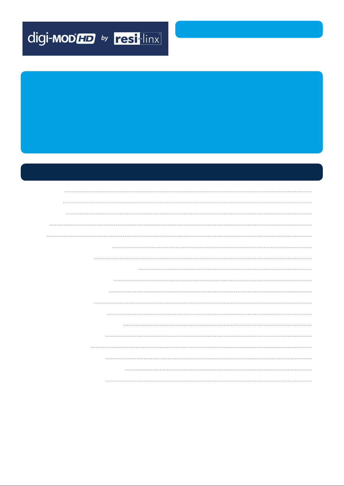
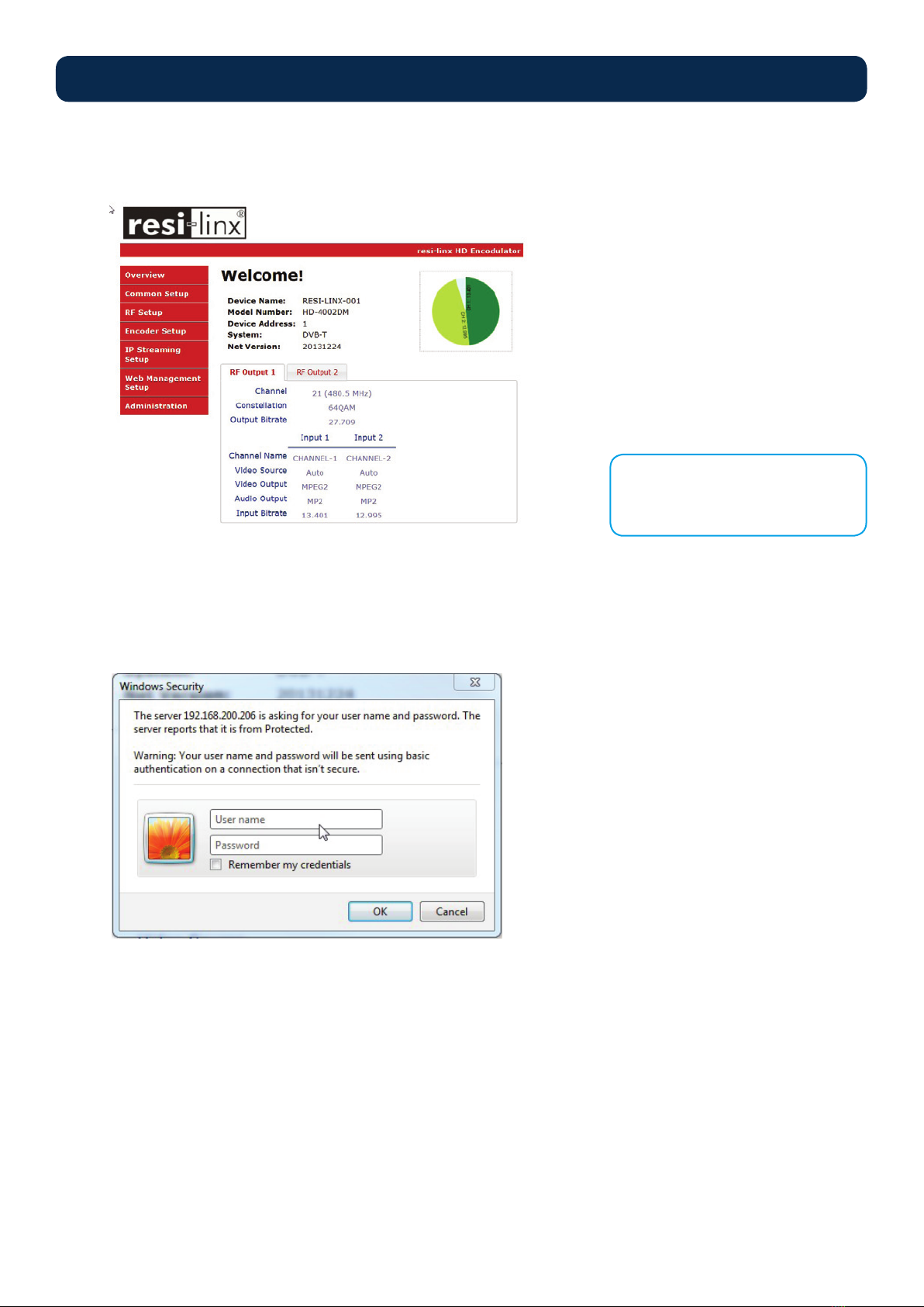
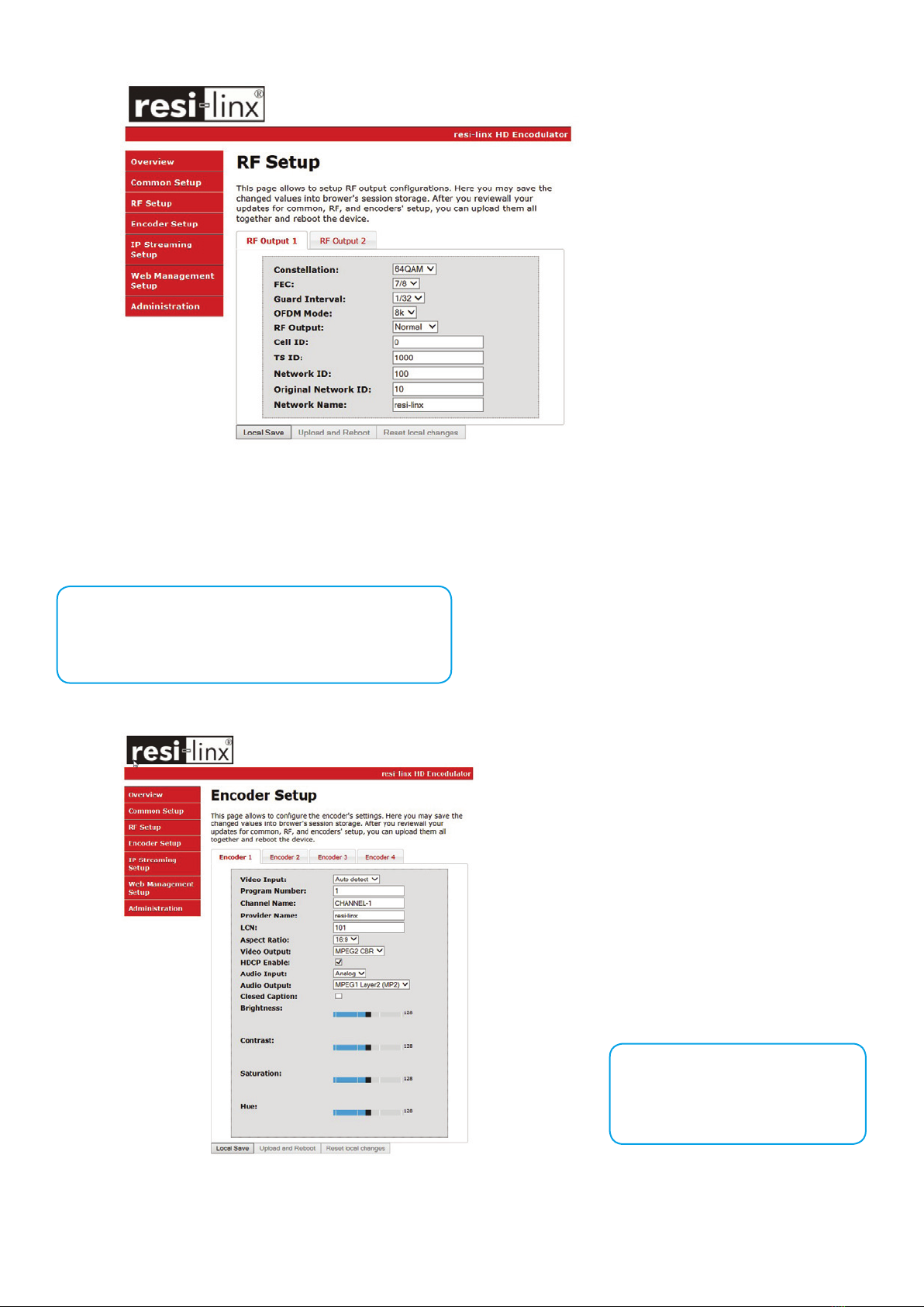
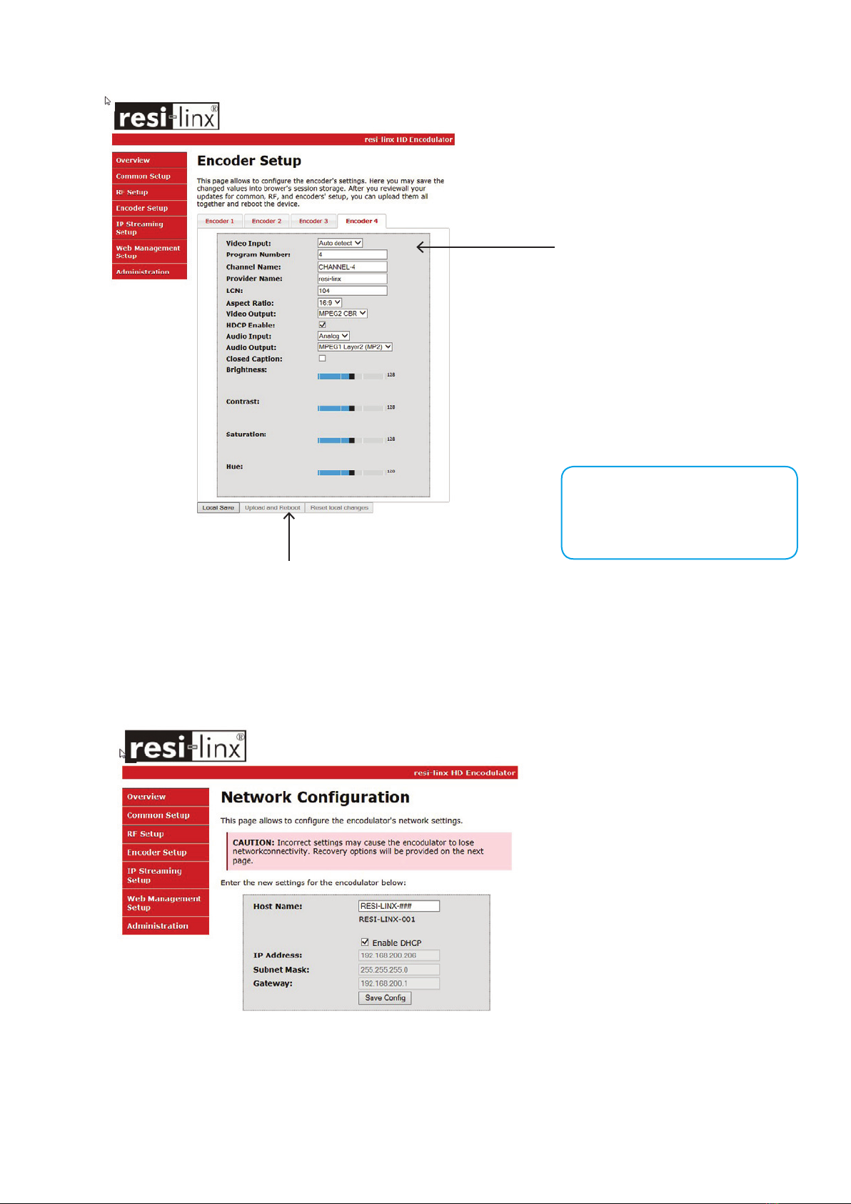
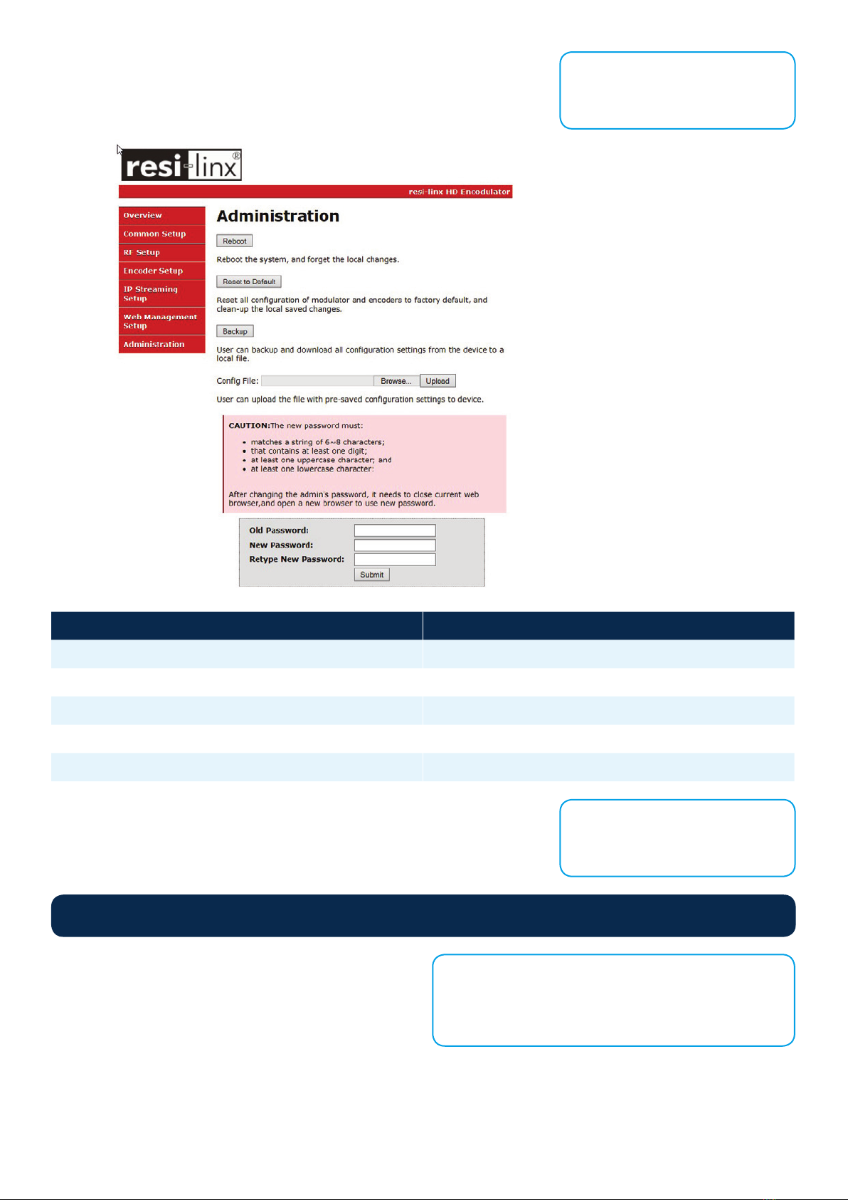
TosetupandprogramtheEncoderyoucanusetheGUIinterfaceortheLCDFrontPanel.
1. Connect an Ethernet cable directly (no Cross Over cable required) to the Web Management Port on the rear panel of the
encoderorconnecttheEthernetcabletoanEthernetswitch.ConnectanEthernetCabletoyourPC.
2. Using a Windows-based PC Select Windows Icon
3. Go to My Computer
4. Select Network
5. Allow UPnP to locate and list the device(s) in the right panel
6. RightClickandSelect“ViewdeviceWebpage”.
Installation
Hardware Installations and Connections
DEVICE Programming and Setup
Connecting to the GUI Interface
NOTE:
For Setup Using Front Panel LCD:
Go to page 11 in this manual.