3. GENERAL INSTALLATION STEPS AND
MAINTAINANCE
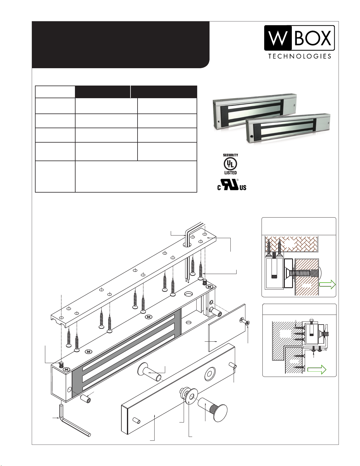
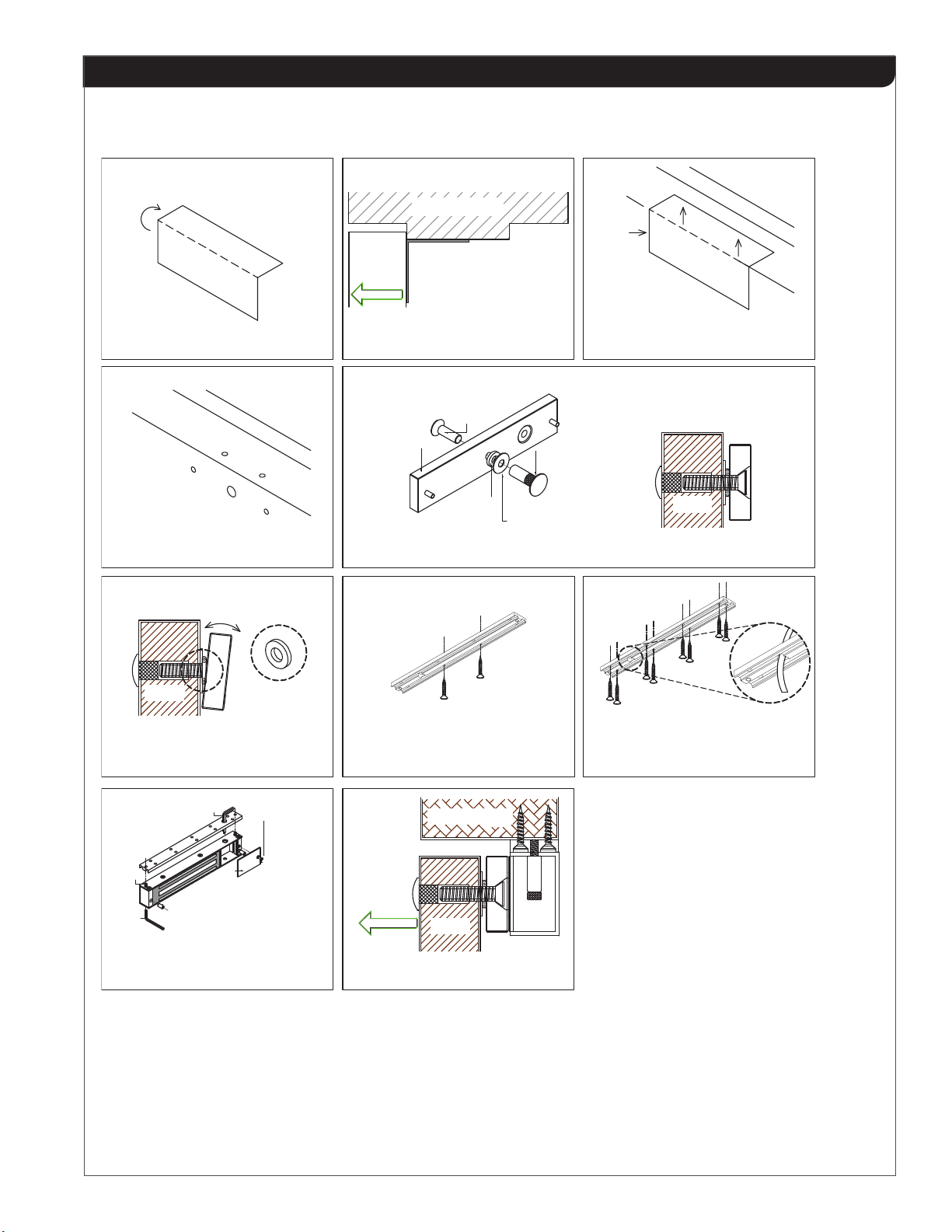
1. Drill the armature plate holes in the door using the sticker
template provided.
2. Attach the armature plate to the door with the hardware
provided as per Figure 5 on page 3.
3. With the door closed, mark the door frame at the edge of
the armature, in order to properly align the electromagnet
to the armature.
4. Attach the mounting plate to the door frame using the
self-tapping screws provided.
Align the mounting plate with the mark from Step 3.
5. Insert the wires through the hole in the mounting plate
and into the electromagnet. Attach the electromagnet
to the mounting plate with the Allen head xing screw.
6. Screw in the anti-tamper nuts to prevent unauthorized
access and make sure to fully tighten the xing screw with
an Allen Key.
7. Connect the power wires in accordance with NFPA 101.
8. Typical wiring method shall be in accordance with CSA
C22.1, Canadian Electrical Code, Part I, Safety Standard
for Electrical Installations, Section 32.
9. It is recommended to apply a light coating of silicon
lubricant to the mating surfaces on a monthly basis to
inhibit rust.
Notes:
Install in an Indoor Dry Location.
Use Caution when Changing Factory Default Setting.
4. TROUBLE SHOOTING
1. Door not locked:
- Incorrect wiring or no power from power supply
2. Reduced holding force:
- Poor contact of electromagnet and armature.
- Be sure armature is loose enough so that it can fully
contact electromagnet along it is the entire length
- Mating surfaces are dirty or damaged.
- Improper input voltage or wire size.
IMPORTANT!
12 / 24 VDC
Power Output
12 VDC
Setting
24 VDC
Setting
12 / 24 VDC
Power Input
+
-
Set the jumper position according
to the power input before
switching ON the power.
600Lb. / 1200Lb. Magnetic Locks Installation Instructions
Page 2 of 4