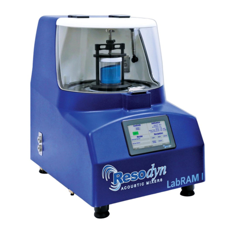
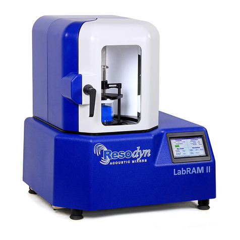
Resodyn LabRAM II User manual

LabRAM II Spray System Instruction Manual
Rev. 042618
Resodyn Acoustic Mixers, Inc. 2 www.resodynmixers.com
Purchase and Installation Information

LabRAM II Spray System Instruction Manual
Rev. 042618
Resodyn Acoustic Mixers, Inc. 3 www.resodynmixers.com
Table of Contents
1Introduction .....................................................................................................................................4
2Definitions........................................................................................................................................5
3Safety Information...........................................................................................................................6
3.1 General Safety and Assembly Considerations........................................................6
3.2 Warnings and Cautions...........................................................................................7
3.3 Important Safety Notes...........................................................................................8
4General Notes................................................................................................................................11
4.1 System Description...............................................................................................11
4.2 Voltage Level and Power Consumption ................................................................13
5Installation .....................................................................................................................................14
5.1 Spray System Overall Assembly Pictures.............................................................14
5.2 Spray System Installation......................................................................................16
5.3 Installing the Ultrasonic Atomizer Nozzle Generator .............................................19
5.4 Connect Peristaltic Pump Options to Ultrasonic Nozzle ........................................19
5.5 Connecting Syringe Pump to Ultrasonic Nozzle....................................................20
6Operating Instructions..................................................................................................................21
6.1 Power-up Equipment ............................................................................................21
6.2 LabRAM II Spray System Operation .....................................................................22
6.3 Power-Down.........................................................................................................28
6.4 Maintenance and Cleaning ...................................................................................29
6.5 General Cleaning Instructions...............................................................................32
7Warranty and Service ...................................................................................................................33
7.1 Limited Warranty...................................................................................................33
7.2 Maintenance and Service......................................................................................33
8Supplemental Information............................................................................................................34
8.1 Other Operating Manuals......................................................................................34
8.2 Replacement Parts ...............................................................................................35

LabRAM II Spray System Instruction Manual
INTRODUCTION
Resodyn Acoustic Mixers, Inc. 4 Rev. 030118
1 Introduction
The LabRAM II Spray System integrates liquid metering components with an innovative,
low-frequency, acoustic mixer, the LabRAM II. The patented, enabling technology,
ResonantAcoustic®Mixing (RAM), is a groundbreaking approach to multiple mixing
applications.
RAM is distinctly different from conventional mixing methods such as impeller agitation
and diffusion blending. Conventional methods work by producing bulk fluid flow in a
mixture with restricted mixing zones. RAM mixing is based on using acoustic energy to
mix liquids, slurries, and powders rapidly, efficiently, and thoroughly. Please refer to the
Users’ Manual provided with your LabRAM II or LabRAM II mixer for more detailed
information about ResonantAcoustic®mixing or visit www.resodynmixers.com.
This manual will provide vital information to properly perform the following:
•Safely operate your LabRAM II Spray System
•Understand the major components of your LabRAM II Spray System
•Understand power requirements
•Set up the LabRAM II Spray System equipment
•Operate the LabRAM II Spray System equipment
•Clean and maintain the equipment
•Schedule equipment service and perform scheduled maintenance
•Obtain additional accessories or replacement parts
The LabRAM II Spray System is supplied with a fixture to hold either a 16 fl oz (0.47 liters)
or a 32 fl oz (0.95 liters) mixing vessel that is 3.5” (8.9 cm) in diameter and 4” or 8” in
height (10.2 cm). The system is equipped with an interlock safety switch to ensure that the
LabRAM II’s acrylic cover is in the correct position before and during operation.
The LabRAM II Spray System is designed for use in non-hazardous environments.
Not covered in this manual are:
•Use of RAMWare or RAMware2
•Repair of the LabRAM II mixer

LabRAM II Spray System Instruction Manual
DEFINITIONS
Resodyn Acoustic Mixers, Inc. 5 Rev. 030118
2 Definitions
Acceleration: A change in velocity with respect to time that is expressed in “g.”
Different mix media mixes at different accelerations, based on the
material and the expected results,
ATEX: European Union (EU) directives describing what equipment and work
environment is allowed in an area with an explosive atmosphere.
LabRAM II Spray System is designed for non-hazardous environments.
Damping: A term to quantify the instantaneous amount of energy absorbed by the
mix media while mixing.
g: A measure of acceleration expressed as a multiple of the gravitational
acceleration applied to the vessel and mix media during mixing. For
example, 10 g is 10 times the force of gravity. It may also be shown as
g or g’s. Another term that may be used to describe the acceleration is
“gravities.”
HMI: Human Machine Interface control and input system screen used to
operate the LabRAM II.
Headspace: The volume of compressible air, gas, or void space above the fluid in
the vessel that is not occupied by the Mix Media.
Mixing Media: Defined as the material inside the mixing vessel.
Mixing Power: The amount of power being delivered by the RAM system to perform
mixing.
Mixing Regime: This term identifies certain modes of mixing. For example, a fluid will
change regimes as it undergoes changes in acceleration, from an
incompressible liquid containing few headspace bubbles, to a fluid that
is fully integrated with the compressible headspace such that the two
are indistinguishable from each other.
RAM: ResonantAcoustic®Mixing or ResonantAcoustic® Mixer.
RAMWare2: Control software that runs on a Personal Computer (PC) and provides
control to, and feedback from, the mixing process
Resonance: The frequency (nominally 60 Hz) at which the system operates in the
most efficient manner.
Vacuum: Internal vessel pressure that is less than atmospheric pressure.

LabRAM II Spray System Instruction Manual
SAFETY
Resodyn Acoustic Mixers, Inc. 6 Rev. 030118
3 Safety Information
Every effort has been made to assure that the LabRAM II Spray System is easy to use,
reliable, and safe. This section outlines the general safety considerations and highlights
important information with caution and warning symbols used throughout this document.
3.1 General Safety and Assembly Considerations
For safe operation, the LabRAM II Spray System should be operated only within the limits
outlined in the system specifications. Specifically, the following classification defines
acceptable use and conditions for the LabRAM II Spray System:
•Indoor use only.
•Main supply voltage fluctuations are not to exceed ±10% of the nominal supply
voltage.
•Suitable for intermittent or continuous operation.
•For use in non-hazardous environments as classified by the United States National
Electrical Code (NEC) Class and Division and ATmospheres EXplosibles (ATEX)
directive for European Union countries.
For thorough and critical installation information, make sure to access, download,
and carefully review the documents provided by the component manufactures of
the LabRAM II Spray System.
For safe operation of the Spray System Components, carefully observe and follow
these component instructions:
Ultrasonic Atomizer Nozzle Generator
1
:
Read the instructions in the Ultrasonic Atomizer Nozzle Generator Operating Manual.
KDS Legato 100 Series syringe pump
2
:
Read the instructions in the KDS Legato 100 Series User’s Manual.
Masterflex L/S 07528-20 Precision Variable Speed Console Drive
3
:
Read the instructions in the Masterflex L/S Operating Manual.
Masterflex L/S PTFE Tubing Pump, Model 77390-00
4
:
Read the instructions in the Masterflex L/S PTFE Tubing Pump, Model 77390-00
Operating Manual.
1
See the Ultrasonic Atomizer Nozzle Generator information available at
http://www..com/Ultrasonic_Generator.html
2
See the KDS Legato 100 Series User’s Manual available at
http://www.kdscientific.com/downloads/KDS%20Literature/Manuals/Legato%20100%20Manual%20Rev%2
0D%20.pdf
3
See the Masterflex L/S Operating Manual available at
http://www.coleparmer.com/Assets/manual_pdfs/07528-10,%20-20,%20-30%20ENGLISH.pdf
4
See the Masterflex L/S PTFE Tubing Pump Operating Manual available at
http://www.coleparmer.com/Assets/manual_pdfs/77390-00.pdf

LabRAM II Spray System Instruction Manual
SAFETY
Resodyn Acoustic Mixers, Inc. 7 Pub 042618
3.2 Warnings and Cautions
Throughout the manual, the following symbols are used to identify warnings and cautions:
The caution symbol indicates a potential hazardous situation which
could result in minor injury or damage to the product.
The high voltage symbol indicates the possibility of electrical
shock.
This symbol means turn off the electrical supply before removing
any cover with the symbol attached. Failure to do so may cause
exposure to electrical shock hazard.
Access to electrical components should only be carried out by a
licensed electrician or qualified electrical engineer.
NEVER attempt to modify any electrical components or circuits as
this may affect the safe operation of the machine.
Electrostatic Discharge (ESD) sensitive components.

LabRAM II Spray System Instruction Manual
SAFETY
Resodyn Acoustic Mixers, Inc. 8 Rev. 030118
3.3 Important Safety Notes
This equipment should only be operated by trained and qualified
personnel with access to and knowledge of the equipment
functions..
Mixing operations can generate heat and internal pressure depending on material and
mixer accelerations. Always pre-test materials and processes. Do not mix materials longer
than what has been characterized as safe.
Do not disable or tamper with any safety items, such as safety interlock switches located
on the LabRAM II Spray System.
Note: Changes in noise level or frequency are common during mixing operations. If
rattling, metal-on-metal, or obnoxious noises occur, turn off the LabRAM II Spray
System and call or email the Resodyn Acoustic Mixers Technical Support line at
406-497-5333.
WARNINGS: Tubing breakage may result in fluid being sprayed
from pump. Use appropriate measures to protect operator and
equipment.
Turn Peristaltic Pump System off before removing or installing
tubing. Avoid fingers or loose clothing getting caught in drive
mechanism.
CAUTIONS: When changing flow direction, allow the peristaltic
pump to come to a complete stop before starting again. Failure to
do so could cause permanent damage to the motor.
Replace the fuse only with one of the same type and rating. The
fuse rating and type are stated on the rear panel.
Use only pre-formed Masterflex L/S PTFE tubing. Use of other
tubing may result in premature or unknown failure modes.
Use recommended fittings only. Use of improper fittings and/or
improper connection to fittings may result in leakage at the
fittings.
A pressure relief/bypass valve must always be installed in a
potentially high-pressure system to prevent the pump from
exceeding the maximum rated pressure; i.e., 100 psig (6.8 bar)
for the peristaltic pump system.

LabRAM II Spray System Instruction Manual
SAFETY
Resodyn Acoustic Mixers, Inc. 9 Pub 042618
DANGER: Disconnect all power from the pump before any
cleaning operation is started.
WARNING: Disconnect all power from the pump before attempting
any maintenance.
CAUTION: To avoid electrical shock, the pump power cord
protective grounding conductor must be connected to ground. Not
for operation in wet locations as defined by EN61010-1.
If the pump product is not used in a manner specified in the
instructions, the protection provided by the equipment may be
impaired.
3.3.1.1 Ultrasonic Nozzle
Avoid contact with the energized nozzle tip. This device will cut through tissue and
damage cells when energized.
Ultrasonic Atomizer Nozzle Generator
3.3.2.1 Before operating the ultrasonic atomizer, check for any damage that may
be related to shipping.
3.3.2.2 Ensure that a properly grounded110/120 VAC outlet is available.
3.3.2.3 Do not plug this unit into a 220/240 VAC outlet.
3.3.2.4 Alterations to unit without appropriate authorization will void warranty.
3.3.2.5 Disassembly of atomizer (i.e., generator) will void warranty.
Figure 3-1: Ultrasonic Nozzle Shown in cut-away
view of Spray System
Nozzle
Tip

LabRAM II Spray System Instruction Manual
SAFETY
Resodyn Acoustic Mixers, Inc. 10 Pub 042618
KDS Legato 100 Series Syringe Pump
3.3.3.1 Make sure all connections are made properly and securely. Any signal wire
connections to the unit must be no longer than 9.8 feet (3 meters).
3.3.3.2 Review the operating manual to learn the ratings on all connections.
3.3.3.3 Do not touch any electronic circuitry inside of the product.
3.3.3.4 A pinch hazard may exist between the pusher block and end blocks. Avoid
placing fingers between these points while the pump is running.
3.3.3.5 If damage is visible or suspected to the product do not operate the product.
Contact qualified service personnel to perform inspection.
3.3.3.6 Do not orient the equipment so that it is difficult to operate the
disconnection device.
3.3.3.7 Review the operating manual for guidelines for proper operating
environments.
3.3.3.8 Read all labels on product to ensure proper usage.
Masterflex L/S Precision Variable Speed Console Drive
3.3.4.1 Observe safety precautions at all times, especially when pumping volatile,
explosive, caustic, acidic, or reactive liquids. The LabRAM II Spray System
is designed for use in non-hazardous environments.
3.3.4.2 If the pump makes unusual noises or if bunching of the tubing in the pump
can be observed, make sure the tubing is clamped down tightly and/or
replace it with a new piece of tubing.
3.3.4.3 The L/S Precision Variable-Speed Console Drive must be well-grounded at
all times.
3.3.4.4 The L/S Precision Variable-Speed Console Drive is equipped with a
current-limiting circuit that will shut the motor down if any of the following
conditions exist:
3.3.4.4.1 Tubing that is too hard is loaded in the pump.
3.3.4.4.2 Incorrect tubing size or wall thickness is loaded in the pump.
3.3.4.4.3 Tubing is improperly loaded into the Pump Head.
3.3.4.5 The unit is fused and grounded to protect the operator in the event of short
circuits that could be caused by liquid entering the case.
3.3.4.6 For additional safety information relative to the Masterflex L/S Console
Drive, please see the Masterflex L/S Operating Manual (see footnote on
Page 6).

LabRAM II Spray System Instruction Manual
GENERAL AND SYSTEM NOTES
Resodyn Acoustic Mixers, Inc. 11 Rev. 030118
4 General Notes
The LabRAM II Spray System is an integrated mixing system designed to be used in
laboratory and production environments. The spray system incorporates pump and spray
components to expand the mixing capabilities of a LabRAM II mixer.
4.1 System Description
The LabRAM II Spray System consists of the following:
•LabRAM II spray system assembly
•Ultrasonic nozzle and controller
•OPTIONS: peristaltic and/or syringe pump
The LabRAM II Spray System’s components are shown in Figures 4-1 through 4-4.
(A LabRAM II mixer is required for this accessory. If you do not have a LabRAM II Mixer,
please contact Resodyn at 406-497-5333)
LabRAM II Spray System
This unit, as shown fully assembled and installed on the front cover, is designed to
be mounted on a LabRAM II mixer resonator plate.
Standard Vessel Fixture and
Vessels
The vessel Hold-Down Fixture is designed
to accommodate a 16 fl oz (0.47 liters)
vessel as shown (Resodyn Part Number:
000539) with a spacer (Part Number
104210) that is 3.5 inches (8.9 cm) in
diameter. The height of the vessel is 3.86
inches (9.8 cm). A 32 oz. vessel (Resodyn
Part Number 002800) can also be used by
removing the spacer.
Turning the Thumb Screw knobs
clock-wise will clamp the vessel in
place. Each knob is coupled to a
threaded rod, which in turn is connected
to a standoff
Vessel Holder Base
The vessel containing the mix material is
positioned on the Vessel Holder Base
(spacer shown with 16 oz. vessel).
Thumb
Screw
Knobs
16 oz.
Vessel
Vessel
Holder
Spacer
Vessel
Base
Holder

LabRAM II Spray System Instruction Manual
GENERAL AND SYSTEM NOTES
Resodyn Acoustic Mixers, Inc. 12 Pub 042618
Fluid Metering and Spray Components
The functions of the fluid metering and spray components are to dispense precise
amounts of fluid of an atomized liquid onto the mix media.
The components consist of one or more of the following items:
a. A 130 kHz, Wide Spray Atomizer Nozzle (Resodyn Part Number: 002041 )
b. An Ultra Sonic Atomizer Controller (Resodyn Part Number: 002891)
c. Peristaltic Pump Option (Resodyn Part Number 900659):
Masterflex L/S PTFE-Tubing Peristaltic Pump System (model WU-77912-10)
that includes a model 77390-00 Tubing Pump Head and Precision Variable
Speed Console Drive from Cole-Palmer (model 07528-20).
Attachments include the following:
1) 4 mm PTFE Tubing pump with a 4 mm-to-male 1/8” NPT fitting
2) 1/8” Female NPT-to-female Luer fitting
3) Male Luer-to-1/16" OD tubing compression fitting
4) 1/16" OD, 1/32" ID PTFE tubing with a 1/16" OD compression tubing fitting
5) 4 mm PTFE coupler
Syringe Pump Option (Resodyn Part Number 900658):
1) KD Scientific Legato 100 Infuse Only Syringe Pump along with the following:
2) Luer fitting on the 20 mL stainless syringe
3) Stainless female-to-female Luer fitting
4) Male Luer-to-1/16" OD tubing compression fitting
5) 1/16" OD, 1/32" ID PTFE tubing with a 1/16" OD compression tubing fitting.
Figure 4-2 : Ultra Sonic Atomizer Generator
Figure 4-3: Optional
Peristaltic Pump
Figure 4-4: Optional Syringe Pump

LabRAM II Spray System Instruction Manual
VOLTAGE AND POWER
Resodyn Acoustic Mixers, Inc. 13 Rev. 030118
4.2 Voltage Level and Power Consumption
The mixer is designed to be very efficient by operating at a resonant condition. The
LabRAM II is designed to utilize single phase 110-120 VAC @ 50Hz/60Hz supply
voltages. Maximum power consumption is less than 1 kW.
Ultrasonic Atomizer
Utilizes single phase 110-120 VAC @ 50Hz/60Hz supply voltages. Voltage range must be
between 114 to 126 VAC with no spike, EMI, or ESD issues. Maximum power
consumption is 250 W when current draw is 2 A RMS at 115 VAC RMS.
KDS Legato 100 Series Syringe Pump
Utilizes single phase 100-240 VAC at 50Hz/60 Hz. The 8 W Universal Power Supply has
a maximum current of 0.8 A RMS. Use Only a KD Scientific Approved Power Supply and
Line Cord.
Masterflex L/S Precision Variable Speed Console Drive
Utilizes single phase 90-260 VAC at 50Hz/60Hz. Current draw is 2.2 A at 115 VAC, and
1.1 A at 230 VAC.
Maximum power consumption is associated with 2.2 A RMS current draw at 115 V RMS,
or alternatively a 1.1 A RMS current draw at 230 V RMS.

LabRAM II Spray System Instruction Manual
VOLTAGE AND POWER
Resodyn Acoustic Mixers, Inc. 14 Rev. 030118
5 Installation
5.1 Spray System Overall Assembly Pictures
If purchased with a LabRAM II ResonantAcoustic® Mixing (RAM) system, The LabRAM II
Spray System will arrive packed in a separate box with the components packed in foam
for protection against damage during shipping. The images of the key components in the
following section are shown unpackaged and will be referred to throughout this manual.
Figure 5-1 shows the Vessel Holder Base and Standoffs
Figure 5-2 shows the Nozzle Arm.
Figure 5-3 shows the Nozzle Vessel Top Holder and Nozzle Gasket.
Figure 5-1: Vessel Holder Base and Standoffs
Figure 5-2: Spray Nozzle Arm
Figure 5-3: Vessel Top Holder and Nozzle Gasket

LabRAM II Spray System Instruction Manual
SPRAY SYSTEM REMOVAL AND INSTALLATION
Resodyn Acoustic Mixers, Inc. 15 Pub 042618
Figure 5-4 illustrates the Atomizer Nozzle and Atomizer Holder.
Figure 5-5 Shows an exploded view of the Atomizer Holder and Atomizer
Nozzle Assembly
Front View
Rear View
Nozzle Holder
Atomizer Nozzle
Atomizer
Clamp
Atomizer
Clamp
Figure 5-4: Ultrasonic Atomizer Nozzle and Atomizer Holder
6-32” Screws
Atomizer
clamp
Atomizer
Clamp
Cushion
Atomizer
Nozzle
Assembly
O-rings
Atomizer
holder
Figure 5-5: Nozzle Assembly

LabRAM II Spray System Instruction Manual
SPRAY SYSTEM REMOVAL AND INSTALLATION
Resodyn Acoustic Mixers, Inc. 16 Pub 042618
5.2 Spray System Installation
This section provides instructions on assembly of the spray system. A
reverse procedure can be used to remove the spray system when changing
vessel holders or accessories.
Before starting the assembly process, prepare a space to unpack, catalog,
and stage the Spray System components. Placing a copy of the exploded
view of the system nearby (Page 37) will be helpful in assembling the
system in the future.
Locate and identify the Atomizer Base Vessel Holder baseplate as shown in
Figure 5.2 (Resodyn Part Number: 104225), which will include the two
vertical support standoffs attached, and position over the appropriate
mounting holes in the resonator plate surface. Secure to the resonator plate
using two 1.25” long 1/4-20 cap screws taking note to include the
accompaning washers. Torque until firmly seated using the provided Allen
wrench.
Locate the Spray System Nozzle Arm
and Atomizer Assembly and thumb
screw. Position the Spray System
Nozzle Arm and Atomizer Assembly
above the Spray Arm Support Bracket
(Resodyn Part Number 104215) on the
LabRAM II back panel. To seat the
Nozzle arm into the Support Bracket,
slide the arm down into position (Figure
5-8). Tighten the Support Arm Tension
Knob by turning in a clockwise direction
until the Arm is secure in the Bracket
(see 5.2.5 on Page 17).. Insert the
thumb screw knobs just until the
threads are engaged with the Spray
Arm Support Bracket.Loosen
theThumb Screw knobs so that the
Attach
Base
Plate
Figure 5-10: Base Plate Positioning
Figure 5-8: Atomizer Removal from
LabRAM II Back Panel
Spray Arm
Support Bracket

LabRAM II Spray System Instruction Manual
SPRAY SYSTEM REMOVAL AND INSTALLATION
Resodyn Acoustic Mixers, Inc. 17 Pub 042618
Nozzle Vessel Top Holder (Resodyn Part No. 101825) can be lifted. Lifting
the Nozzle Vessel Top Holder attached to the Spray System Nozzle Arm
and Atomizer Assembly, slide the glass mixing vessel into position. Tighten
the thumb screw knobs by hand only. Do not use mechanical devices to
tighten. Over tightening may fracture or break the glass vessel. The vessel
should not move in the fixture either side to side or front to back.
Thumb
Screw
Knobs
Nozzle
Vessel Top
Holder
Support
Arm
Tension
Knob
Mixing
Vessel
Figure 5-11: Vessel Installation

LabRAM II Spray System Instruction Manual
SPRAY SYSTEM REMOVAL AND INSTALLATION
Resodyn Acoustic Mixers, Inc. 18 Pub 042618
Connect the feedline shown in Fig. 5-6 to the back panel by unscrewing the
compression nut with fingers, inserting the feedline and re-tightening the
compression nut. Carefully connect the power and signal cable connected
to the appropriate back panel connection port, pushing firmly but carefully
t2directly into socket.
Connect power supplies to the LabRAM II mixer, ultrasonic nozzle
controller, and fluid pumps, if so equipped, after completing the following
instructions as appropriate for your installation.
The reinstallation of the system is performed in reverse order. Please call
406-497-5401 is help is needed.
Do not attempt to override the DOOR SAFETY INTERLOCK SWITCH!
During operation the Resonator top plate, fixture, and vessel travel 60 times
per second, up to ¾”, creating up to 100 g’s. Serious bodily injury may
occur if contact is made with these moving surfaces.
Note: Doors must be positively engaged to activate the interlock switch and allow the machine to
operate. If necessary, inspect the entire length of the door seal for any foreign
materials preventing proper closure
Power
& Signal
Line
Feed Line
Compression
Fitting
Figure 5-6: Nozzle
Connections
LabRAM II
Backpanel

LabRAM II Spray System Instruction Manual
SPRAY SYSTEM COMPONENT INSTALLATION
Resodyn Acoustic Mixers, Inc. 19 Rev. 030118
5.3 Installing the Ultrasonic Atomizer Nozzle Generator
The Ultrasonic Atomizer Nozzle Generator connection procedure is as follows:
Place the ultrasonic generator in reasonably close proximity to the LabRAM
II.
Attach one end of the BNC cable assembly (supplied with the generator
unit) to the back of the generator.
Attach the other end of the cable to the ultrasonic transducer/nozzle
assembly.
Connect the generator to a 110/120 VAC power outlet using the power cord
that came with the generator, but do not turn the unit on at this time.
5.4 Connect Peristaltic Pump Options to Ultrasonic Nozzle
To connect the Masterflex L/S PTFE-
Tubing Peristaltic Pump System
(Resodyn Part Number 900659) from
Cole-Palmer follow the instructions
below.
Pump System model WU-77912-10 also
includes Tubing Pump Head model
77390-00 Precision Variable Speed
Console Drive model 07528-20.
Mount pump head and load tubing. (See pump head datasheets located on
the CD supplied by the pump manufacturer).
Check to ensure that rollers are clean and free of defects.
See the pump manufacturer’s Operating Manual for detailed instructions
regarding setting up the peristaltic pump. (See Section 8 “Supplemental
Information” section of this document.)
Place the peristaltic pump within reasonably close proximity to the LabRAM
II.
Route the 4 mm PTFE tubing through the pump head.
Place one end of the tube in the vessel containing the spray solution.
The other end of the tube with the male NPT fitting should be connected to
a female NPT-to-female Luer fitting.
The stainless female Luer connects to a male Luer-to-1/16" OD tubing
compression fitting.
Attached to the compression fitting is a 1/16" OD, 1/32" ID PTFE tubing that
must be attached to the spray nozzle via a 1.16" OD compression tubing
fitting.
Figure 5-13: Ultra Sonic Atomizer Generator

LabRAM II Spray System Instruction Manual
SPRAY SYSTEM COMPONENT INSTALLATION
Resodyn Acoustic Mixers, Inc. 20 Pub 042618
Connect the peristaltic pump to a 90 to 260 VAC power outlet. Do not turn
the pump on at this time.
5.5 Connecting Syringe Pump to Ultrasonic Nozzle
If you are using a KD Scientific Legato 100 Infuse Only Syringe Pump, connect the pump
to the ultrasonic nozzle in the following manner: (Resodyn Part Number 900658)
Figure 5-14: Peristaltic Pump Installation
Figure 5-15: Syringe Pump Installation
Other manuals for LabRAM II
2
Table of contents
Other Resodyn Laboratory Equipment manuals