Resodyn LabRAM II User manual

Table of Contents
1Introduction......................................................................................................................................3
2Definitions and Abbreviations .......................................................................................................4
3Safety Information ...........................................................................................................................5
3.1 General Safety and Assembly Considerations ....................................................... 5
3.2 Warnings and Cautions.......................................................................................... 5
3.3 Important Safety Notes .......................................................................................... 5
4General Notes ..................................................................................................................................7
4.1 System Description ................................................................................................ 7
5Installation........................................................................................................................................9
5.1 Jacketed Vessel Assembly – Component Pictures................................................. 9
5.2 Jacketed Vessel Accessory Installation and Removal .......................................... 11
6Operating Instructions..................................................................................................................13
6.1 LabRAM II Jacketed Vessel Accessory Operation ............................................... 13
7Service Information .......................................................................................................................14
7.1 Maintenance and Service..................................................................................... 14
8Supplemental Information ............................................................................................................15
8.1 Replacement Parts .............................................................................................. 15

LabRAM II Jacketed Vessel Users’ Manual
INTRODUCTION
Resodyn Acoustic Mixers, Inc. 3 010320
1 Introduction
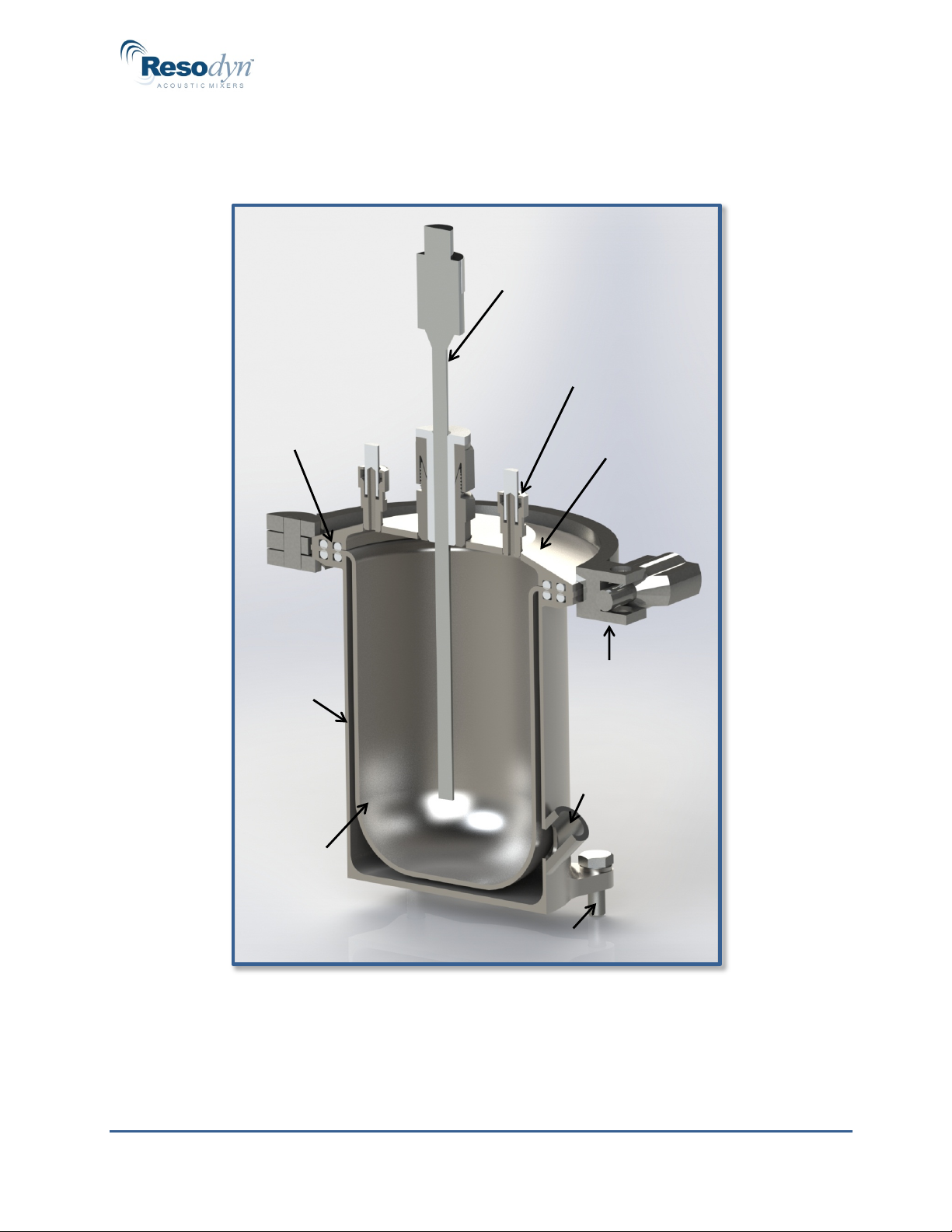
The Resodyn Jacketed Vessel is a processing accessory designed for use with the
Resodyn LabRAM II mixing platform. The Jacketed Vessel allows heating or cooling
before, during, or after the mixing process via heat transfer fluid or “jacket” flowing through
the outer fixture h=enclosing the mixing vessel.
ResonantAcoustic®Mixing (RAM) utilizes acoustic energy to mix liquids, powders,
slurries, and pastes rapidly, efficiently, and thoroughly. Please refer to the Users’ Manual
provided with the LabRAM II mixer for more detailed information about RAM technology
and visit www.resodynmixers.com.
This manual will provide vital LabRAM II Jacketed Vessel information on the following:
•Understanding the major components
•Setting up the Jacketed Vessel hardware
•Safe operation of the Jacketed Vessel using a LabRAM II
•Cleaning and maintenance of the equipment
•Obtaining additional accessories or replacement parts
Key features of the LabRAM II Jacketed Vessel:
•Control of fluid temperature from 0°F cooling to 302°F heating (-18°C to 150°C)
•Facilitates mix quality when temperature control is required
•Access ports to enable use of the vacuum processing option
•Enables temperature monitoring with access port for RTD hardware
•Removable, replaceable mixing vessel liner in multiple sizes
The Jacketed Vessel system provides the following processing advantages:
•Improved mixing results via constant or ramped temperature operation before,
during, or after mixing
•Control of heating/cooling fluid using LabRAM< II’s integrated Operating System
•Recording of vacuum and temperature measurements
•Durable stainless steel construction is compatible with most mixing materials and
coolants, including steam, water, antifreeze, hot oil, etc.
Not covered in this manual are:
•Details, use, operation, or repair of LabRAM II, Pharma RAM II, or LabRAM II H
mixers. Please refer to those manuals for more information
•Heat transfer fluid heating, cooling, circulation, and control systems.
Call 406 497-5333 for more information about heater chiller cooling options

LabRAM II Jacketed Vessel Users’ Manual
DEFINITIONS
Resodyn Acoustic Mixers, Inc. 4 010320
2 Definitions and Abbreviations
Acceleration: A change in velocity with respect to time that is expressed in “g.”
Different mix media mixes at different accelerations, based on the
material and the expected results,
Damping: A term to quantify the instantaneous amount of energy absorbed by the
mix media while mixing.
g: A measure of acceleration expressed as a multiple of the gravitational
acceleration applied to the vessel and mix media during mixing. For
example, 10 gis 10 times the force of gravity. It may also be shown as
gor g’s. Another term that may be used to describe the acceleration is
“gravities.”
Headspace: The volume of compressible air, gas, or void space above the mix
media in the vessel that is not occupied by the mix media.
Mixing Media: Defined as the liquid or solid material inside the mixing vessel.
Mixing Power: The amount of power being delivered by the RAM system to perform
mixing.
Mixing Regime: Specific modes of mixing. For example, a fluid will change regimes as it
undergoes changes in acceleration, from an incompressible liquid
containing few headspace bubbles, to a fluid that is fully integrated with
the compressible headspace such that the two are indistinguishable
from each other.
PTFE: Polytetrafluoroethylene, also known as TeflonTM
RAM: ResonantAcoustic®Mixing or ResonantAcoustic® Mixer.
Resonance: The frequency (nominally 60 Hz) at which the system operates in the
most efficient manner.
RTD: Resistance Temperature Detector used to measure the temperature of
processing materials
Service Loop: A gradual arc in lines and cables connected to the Jacketed Vessel to
accommodate the vertical movement of the LabRAM II mixing platform
during operation.
SS: Stainless Steel
Vacuum: Internal vessel pressure that is less than atmospheric pressure. (If
using vacuum in combination with heating/chilling, please refer the
appropriate Resodyn Vacuum System Manual, or other vacuum utility
in use for processing.)

LabRAM II Jacketed Vessel Users’ Manual
SAFETY INFORMATION
Resodyn Acoustic Mixers, Inc. 5 010320
3 Safety Information
Every effort has been made to assure that the LabRAM II Jacketed Vessel is easy to use,
reliable, and safe. This section outlines the general safety considerations and highlights
important information with caution and warning symbols used throughout this document.
3.1 General Safety and Assembly Considerations
For safe operation, the LabRAM II Jacketed Vessel should be operated only within the
limits outlined in the system specifications. Specifically, the following classification defines
acceptable use and conditions for the LabRAM II Jacketed Vessel:
•0º to 302°F (-18ºC to 150°C) jacket temperature
•-14.7 to 50 psig (0 to 4.5 bar absolute) product vessel pressure
•0 to 50 psig (~1 to 4.5 bar absolute) jacket pressure
•Suitable for intermittent or continuous operation.
•For use in non-hazardous environments or, if used with the LabRAM II H mixing
platform, in hazardous environments as classified by the United States National
Electrical Code (NEC) Class I Div I and Class II Div I.
3.2 Warnings and Cautions
Throughout the manual, the following symbol is used to identify warnings and cautions:
The caution symbol indicates a potential hazardous situation which
could result in minor injury or damage to the product.
3.3 Important Safety Notes
This equipment should only be operated by trained and qualified
personnel with access to and knowledge of the equipment
functions.
Mixing operations can generate heat and internal pressure depending on material and
mixer accelerations. Always pre-test materials and processes. Do not mix materials longer
than what has been characterized as safe.
Note: Changes in noise level or frequency are common during mixing operations.

LabRAM II Jacketed Vessel Users’ Manual
SAFETY INFORMATION
Resodyn Acoustic Mixers, Inc. 6 Rev. 110119
WARNINGS: Failure to properly seal the heat transfer fluid circuit
prior to starting the pump or failure to depressurize the heat
transfer fluid circuit prior to opening may result in leakage of heat
transfer fluid from the circuit. Use appropriate measures to protect
operator and equipment.
Turn heat transfer fluid pump off before removing or installing
tubing or opening the Jacketed Vessel.
CAUTIONS: Use recommended fittings only. Use of improper
fittings and/or improper connection to fittings may result in
leakage at the fittings.
A (user supplied) heat transfer fluid circuit pressure relief/bypass
valve must be installed in a potentially high-pressure system to
prevent the pump from exceeding the maximum rated pressure;
i.e., 50 psig (3.5 bar) for the Jacketed Vessel system.
A (user supplied) product-side pressure relief valve must be
installed (i.e. in the vacuum line) if the LabRAM II Jacketed
Vessel is used in applications where the process pressure inside
the mixer could exceed 50 psig.

LabRAM II Jacketed Vessel Users’ Manual
REPLACEMENT PARTS
Resodyn Acoustic Mixers, Inc. 7 010320
4 General Notes
For use with the LabRAM ll mixer, the Jacketed Vessel assembly consists of:
•Jacket fixture that attaches to the LabRAM II Resonator Plate
•Removable mixing vessel
•Fixture lid with RTD and vacuum ports.
The system bolts into place, replacing the vessel holder on the LabRAM ll and features
ports for an RTD temperature probe port and two vacuum lines. The system’s metallic
surfaces are 316 stainless steel.
4.1 System Description
The LabRAM II Jacketed Vessel accessory consists of the following:
•One 316 stainless steel (SS) Jacketed Vessel fixture with 1/8” female NPT
connections for heating/cooling transfer fluid inlet and outlet
•One 500 ml/16 oz. payload capacity 316 stainless steel mixing vessel
•One 316 stainless steel fixture lid with fittings for vacuum lines and RTD probe
•One stainless steel Sanitary Quick-Clamp
•Four Viton O-rings (two large and two small), required for face seal between
Jacketed Vessel fixture and removable mixing vessel, and between the removable
mixing vessel and Jacket fixture lid.
For O-rings of special materials, please call 406-497-5333
•6” long 316 SS sheathed Resistance Temperature Detector (RTD)
•PTFE RTD sleeve, ½” PTFE front and rear ferrules, and compression nut
•RTD Cable
•Vacuum lines connecting LabRAM II vacuum ports to Jacketed Vessel fixture Lid
•Four tube plugs (for operation without vacuum, includes two extra)
•Four bolts with washers for anchoring the Jacketed Vessel fixture to the LabRAM II
platform
•Two braided SS flex hoses for Jacketed Vessel heating/cooling transfer fluid
service loop connections to back panel of LabRAM II
A cutaway of the LabRAM II Jacketed Vessel system including significant components is
shown in Figure 4-1.
Note: A compatible LabRAM II mixer and heat/cooling transfer fluid supply system are not
included in the Jacketed Vessel components, but are required for its use. Refer to the
user manual for your heater/chiller system for installation and operating instructions. If you
need a heat transfer supply system, please contact Resodyn at 406-497-5333.

LabRAM II Jacketed Vessel Users’ Manual
SAFETY INFORMATION
Resodyn Acoustic Mixers, Inc. 8 Rev. 110119
Figure 4-1. Jacketed vessel cutaway showing the components included in the assembly
(except hoses and cables).
RTD Assembly
Jacketed
Vessel Lid
Vacuum Port
(1 of 2)
Sanitary
Quick-Clamp
Heat Transfer
Fluid Port
Bolt for Mounting on LabRAM II
O-ring
Face-Seals
Mixing
Liner
Jacketed
Vessel
Jacket

LabRAM II Jacketed Vessel Users’ Manual
SAFETY INFORMATION
Resodyn Acoustic Mixers, Inc. 9 Rev. 110119
5 Installation
5.1 Jacketed Vessel Assembly – Component Pictures
Key components of the Jacketed Vessel assembly are shown below. They will be referred
to throughout this manual.
Figure 5-1 shows the main parts of the Jacketed Vessel: the Jacketed
Vessel fixture (inside which heating/cooling transfer fluid flows), the
removable mixing vessel (in which mix materials are added and mixed),
and the Jacketed Vessel fixture lid (with integrated RTD and vacuum
ports).
In Figure 5-2 the fully assembled Jacketed Vessel is pictured mounted
on a LabRAM II mixer resonator plate with all connections attached.
Note that each line or cable attached to the Jacketed Vessel fixture
forms a gradual arc (or service loop) to accommodate the vertical
movement of the LabRAM II mixing platform during operation.
In Figure 5-3 the RTD assembly is shown inserted through the RTD
PTFE sleeve, ½” nut, back ferrule, and front ferrule.
Figure 5-1. Jacketed vessel main components.

LabRAM II Jacketed Vessel Users’ Manual
SAFETY INFORMATION
Resodyn Acoustic Mixers, Inc. 10 Rev. 110119
Figure 5-2. Jacketed Vessel mounted on a Resodyn LabRAM II mixer.
Figure 5-3. RTD assembly, sleeve, nut, and ferrules used to seal the RTD feed.

LabRAM II Jacketed Vessel Users’ Manual
SAFETY INFORMATION
Resodyn Acoustic Mixers, Inc. 11 Rev. 110119
5.2 Jacketed Vessel Accessory Installation and Removal
This section provides instructions for the installation and removal of a Jacketed Vessel on
the LabRAM II.
Make sure the LabRAM II mixer is turned off whenever installing,
manipulating, or removing the Jacketed Vessel assembly.
Carefully remove the existing vessel holder on the LabRAM II machine.
Locate the four bolt holes for mounting the Jacketed Vessel fixture on the
LabRAM II (Figure 5-2) payload plate.
Attach the Jacketed Vessel fixture to the payload plate using the four
mounting bolts. The washers should be installed between the bolt heads
and Jacketed Vessel fixture mounting feet, one on each foot, with the
orientation shown in Figure 5-2. Torque to 76 in-lbf (8.6 N-m).
Connect the stainless steel flex hoses to the Jacketed Vessel by threading
the male NPT fitting on the end of one hose into each of the female NPT
fittings on the outside of the Jacketed Vessel fixture. Apply thread sealant to
ensure a leak-free connection.
Install the O-Rings in the Jacketed Vessel fixture. For the large O-Ring
groove use the large O-Ring (part number 003306) and use the small O-
Ring (part number 003305) in the small O-Ring groove.
Attach each of the Heat Transfer Fluid Hoses to the back panel of the
LabRAM II mixer as shown in Figure 5.2. The Jacketed Vessel should work
equally well regardless of the direction of flow, but if a specific flow direction
is desired, note the hose locations.
Place the removable Mixing Vessel on top of the now mounted and installed
Jacketed Vessel fixture.
Place an O-Ring in each of the two O-Ring grooves of the fixture lid. For the
large O-Ring groove use the large O-Ring (part number 003306) and use
the small O-Ring (part number 003305) in the small O-Ring groove.
NOTE: Applying a thin layer of vacuum grease (customer supplied) on each
O-Ring in the Lid will provide better vacuum. Verify any material is
compatible with the vessel and the materials being processed.
Place the Jacketed Vessel fixture lid over the broad, removable Mixing
Vessel rim, orienting the vessel lid so that vacuum ports form a parallel line
with the back panel (see Fig 5.2). Use the Sanitary Quick-Clamp to clamp
the lid in place, tightening the clamp nut until the clamp is hand tight.
Insert the PTFE Sleeve for the RTD through the hole in the center of the
Compression Nut and Rear and Front Ferrules (as shown in Figure 5.3),
with the wide rim on top of the nut. Insert the RTD tip through the hole in the
center of the PTFE sleeve (Figure 5.3) and mount this assembly onto the
fitting on the top of the Jacketed Vessel fixture lid as shown in Figure 4.1.
Do not cross-thread the fittings or damage the ferrules.

LabRAM II Jacketed Vessel Users’ Manual
SAFETY INFORMATION
Resodyn Acoustic Mixers, Inc. 12 Rev. 110119
Adjust the RTD height until the tip extends the desired distance from the
bottom of the lid to the desired depth into the removable Mixing Vessel. If
the RTD does not slide easily through the PTFE Sleeve, loosen the
Compression Nut.
Attach the L shaped end of the RTD cable to the back panel. The cable will
be pointed upward when properly attached to the back panel. Hand tighten
the connection.
Orient the RTD connector to align with pins in the RTD, push gently into
place, and tighten the nut to attach the RTD Cable to top of the RTD. Take
care not to damage the pins inside the RTD. Rotate the RTD until all twists
are removed. The RTD cable should form a smooth service loop similar to
the one shown in Figure 5.2.
Make sure to rotate the RTD cable to eliminate any twists.
Leaving twists in the cable length will reduce the life of the cable
and may reduce the life of the RTD
Tighten the Compression Nut on the Jacketed Vessel fixture lid until the
RTD is held snugly in place at the desired depth. The RTD should not slide
up or down relative to the Jacketed Vessel lid during resonant acoustic
mixing at high (i.e. 100 g) accelerations.
If process vacuum is to be used, loosen the white compression nuts in the
back panel and thread each of the Vacuum Lines from the vacuum unit
through the back of the panel to form a gradual 90 degree arc (service loop)
down to the Jacketed Vessel fixture lid as shown in Figure 5.2.
Attach the Vacuum Lines to the compression fittings in the Jacketed Vessel
Lid by inserting the tubing as far into the lid as possible without forcing, and
tightening the compression nut. Then hand-tighten the white compression
nuts on the back panel, ensuring that the tubing forms a smooth arc as
pictured in Figure 5.2.
If process vacuum is not to be used, insert a PTFE Tube Plug (part number
102665) into the vacuum and sensor compression fittings on top of the lid.
Note that 2 spare Tube Plugs are included with the unit for times that the
vacuum lines are not connected.
With the Jacketed Vessel assembly clamped closed, check the vacuum and
heating/cooling transfer fluid circuits at full pressure and flow rate to make
sure they do not leak. Fix any leaks prior to use.
Isolate the Jacketed Vessel assembly from the vacuum pressure (if used)
and heating/cooling transfer fluid supply pressure (e.g. turn off the heat
transfer fluid pump).

LabRAM II Jacketed Vessel Users’ Manual
SAFETY INFORMATION
Resodyn Acoustic Mixers, Inc. 13 Rev. 110119
If the Jacketed Vessel is not isolated from the heating/cooling
transfer fluid supply pressure before unclamping the Jacketed
Vessel, heat transfer fluid will leak out onto the mixer platform.
Removal is the reverse of installation. Be sure to isolate the Jacketed
Vessel from the vacuum pressure (if used) and heating//cooling transfer
fluid supply pressure (e.g. turn off the heat transfer fluid pump) as the first
step. When removing the mix liner, some heat transfer fluid may drip from
the mix liner. It may also be extremely cold or hot. Use proper PPE.
When removing the mix liner, some heat transfer fluid will drip off
the mix liner, it may be extremely cold or hot. Use proper PPE.
•.
6 Operating Instructions
6.1 LabRAM II Jacketed Vessel Accessory Operation
Isolate the Jacketed Vessel from the vacuum pressure (if used) and
heating/cooling transfer fluid supply pressure (e.g. turn off the heat transfer
fluid pump).
If the Jacketed Vessel is not isolated from the heating/cooling
transfer fluid supply pressure before unclamping the Jacketed
Vessel, transfer fluid will leak out onto the mixer platform.
Loosen and remove the Sanitary Quick-Clamp and remove the Jacketed
Vessel fixture lid from the Jacketed Vessel fixture.
Add any ingredients you will be mixing to the removable Mixing Vessel (and
if appropriate, place the Mixing Vessel back inside the Jacketed Vessel
fixture making sure the O-rings are in place).
Replace the lid (with O-rings in place) on top of the removable Mixing
Vessel and use the Sanitary Quick-Clamp to clamp the lid in place,
tightening down the clamp nut until the clamp contacts the Jacketed Vessel
fixture around the entire perimeter and the clamp is hand tight.
Begin flowing or circulating heating/cooling transfer fluid through the
Jacketed Vessel and allow the system to come to the desired mixing
temperature. If any leaks are observed in the system, stop the flow and fix
the leaks.

LabRAM II Jacketed Vessel Users’ Manual
SAFETY INFORMATION
Resodyn Acoustic Mixers, Inc. 14 Rev. 110119
Use the LabRAM II and vacuum pump (if used) to perform the desired
processing (see LabRAM II users’ guide and vacuum pump manual for
operating directions).
Once the mixing is completed, isolate the Jacketed Vessel assembly from
the vacuum pressure (if used) and heating/cooling transfer fluid supply
pressure (e.g. turn off the heat transfer fluid pump).
If the Jacketed Vessel is not isolated from the transfer fluid supply
pressure before unclamping the Jacketed Vessel, transfer fluid will
leak out onto the mixer platform.
Loosen and remove the Sanitary Quick-Clamp and remove the Jacketed
Vessel fixture lid from the removable Mixing Vessel to recover the
processed material. Take care not to contaminate the materials with the
transfer fluid from the underside of the Mixing Vessel liner.
7 Service Information
7.1 Maintenance and Service
The LabRAM II Jacketed Vessel accessory should only be operated when it is in good
working condition. If the system shows any signs of visible damage or fails to operate as
outlined in this manual, the system should not be operated.
If necessary, contact your Resodyn Acoustic Mixers customer service representative for
questions or additional technical support related to the mixer.
Technical Support for Mixer and Jacketed Vessel Operation and Maintenance:
Phone: (406) 497-5333
Fax: (406) 497-5206
e-mail: [email protected]
Resodyn Acoustic Mixers
130 North Main, Suite 630
Butte, Montana 59701

LabRAM II Jacketed Vessel Users’ Manual
SAFETY INFORMATION
Resodyn Acoustic Mixers, Inc. 15 Rev. 110119
8 Supplemental Information
8.1 Replacement Parts
Item Quantity
Part
Number
Description
1 1 102759 Jacketed Vessel Jacket
2 1 2805 Sanitary Quick-Clamp,
3 4 2806 Washer, 1/4"
4 1 3306 O-Ring, Large, Viton
5 1 3305 O-Ring, Small, Viton
6 4
A01A-
0250-20-
00750-ABB
1/4" Hex Head Bolt
7 1 102760
Mixing Liner, 16 oz.,
Stainless
8 1 102761 Jacketed Vessel Lid
9 1 102784 RTD PTFE Sleeve
10 1 3305 O-Ring, Small, Viton
11 1 3306 O-Ring, Large, Viton
12 1 903345 RTD Cable (not shown)
13 1 903324 RTD Assembly, 6” Probe
14 1 2956 1/2" PTFE Ferrule Set
15 4 102665 Tube Plug, PTFE
16 2 1339
Heat Transfer Fluid Hose
for Service Loop (not
shown)
17 2 3285
Antistatic Tubing for
Vacuum Lines (not
shown)
Figure 8-1: LabRAM II Jacketed Vessel Components
Other manuals for LabRAM II
2
Table of contents
Other Resodyn Laboratory Equipment manuals
Popular Laboratory Equipment manuals by other brands

VWR
VWR peqlab PCR Workstation Pro instruction manual

Metrohm
Metrohm 893 manual

Drucker Diagnostics
Drucker Diagnostics Horizon 6 FA Service manual

Elster Instromet
Elster Instromet enCore FC1 manual

Haag-Streit
Haag-Streit LI 900 Instructions for use

Cost Effective Equipment
Cost Effective Equipment Apogee 450 Operation manual