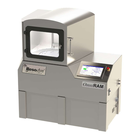
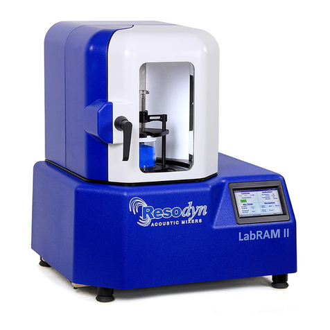
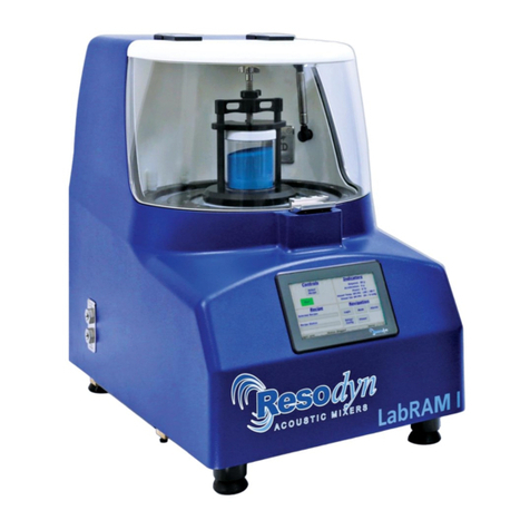
Resodyn LabRAM II H User manual

Resodyn Acoustic Mixers 130 N. Main Street Butte, MT 59701 406-497-5333 www.resodynmixers.com
LabRAM II H
Installation
and Users’
Manual

Resodyn Acoustic Mixers Rev 062520
Notes & Information
Date of Purchase
Date of Installation
Pilot Testing
Production Start
Maintenance Record

1
Resodyn Acoustic Mixers Rev 062520
Table of Contents
1Introduction .................................................................................................................... 3
2Definitions ...................................................................................................................... 3
3Safety............................................................................................................................. 6
3.1 General Safety Considerations .................................................................................... 6
3.2 Warnings and Cautions................................................................................................ 6
3.3 Hazardous Location Notes........................................................................................... 7
3.4 Component Replacement ............................................................................................ 7
3.5 Customer Responsibility .............................................................................................. 8
3.6 Handling/Lifting ............................................................................................................ 8
3.7 Mounting...................................................................................................................... 9
3.8 Guards and Safety Devices ......................................................................................... 9
3.9 Technical Support for Mixer Operation:.......................................................................10
4System Overview ..........................................................................................................11
4.1 ResonantAcoustic®Mixing Platform ............................................................................12
4.2 Acoustic Enclosure .....................................................................................................12
4.3 Remote Panel and Touch Screen Human Machine Interface (HMI) ............................12
4.4 Standard Vessel Fixture and Vessels..........................................................................13
5System Specifications ...................................................................................................14
5.1 Voltage Level ..............................................................................................................14
5.2 Power Consumption....................................................................................................15
6Installation .....................................................................................................................15
6.1 Unpacking, Lifting, and Placing LabRAM II H..............................................................15
6.2 Mounting.....................................................................................................................15
6.3 Remove the Shipping Lock Bar...................................................................................16
6.4 Vessel Holder Assembly .............................................................................................16
6.5 Purge System .............................................................................................................18
6.6 Electrical Installation ...................................................................................................19
6.7 Purge Air Connections ................................................................................................20
6.8 Machine Cooling Connections.....................................................................................20
6.9 Fiber Optic Communication.........................................................................................21
6.10 Temperature Measurement and RTD and Vacuum Line Holder Option ......................22
6.11 Jacketed Vessel and Jacketed Vessel Plumbing (Option)...........................................23
6.12 Vacuum Control System (Option)................................................................................26
6.13 Remote USB Connection (Option) ..............................................................................27
7Quick Start ....................................................................................................................28
7.1 Setup ..........................................................................................................................28
7.2 Power-Up....................................................................................................................28

2
Resodyn Acoustic Mixers Rev 062520
7.3 Login...........................................................................................................................31
7.4 Select the Recipe........................................................................................................32
7.5 Run the Recipe ...........................................................................................................33
7.6 Completion .................................................................................................................33
8HMI (Human Machine Interface) – Overview .................................................................34
8.1 Main Screen................................................................................................................34
8.2 Login...........................................................................................................................35
8.3 Alarming .....................................................................................................................35
8.4 Setup and Configuration Screens ...............................................................................35
8.5 Viewer.........................................................................................................................35
9HMI Operation – Security and Login..............................................................................36
9.1 Login Levels and Privileges ........................................................................................36
9.2Screen Operations - Logging In/Out............................................................................36
9.3 Log Files .....................................................................................................................37
10 HMI Operation – Modes of Operation ............................................................................38
10.1 Screen Operations - Recipe Mode ..............................................................................38
Screen Operations - Auto Mode ............................................................................................41
11 HMI Operation – Alarming .............................................................................................45
11.1 Screen Operations - Alarms........................................................................................45
12 HMI Operation – Viewer ................................................................................................47
12.1 Screen Operations - Viewer ........................................................................................47
13 HMI Operation – Setup and Configuration .....................................................................48
13.1 Status Tab ..................................................................................................................50
13.2 Calibration Tab ...........................................................................................................50
13.3 Recipe Tab .................................................................................................................50
13.4 Setup1 Tab .................................................................................................................58
13.5 Setup2 Tab .................................................................................................................59
13.6 Setting Date and Time ................................................................................................61
13.7 Config Tab ..................................................................................................................61
Data Tab ...............................................................................................................................65
14 Care and Maintenance ..................................................................................................66
14.1 Preventive Maintenance .............................................................................................66
14.2 Cleaning Procedures ..................................................................................................66
14.3 Accelerometer Calibration...........................................................................................66
14.4 Maintenance ...............................................................................................................66
14.5 Replacement of Serviceable Parts ..............................................................................67
15 Troubleshooting and Service .........................................................................................71
Appendices A Electrical Installation.......................................................................................... A
Appendices B Component Arrangement ..................................................................................G

3
Resodyn Acoustic Mixers Rev 062520
1 Introduction
ResonantAcoustic® Mixing (RAM) is an advanced mixing/processing technology that is the only
technology that uses low-frequency acoustic energy for mixing and processing. The RAM 5 is
an innovative approach to multiple mixing applications from pilot to production scale. These
applications include powder-powder systems, powder-liquid systems and liquid-gas systems, as
well as combinations thereof. The technology has also been adopted for use in many
processing functions, such as coating, degassing, grinding and sieving.
The RAM system provides:
•Exceptionally uniform mixing and/or processing of virtually any materials.
•Significantly faster mixing and processing times than traditional methods.
•Completely sealed, dust-free process resulting in cleanliness and enhanced operator
safety.
•Highly repeatable results, ensuring batch-to-batch product consistency and quality.
•The ability to process materials not possible by other methods.
RAM Operations
The primary driving mechanical driver of RAM mixing technology is Acceleration (rate of change
of velocity). The unit of measure of acceleration in the International System of Units (SI) is
meters per second squared or m/s2. A familiar way to describe this phenomenon is the
acceleration of gravity here on earth or g. One gis the acceleration of gravity at the Earth's
surface and uses the standard gravity symbol: g, defined as ~9.81 meters per second squared.
The acceleration is generated by vertical motion of the mixing/processing vessel configured in a
RAM machine. This vertical, sinusoidal motion operates at a frequency of between 58 and 62
Hz and at a peak displacement of up to 0.55” when operated at 100 g. The combined low-
frequency vibration and resulting displacement creates a physical mixing and processing motion
that is, uniform, repeatable, intense, yet low shear.
All RAM systems operate at this frequency range in a resonant condition, which enables a
process that requires low levels of energy for operation. The resonant condition of the system is
established over a range of frequencies that enables a balance between the kinetic energy of
the springs and potential energy of the oscillating plates that comprise the resonator platform.
The materials being mixed are the impedance for the resonant system.
When the system is operating at resonance, virtually all of the energy from the system motors is
applied directly to the materials being mixed and/or processed, resulting in a very energy
efficient system. This resonant condition is frequency dependent and requires the frequency to
allow a near perfect balance between the kinetic energy forces, the potential energy forces and
the impedance of the process. Both the kinetic and potential energy forces are set by the
system design, but the impedance depends upon the nature of the process that is contained in
the mixing/processing vessel that is agitated by the plate/spring resonator. Moreover, as the
materials properties in the processing vessel change properties the impedance to the system

4
Resodyn Acoustic Mixers Rev 062520
changes, which requires careful control and adjustment of the system frequency in order to
keep the RAM system at resonance. This operating frequency is automatically sensed and
controlled by a proprietary system/methodology that is an integral feature of the RAM
technology. The system/methodology continuously and automatically adjusts to changes in the
mixing/processing conditions within the mixing vessel or processing container. The continuous
maintenance of the resonant operation provides both power and economy to all RAM devices.
RAM Processing Parameters
RAM’s mixing platform’s intense vertical motion also generates acoustic effects within the
mixing vessel. This “sound mixing” has different effects on different materials that are being
processed.
In addition to the vessel acceleration, g, other salient factors that affect the mixing and/or
processing performance include pressure inside of the mixing/processing vessel (which can
range from vacuum to pressurized), temperature of the vessel contents, vessel design and
processed material fill height of the vessel, as well as order of material addition to the vessel for
some processes.
For more information on the basics and practice of RAM technology, visit the Resodyn website
at www.https//ResodynMixers.com, or contact Resodyn at 406 497-5333.
RAM Product Line
When considering the entire RAM product family, it is important to recognize that, generally
speaking, the processing settings used for a particular material performs the similarly across all
RAM technology platforms. This means that a finding of optimal settings on the bench scale
LabRAM I or LabRAM II mixers is nominally equivalent to those that would be used to process
the same materials on the OmniRAM, RAM 5, or RAM 55 mixers. As such, transition from
discoveries made in the laboratory to the pilot, or product scale are seamless for most
processes.

5
Resodyn Acoustic Mixers Rev 062520
2 Definitions
Acceleration: A change in velocity with respect to time that is expressed in terms of “g.”
Different ingredients mix at different accelerations, based on the material and
other processing variables. (See “g” below.)
Damping: A term to quantify the instantaneous amount of energy absorbed by the mix
media while mixing
g: A measure of acceleration expressed as a multiple of the gravitational
acceleration applied to the vessel and its ingredients during mixing. For
example, 10 gis 10 times the force of gravity. Other terms are “g” and
“gravities.” (See “Acceleration” above.)
HMI: Human Machine Interface. The control and input system screen used to
operate RAM devices
Headspace: The volume of compressible air, gas, or void space that is otherwise not
occupied above the mixing media in the vessel
Millibar Or mbar, is unit of air pressure in the metric system based on an absolute
scale. This method displays the same measure regardless of altitude
Mixing Ingredients: Defined as the material inside the mixing vessel
Mixing Power: The amount of power being delivered by the RAM system to perform mixing
in terms of watts per kilograms
Mixing Regime: This term identifies certain modes of mixing. The mixing regime defines the
bulk flow pattern of the media during mixing. A regime changes when the bulk
patterns change. For example, a stable fluid mixing regime for thick pastes
would be one that flows from the bottom of the vessel up the center and then
across the top and down the sides. Another regime is indicated by a paste
mix that is fully coupled to the sides of the mixing vessel and does not move.
NEC: National Electrical Code, or National Fire Protection Association (NFPA) 70
RAM: ResonantAcoustic®Mixing or ResonantAcoustic®Mixer
Resonance: A condition (nominally at 60 Hz for RAM devices) at which the RAM
mechanical system operates in the most powerful and efficient manner
Torr: Units of vacuum used on Resodyn Manual Vacuum pressure based on an
absolute scale. This method displays the same measure regardless of
altitude.
Vacuum: Internal vessel pressure that is less than atmospheric pressure.

LabRAM II H Operations Manual
Safety
6
Resodyn Acoustic Mixers Rev 062520
3 Safety
Every effort has been made to assure that the LabRAM II H is easy to use, reliable, and safe.
This section outlines the general safety considerations and defines caution and warning
symbols used throughout this manual.
3.1 General Safety Considerations
For safe operation, the LabRAM II H should be operated only within the limits outlined in the
system specifications. The following classification defines acceptable use for the LabRAM II H.
•Indoor use only.
•Main supply voltage fluctuations do not exceed ±10% of the nominal supply voltage.
•This equipment is suitable for continuous operation.
•For use in non-hazardous and hazardous environments that are Class I Div I, and
Class II, Div 1 and 2, Groups C-G as classified by the United States National
Electrical Code (NEC).
3.2 Warnings and Cautions
Throughout the manual, the following symbols are used to identify warnings and cautions:
The caution symbol indicates a potential hazardous situation which could result in
minor injury or damage to the product.
The high voltage symbol indicates the possibility of electrical shock.
This symbol means turn off the electrical supply before removing any cover with
the symbol attached. Failure to do so may cause exposure to electrical shock
hazard.
Access to electrical components should only be carried out by a licensed
electrician or qualified electrical engineer.
NEVER attempt to modify any electrical components or circuits as this may affect
the safe operation of the machine.
Electrostatic Discharge (ESD) sensitive components.

LabRAM II H Operations Manual
Safety
7
Resodyn Acoustic Mixers Rev 062520
Important Safety Notes
This equipment should only be operated by trained and qualified personnel.
Mixing operations can generate heat and internal pressure depending on material
and may be affected differently at varying mixer accelerations. Do not mix materials
longer than what has been characterized as safe.
Do not attempt to run the machine without a mix container or vessel holder.
Equipment damage may result.
Do not disable or tamper with any safety items, such as safety interlock switches
located on the LabRAM II H system.
Note: Changes in noise level or frequency are common during mixing operations. If
rattling, metal-on-metal, or obnoxious noises occur, turn off the LabRAM II H and
call or email the Resodyn Acoustic Mixers Technical Support. (406) 497-5333
3.3 Hazardous Location Notes
The LabRAM II H system is designed to be operated in Class I Div I, and Class II, Div 1 and 2,
Groups C-G. The purge controller ensures that adequate positive air pressure is present inside
of the LabRAM II H unit, before power is applied to internal electronics.
3.4 Location Advisory
3.5 Component Replacement
The system is designed with components that are specifically rated for use with the LabRAM II
H machine. Only replace worn or damaged components with direct factory replacement parts or
parts approved by Resodyn Acoustic Mixers. Incorrect component replacement can impair the
safety of the equipment and risk injury to personnel.
The LabRAM II system is designed to be operated in non-hazardous environments.
The LabRAM II system is protected by an IP20 enclosure which is not rated for
operation in dusty environments.
The LabRAM II system is rated for operating in ambient environments between 0°C –
40°C (32°F – 104°F).
Do not replace components with non-factory components. Non-factory replacement
parts may not be rated to be used to the LabRAM II H machine requirements, which
will compromise the safety of the operating personnel and may cause damage to the
equipment.

LabRAM II H Operations Manual
Safety
8
Resodyn Acoustic Mixers Rev 062520
3.6 Customer Responsibility
•Ensure that all operators have received the correct training to operate the mixer.
•Ensure that all operators have read and understood this instruction manual.
•Ensure that a qualified electrician carries out any electrical maintenance.
•Allow only Resodyn Acoustic Mixers Service Engineers to repair a LabRAM II H or
return to Resodyn after receiving a Return Authorization.
3.7 Handling/Lifting
Upon receipt of the LabRAM II H, do not unpack or remove any of the packaging materials until
positioned as close to the installation location as possible. When in position, carefully follow the
instructions in the section below.
Retain all packaging for 1 year should machine movement or unexpected warranty service be
necessary. Original packaging will be required for service shipment during the warranty period
and is highly recommended for any shipment performed during the entire life of the product.
•The LabRAM II H should only be handled by multiple, experienced material handling
or rigging personnel.
•DO NOT use lifting accessories around or attached to parts that may be damaged or
fail during lifting.
•DO NOT use lifting accessories around sharp edges that may damage the item and
cause the machine to fall.
•DO exercise caution when lifting and moving the equipment to avoid striking other
objects.
The LabRAM II H mixer is 350 lbs. with no additional options. The mixer should be lifted using a
forklift. The LabRAM II H was packaged in a wooden crate and should be removed from the
crate by performing the following instructions:
1. Release the shipping strap and remove along with the protective foam under the shipping
strap.
2. Lift the LabRAM II H, by using the forklift forks in the fork locations shown below. The
LabRAM II H machine can now be placed on an appropriate mounting surface.
Insert Forks
Strap
Strap Release

LabRAM II H Operations Manual
Safety
9
Resodyn Acoustic Mixers Rev 062520
All non-permanent options, such as the vessel holder fixture, fiber
cable, remote control enclosure, remote disconnect enclosure,
jacketed vessel, etc., have been shipped in separate boxes and
are placed on the top tier of the wooden crate, as shown.
3.8 Mounting
The LabRAM II H should be installed on a stable rigid surface
capable of supporting the weight of the mixer. The LabRAM II H
should be mounted on top of a table, making sure that all 5
support feet illustrated below are present.
3.9 Guards and Safety Devices
Ensure all safety devices (limit switches, etc.) are functioning correctly, and regularly check their
operation.
Do not attempt to lift or carry the LabRAM II H with a single person or multiple
people. Only lift the equipment with proper lifting equipment and methods.
Mounting Feet Locations

LabRAM II H Operations Manual
Safety
10
Resodyn Acoustic Mixers Rev 062520
3.10 Technical Support for Mixer Operation:
The LabRAM II H system should only be operated when it is in good working condition. If the
system shows any signs of visible damage or fails to operate as outlined in this manual, the
system should not be operated.
For operational errors and troubleshooting, refer to Troubleshooting, Section 15, Page 71.
If necessary, contact your Resodyn Acoustic Mixers customer service representative for
questions or the contacts provided below for additional technical support.
Technical Support for Mixer Operation:
Phone : (406) 497-5333
Fax : (406) 497-5206
E-mail :
service@resodynmixers.com
Resodyn Acoustic Mixers
130 North Main, Suite 630
Butte, Montana 59701

LabRAM II H Operations Manual
System Overview
11
Resodyn Acoustic Mixers Rev 062520
4 System Overview
The LabRAM II H is specifically designed and
manufactured for use in mixing up to 2.2 lbs. (1 kg)
of materials. The LabRAM II H is a highly versatile
mixing system that is designed for hazardous area
laboratory and production environments. The
LabRAM II H system is equipped with proprietary
mixing control circuitry, a vessel holder, machine
safety interlocks, purge system, and a stainless steel
acoustic enclosure. The LabRAM II H external features
include the Acoustic Enclosure, Remote Purge Controller,
Remote Control with Touch Screen Human Machine
Interface (HMI), Electrical Connectors and Fuse Access
Panel, and Internal Liquid Cooled Heat Exchanger. For
more information see Appendix B.
The Remote Control, Remote Disconnect, Remote Vacuum Starter, Vessel Heater Cooler, and
Machine Chiller are not designed or rated to be operated in a hazardous area. These devices
cannot be installed in the Hazardous Area.
The Remote Control is connected to the LabRAM II H machine through both the Emergency-
Stop cable and fiber optic communication cables for HMI Touch Screen control and USB
interface.
The Remote Control, Remote Disconnect, Remote Vacuum Starter, Vessel
Heater Cooler, and Machine Chiller are not designed or rated to be operated in a
hazardous area. These devices shall not be installed in the Hazardous Area.
Acoustic
Enclosure
8”
12”
13.5”
Remote Control
Cooling
Inlet/Exit
Front View
Vessel Fixture
Electrical Connections
Purge Vent
Acoustic
Enclosure
Fiber
Connectors
Fuses
Purge Vent Signal

LabRAM II H Operations Manual
System Overview
12
Resodyn Acoustic Mixers Rev 062520
Additional options for the LabRAM II H are heating and cooling plumbing for a jacketed vessel,
vacuum control, remote USB access and temperature monitoring, as well as custom vessel
fixtures, and other custom options.
4.1 ResonantAcoustic®Mixing Platform
The LabRAM II H delivers energy to the material being mixed by accelerating the platform up to
100 gof acceleration, as well as the sound energy created by that motion.
4.2 Acoustic Enclosure
The acoustic enclosure surrounds the patented resonator system. The enclosure reduces the
sound emitted by the LabRAM II H but does not cover the upper resonator plates and gaskets.
Because the moving parts on top of the resonator are not contained in the acoustic enclosure,
the movement of these plates could pose a risk to operators and also generates sound above
80 dB at the machine.
During operation the Payload Plate, Driver Plate, Fixture, and Vessel are accelerating
up to 100 gof acceleration at nominally sixty times per second (60 Hz). Serious bodily
injury is possible if one comes into contact with these moving surfaces.
4.3 Remote Panel and Touch Screen Human Machine Interface (HMI)
The remote panel HMI is the primary user interface on the LabRAM II H. The LabRAM II H is
digitally controlled through the HMI. All data entry and operations are provided through software
keypads and buttons on the screen. The touch screen and operating system is described below
in more detail in Section 8 HMI (Human Machine Interface) – Overview
.
HMI Touch
Screen

LabRAM II H Operations Manual
System Overview
13
Resodyn Acoustic Mixers Rev 062520
4.4 Standard Vessel Fixture and Vessels
A variety of vessel sizes and types, along with the appropriate hold-down fixtures are available
for the LabRAM II H. The standard and supplied vessel hold-down fixture is a 5” diameter vessel
holder that accommodates vessels between the heights of 4.5” and 7”. For vessels shorter than
4.5”, spacers can be purchased from Resodyn Acoustic Mixers as well as shorter standoffs and
bolts that will accommodate vessel heights between 2.5” and 5.25”. Many applications call for
specialized, custom hold-down fixtures. Resodyn can provide virtually any shape of vessel a
particular mixing application requires. Please contact your Resodyn Acoustic Mixer sales
representative to learn more. (406) 497-5333
The LabRAM II H hold-down fixture is made of several key components. All components are
made from electrically conductive or static dissipative materials. These are the hold-down knob,
jam nut, cross bar, bolts, standoffs, upper base, lower base, and upper and lower dots shown
above in sequence and described in more detail below.
Hold-down Knob. Turning the Hold-down Knob clockwise clamps the vessel in place. The knob
is coupled to specialized thread designed for strength and accuracy. The thread is connected to
the Upper Base. Turning the knob raises and lowers the Upper Base.
Jam Nut. The Jam Nut is used to lock the vessel in place. When tightened against the top of the
Cross Bar, the Jam Nut locks the Hold-down Knob from loosening during operation. The Jam
Nut is set after the mixing vessel is tightened down using the Hold-down Knob.
Vessel Spacer Vessel Spacers (not shown) accommodate smaller vessel heights in the
standard height vessel holder. Shorter vessels may require one or more spacers stacked
together. Any mixing vessel must be securely positioned within the upper and lower bases of
the hold-down fixture by RAM Vessel Spacers only. If the mixing vessel is not secure in the
vessel holder, damage may occur to the machine, vessel, and the mixing material. If you require
vessel spacers, please contact your Resodyn Acoustic Mixers sales representative. (405) 497-
5333.
Holder with Mixing
Vessel in Position
Hold Down Knob
Cross Bar
Jam Nut
Upper Base
Standoffs
Upper Dot
Lower Dot
Lower Base
Vessel Holder

LabRAM II H Operations Manual
System Specifications
14
Resodyn Acoustic Mixers Rev 062520
5 System Specifications
The LabRAM II H is equipped with the following external connectors: 1) Hazardous rated
connections for the Inlet power, Emergency-Stop, and Key Controller, 2) USB Option rated for
hazardous environments 3) Fuse Access Cover, 4) Machine Cooling Fluid Connectors, 5) Panel
for Vacuum Option, and 6) Fiber Communication Connectors. All external connections are found
on the stainless acoustic enclosure of the LabRAM II H machine. See Section 4, System
Overview, Page 11 for detailed illustrations.
The LabRAM II H overall system specifications are provided in Table 5-1.
Table 5-1. LabRAM II H System Specifications
Maximum Payload Capacity
2.2 lb. (1 kg)
Sealed Enclosure
Yes (Standard)
Sound Emitted
<70 dB at 3 feet (0.9 m) at 100 g with an empty vessel
Vessel Temperature Monitoring
Up to 2 RTDs monitored and recorded (Optional)
Automatic Programmable Vacuum
Yes (Optional)
Data Logging
Yes (Standard)
Remote Operation
Yes (Standard)
Computerized Operator Interface
Yes (Standard)
Weight
350 lbs. / 400 lbs. with acoustic enclosure
(159 kg / 182 kg with acoustic enclosure)
Overall Dimensions (Clearance)
LabRAM II H Machine
(width x depth x height)
35” x 27” x 28” (0.89 m x 0.69 m x 0.71 m) including
RTD Vacuum Line Bridge
LabRAM II H Remote Box
(width x depth x height) 13.5” x 12” x 8” (0.35 m x 0.31 m x 0.21 m)
Purge & Pressure Control Unit
9” x 6.5” x 14.5” (0.23 m x 0.16 m x 0.37 m)
Electrical @ 50/60 Hz, CE Certified
100-120 VAC / 200-240 VAC
Purge Air
20-120 psi (1.4-8.3 bar) at 12 SCFM (240 l/min)
Cooling Fluid
0.5 gpm (2 l/min) at 60°F (15.5°C) at 0-15 psi (0-1 bar)
NOTE: The LabRAM II H system weighs a minimum of 350 lbs. Follow the
lifting procedures are described in Section 3.6 Handling/Lifting. The system
should be located on a sturdy table or bench that will hold the mixer and any
auxiliary equipment, supplies or loads.
5.1 Voltage Level
The LabRAM II H is designed to utilize single phase 100-120 or 200-240 VAC 50Hz/60Hz
supply voltages for use worldwide. Systems are configured for either 100-120 VAC or 200-240
VAC 50Hz/60Hz supply from the factory.

LabRAM II H Operations Manual
System Specifications
15
Resodyn Acoustic Mixers Rev 062520
5.2 Power Consumption
The mixer is designed to be very efficient by operating at a resonant condition. Depending on
the operating set point, vessel selection, and vessel contents, the LabRAM II H will draw
between 80 and 1200 Watts.
6 Installation
6.1 Unpacking, Lifting, and Placing LabRAM II H
Upon receipt of the LabRAM II H, do not unpack or remove any packaging materials until
positioned as close to the installation location as possible. When in position, remove all
wrapping and strapping, and retain shipping paperwork for your records. Retain all packaging
material for 1 year should machine movement or unexpected warranty service be necessary.
Original packaging will be required for return shipment if service requires it.
•Open the indicated side of the wooden crate and remove any packing materials, bubble
wrap, shipping straps as outlined in Section 3.6 on page 8.
•Make sure to remove any loose packaging material from the area before attempting to
move or install the LabRAM II H
•Following the lifting and moving procedures outlined in Section 3.6 on page 8, move and
install the LabRAM II H machine to the installation location.
•When placing the LabRAM II H at its location, allow enough room around the machine to
complete the installation, route wires and conduit, and allow for future working space,
etc.
6.2 Mounting
The LabRAM II H should be installed on a stable, rigid surface capable of supporting the
machine weight. If other equipment or materials are to be placed or used on the same surface,
a higher weight rating should be used as appropriate.
ResonantAcoustic®Mixing (RAM) technology imparts minimal forces to the surface on which it
is mounted. Careful placement and leveling by a qualified technician is recommended, as is
periodic inspection of the positioning and condition of the surface. Surrounding instruments and
accessories, and mixing conditions should be considered in an overall placement plan.

LabRAM II H Operations Manual
Installation
16
Resodyn Acoustic Mixers Rev 062520
6.3 Remove the Shipping Lock Bar
The LabRAM II H is shipped with a Lock Bar to secure the resonator during transportation. The
Lock Bar MUST be removed before proceeding with installation or attempting to operate the
LabRAM II H.
Remove the 3/16” Allen wrench from its shipping bag attached to the Warning Label. Using the
provided Allen Wrench, remove the two ¼-20 socket head cap screws securing the lock bar
across the mixing platform. Remove the Lock Bar by lifting it from the platform and retain it
along with screws for future re-positioning or transport of mixer. A Resodyn case is provided for
your documentation, manuals, and other materials like this hardware.
Once the shipping bracket has been removed, the vessel holder assembly can now be installed
using the instructions that follow.
6.4 Vessel Holder Assembly
Remove the Vessel Holder Assembly from the accessory box accompanying the shipment.
NOTE: The Hold-Down Fixture is shipped with nuts fastened to the bottom of the ¼-20 socket
head cap screws. These nuts hold the fixture together during shipment. Remove these two nuts
and store them with other hardware. Be careful NOT to remove or change the orientation of the
components until familiar with the parts and the assembly.
Use Provided
Allen Wrench to
Remove
Cap Screws

LabRAM II H Operations Manual
Installation
17
Resodyn Acoustic Mixers Rev 062520
The Vessel Holder is
loosely assembled.
Follow the
positioning and
sequence shown for
installation, or if
reassembly or fixture
movement is needed
in the future.
Make sure the long,
¼-20 socket head
cap screws are
positioned properly
throughout the
overall Vessel Holder
assembly. The cap
screws must pass through the Cross Bar, Upper Base, Standoffs, and Lower Base as shown.
Thread the two ¼-20 socket head cap screws into the Top Plate loosely, alternating between
screws. When fully seated, torque each cap screw to 8 ft-lbs. using a 3/16” Allen head tool.
On the highest setting, the LabRAM II H mixer payload operates at 100g of
acceleration, where 1 g equals the acceleration of gravity on the surface of the earth.
Care should be taken to tightly secure the screws with the tool provided to avoid the
Fixture and Vessel from loosening during operation. 8 ft-lbs. is the recommended
torque setting. No audible sound should be heard from any of the Vessel Holder
Components
All Vessel Holder assemblies, standard or custom, will match a hole pattern in the Top Plate.
Mounting hole pattern for the standard 5” vessel holder is ¼-20 threads measuring 5.75” center-
to-center.
The mounting plate that comes standard with the LabRAM II H also has mounting holes to
accept fixtures and vessels from the original LabRAM. The fastener holes are four ¼-20 threads
measuring 4.375” center-to-center.
See the detailed illustration on the next page for the position of these mounting holes.
Note: When the LabRAM Mounting holes are not in use, brass set screws should be
installed to seal the purge gas from excessively leaking through the open fastener
holes. Silicone may be added to the outside of the setscrews to create an airtight
seal. However, a LabRAM II H mounting plate is available without the LabRAM
Mounting holes (Resodyn Part Number 102786).
Mixing
Vessel
Place Vessel
Hold Down
Knob
Jam Nut
Cross Bar
Upper Base
Standoffs
Payload Plate
Bottom Dot

LabRAM II H Operations Manual
Installation
18
Resodyn Acoustic Mixers Rev 062520
6.5 Purge System
The LabRAM II H uses a remotely mounted Purge and Pressurization System. The purge
control unit should be mounted near the LabRAM II H. Please refer to the Pepperl+Fuchs 6000
Series Purge/Pressurization System manual for guidance on mounting the purge control unit.
The unit has three electrical connections: incoming power, power going to the LabRAM II H, and
an intrinsically safe cable that connects to the purge vent (the included cable is 16.4 ft (5m)
long). It also has two pneumatic connections: incoming supply, and purge air going to the
LabRAM II H. The purge air must be clean and dry; see Table 6-1 for the exact requirements.
Wiring, plumbing and operating the purge control unit can be found in the unit’s manual. All
wiring shall be rated for the hazardous location and installed by a qualified electrician. The
electrical source and fuses should be rated for the supply power for your area. The ratings for
both voltage ranges are as follows: 8 Amps for 100-120 VAC and 6.3 Amps for 200-240 VAC.
Table 6-1. Purge System Air Supply Requirements
Pressure
20 psig to 120 psig (1.4 bar to 8.3 bar)
Flow Rate
5 SCFM to 12 SCFM (141 l/min to 340 l/min)
ISO 8573-1 Grade
Class I
Additional Requirements
Oil and Water Free
If required, the purge control unit can be operated in "Bypass Mode" which maintains power to
the LabRAM II H if the purge pressure is lost. The unit’s manual provides directions to activate
this setting. Activate the Bypass Mode for startup and maintenance purposes. When the
Bypass Mode is active, the safety power shut off function is disabled! Do not activate the
Vessel Holder
Mounting Holes 5.75”
Center
Jacketed Vessel
Mounting Holes 4.375”
Center
Table of contents
Other Resodyn Laboratory Equipment manuals
Popular Laboratory Equipment manuals by other brands

Selecta
Selecta AUTESTER ST DRY PV 18L Clase B instruction manual

Sartorius
Sartorius Sterisart Universal Pump 16420 operating instructions

Cleaver Scientific
Cleaver Scientific multiSUB MSMINI instruction manual

RBCBioscience
RBCBioscience MagCore HF48 user manual

Unit
Unit UTi120MS user manual

Aqua Logic
Aqua Logic ALSLT Series instructions