8
dede
Wichtiger Hinweis
Die Texte und Zeichnungen dieser Anleitung entstanden mit
größtmöglicher Sorgfalt und nach bestem Wissen. Da Fehler
nie auszuschließen sind,möchten wir auf folgendes hinweisen:
Grundlage Ihrer Projekte sollten ausschließlich eigene Be-
rechnungen und Planungen an Hand der jeweiligen gültigen
Normen und Vorschriften sein.Wir schließen jegliche Ge-
währ für die Vollständigkeit aller in dieser Anleitung veröf-
fentlichten Zeichnungen und Texte aus, sie haben lediglich
Beispielcharakter.Werden darin vermittelte Inhalte benutzt
oder angewendet, so geschieht dies ausdrücklich auf das
eigene Risiko des jeweiligen Anwenders. Eine Haftung des
Herausgebers für unsachgemäße, unvollständige oder fal-
sche Angaben und alle daraus eventuell entstehenden Schä-
den wird grundsätzlich ausgeschlossen.
Anmerkungen
Das Design und die Spezikationen können ohne Voran-
kündigung geändert werden.
Die Abbildungen können sich geringfügig vom Produktions-
modell unterscheiden.
Impressum
Diese Montage- und Bedienungsanleitung einschließlich al-
ler seinerTeile ist urheberrechtlich geschützt. EineVerwen-
dung außerhalb des Urheberrechts bedarf der Zustimmung
der Firma RESOL– Elektronische Regelungen GmbH. Dies
gilt insbesondere für Vervielfältigungen/Kopien, Überset-
zungen, Mikroverlmungen und die Einspeicherung in elek-
tronischen Systemen.
© RESOL–Elektronische Regelungen GmbH
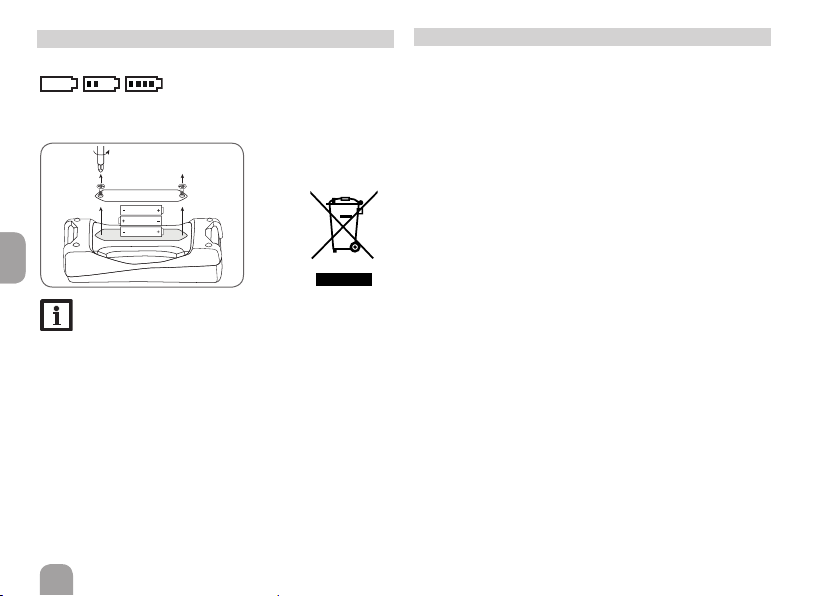
5 Batterie
Das Gerät verfügt über eine Batterieanzeige:
ÎUm die Batterien zu wechseln, folgendermaßen vor-
gehen:
Hinweis:
Batterien und Akkumulatoren enthalten giftige
Stoffe und dürfen nicht über den Hausmüll
entsorgt werden.
Wenn das Gerät länger nicht verwendet wird, die
Batterien entfernen (Auslaufgefahr).