manuals.online logo
Brands
  1. Home
  2. •
  3. Brands
  4. •
  5. Restek
  6. •
  7. Medical Equipment
  8. •
  9. Restek 27490 User manual

Restek 27490 User manual

Restek PAL SPME Manual Injection Kit
cat.# 27490
1. Description
The Restek PAL SPME manual injection kit will allow the end user to extract samples using SPME
Arrows or SPME fibers and then inject the samples into a GC inlet. The Restek PAL SPME manual
injection kit includes the components shown in Figure 1. SPME Arrows, SPME fibers, GC-specific
conversion kits (including adaptor cups), and additional adaptor cups are sold separately.
Due to the relatively large diameter of Restek PAL SPME Arrows, it will be necessary to modify
the GC inlet prior to use. Conversion kits include the following instrument-specific parts: a GC
injection port weldment, an adaptor cup, a 5-pack of liners, a 3-pack of septa, and a septum
nut. Conversion kits are available for the following types of GCs:
2. Installing a SPME Arrow or SPME Fiber in the Syringe
2.1 Loosen the cap (6) at the base of the syringe (8) and remove it (Figure 2).
2.2 Depress the black plunger completely and screw the hub of a SPME Arrow or SPME fiber
(7) into the bottom of the plunger at the end of the syringe body (8).
2.3 Slide the cap (6) over the SPME Arrow or SPME fiber and tighten it onto the syringe (8) as
shown in Figure 3.
2.4 Slide the locking screws (4 and 5) onto the syringe (8) from the plunger side (the right
side as shown in Figure 4). First, install the large ID locking screw (4) onto the silver body of the
syringe; then, install the small ID locking screw (5) onto the wider portion of the black plunger.
2.5 Tighten the locking screws until finger tight. Do not overtighten, as they will be adjusted
in subsequent steps.
Figure 1: Parts Included in the Restek PAL SPME Manual Injection Kit
1Extraction guide
2Injection guide
3Arrow/fiber syringe
4Large inner diameter (ID)
locking screw
5Small inner diameter (ID)
locking screw
Figure 2: Disassembled View of Syringe and SPME Arrow (or
Fiber) Prior to Installation
Figure 3: SPME Arrow/Fiber Installed in Syringe
Figure 4: Attaching the Locking Screws to the Syringe
1
6
2
7
4
3
8
5
5
4
GC Conversion Kit Cat.#
Thermo TRACE Ultra 27495
Thermo TRACE 1300/1310 27494
Agilent GC 6890 27492
Agilent GC 7890 27493
Shimadzu GC 2010 27491
slide the locking screws onto the
syringe from the plunger side
2 www.restek.com
3. Setting the Extraction Depth using the Extraction Guide
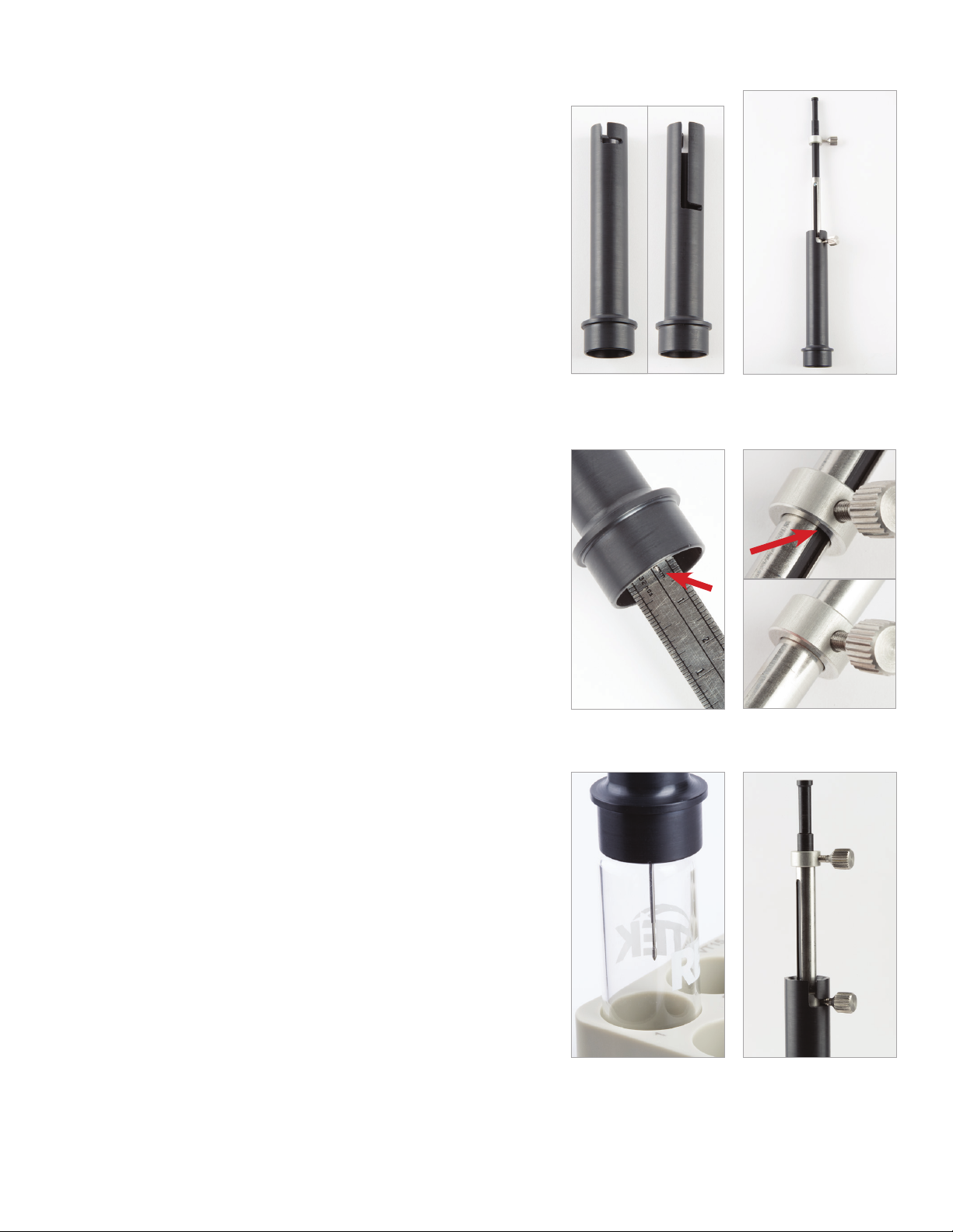
As shown in Figure 5, the extraction guide has two positions in which the syringe can be
installed. Use the upper position (9) for headspace extraction and the lower position (10) for
immersion extraction. For fine adjustment of the extraction depth, please refer to section 3.1
for headspace extraction and section 3.2 for immersion extraction. The extraction guide is de-
signed for use with 18 mm and 20 mm headspace vials.
3.1 Fine Depth Adjustment for Headspace Extraction
3.1.1 Raise the syringe plunger to the fully extended position and insert the syringe and
lower locking screw (4) into the upper position of the extraction guide. Lock the syringe
into place by rotating it until the locking screw is positioned in the notch (Figure 6).
3.1.2 Loosen the lower locking screw (4).
3.1.3 Adjust the syringe so that the SPME Arrow or SPME fiber is protruding ~1 cm beyond
the inner base of the extraction guide. When in proper position, the tip of the SPME Arrow or
SPME fiber will be recessed at least 1 mm in from the end of the extraction guide (Figure 7).
3.1.4 Tighten the lower locking screw (4) securely onto the silver body of the syringe. Do
not tighten the screw against the black plunger or you will not be able to move the SPME
Arrow or SPME fiber into position for sampling (Figure 8).
The septum penetration depth is now set. Proceed with steps 3.1.5 and 3.1.6 to the set the proper
exposure depth for headspace extraction.
3.1.5 Place the extraction guide (with the syringe in place) on an empty headspace
sampling vial and loosen the upper locking screw (5).
3.1.6 Adjust the SPME Arrow or SPME fiber to the desired exposure depth by moving the
black plunger up and down (Figure 9). Choose a depth that ensures the SPME Arrow or
SPME fiber will be in the gas phase and not submerged in the liquid phase of the sample.
3.1.7 Once the SPME Arrow or SPME fiber is at the proper depth, hold the plunger in place
and slide the upper locking screw (5) until it is flush against the top of the silver syringe
body. Then tighten the upper locking screw (5) securely as shown in Figure 10.
3.2 Fine Depth Adjustment for Immersion Extraction
3.2.1 Insert the syringe into the lower position (10) of the extraction guide (Figure 5).
3.2.2 Penetrate a vial and fully expose the SPME Arrow or SPME fiber within the vial
(Figure 11).
3.2.3 Adjust the lower locking screw (4) and upper locking screw (5) in order to obtain the
desired exposure depth (one that ensures immersion in the sample liquid). Note: If using
a SPME fiber, set a depth that prevents the tip of the fiber from hitting the bottom of the
vial as this can damage the fiber. If using a SPME Arrow, this is not a concern due to the
Arrow’s protective tip.
4. Adjusting the Injection Guide
Note: The positions of the upper (4) and lower (5) locking screws are set based on the extraction
technique and the depths used in either section 3.1 or 3.2. Do not change the position of the
locking screws during the following steps.
4.1 Carefully insert the syringe (3) into the injection guide (2). Use caution and avoid damaging
the SPME Arrow or SPME fiber when threading it through the hole in the base of the injection
guide.
4.2 Lock the syringe into place by rotating it until the locking screw is positioned in the notch
(Figure 12).
4.3 With the appropriate GC-specific adaptor cup on the end of the injection guide, measure
the distance from the tip of the SPME Arrow or SPME fiber to the groove inside the adaptor cup
(Figure 13).
4.4 Adjust the desorption depth by screwing the body of the injection guide up or down.
4.5 Set the depth to a maximum of 67 mm.
4.6 Twist the locking ring down until it locks on the body of the injection guide (Figure 14).
Figure 7: Proper Positioning
of a SPME Arrow in the
Extraction Guide
Figure 9: Exposure Depth for
Headspace Extraction
Figure 10: Upper Locking
Screw (5)
5
Figure 5: The extraction
guide has two extraction
positions (notches).
Figure 6: Syringe Installed in
the Extraction Guide
9 5
4
10
Figure 8: Incorrect and
Correction Position of the
Lower Locking Screw
3
7
www.restek.com 3
Figure 12: Injection Guide
with GC-Specific Adaptor Cup
Figure 11: Exposure Depth
for Immersion Extraction
Figure 13: Distance from Lower Groove of the Adaptor Cup to
Tip of SPME Arrow or SPME Fiber
Figure 14: Adjusting the Desorption Depth
5. Typical Workflow with Restek PAL SPME Manual Injection Kit
5.1 Extraction
5.1.1 Attach a SPME Arrow or SPME fiber to the syringe (3) and install the syringe (3) into
the extraction guide (1) at the appropriate depth settings.
5.1.2 Penetrate the sample vial septum with the black plunger up so that the SPME Arrow
or SPME fiber is fully retracted.
5.1.3 Push the black plunger down until it rests on the silver body of the syringe (3) to
expose the SPME Arrow or SPME fiber for sampling.
5.1.4 Extract for the prescribed length of time.
5.1.5 Pull the black plunger all the way up to fully retract the SPME Arrow or SPME fiber.
5.2 Remove the syringe (3) from the extraction guide (1) and place the syringe (3) into the
injection guide (2).
5.3 Injection
5.3.1 Install the syringe (3) in the injection guide (1) and set the appropriate desorption
depth using the correct GC-specific adaptor cup for your GC.
5.3.2 Penetrate the septum on the GC inlet with the black plunger up so the SPME Arrow
or SPME fiber is fully retracted.
5.3.3 Push the black plunger down until it rests on the silver body of the syringe (3),
exposing the SPME Arrow or SPME fiber in the GC inlet.
5.3.4 Desorb for the prescribed length of time.
5.3.5 Pull the black plunger all the way up to fully retract the SPME Arrow or SPME fiber.
5.3.6 Remove the injection guide and syringe from GC inlet.
Injection Guide
Body
Locking
Ring
© 2017 Restek Corporation. All rights reserved. Printed in the U.S.A.
www.restek.com
#500-60-003 Rev. date: 03/17
Restek patents and trademarks are the property of Restek Corporation. (See www.restek.com/Patents-Trademarks for full list.) Other trademarks in Restek literature
or on its website are the property of their respective owners. Restek registered trademarks are registered in the U.S. and may also be registered in other countries.

Popular Medical Equipment manuals by other brands

Otto Bock TF 1E90 Quick reference guide

Otto Bock

Otto Bock TF 1E90 Quick reference guide

HACH LANGE 8568200 manual

HACH LANGE

HACH LANGE 8568200 manual

AMO iDesign G300 Operator's manual

AMO

AMO iDesign G300 Operator's manual

Aether Biomedical Zeus Hand user guide

Aether Biomedical

Aether Biomedical Zeus Hand user guide

Orliman OP1192 INSTRUCTIONS FOR USE AND PRESERVATION

Orliman

Orliman OP1192 INSTRUCTIONS FOR USE AND PRESERVATION

Richmar ComboCare instruction manual

Richmar

Richmar ComboCare instruction manual

GE MAC 600 SPY Service manual

GE

GE MAC 600 SPY Service manual

Ohmeda GIRAFFE Operator's manual

Ohmeda

Ohmeda GIRAFFE Operator's manual

Firefly DE500 user manual

Firefly

Firefly DE500 user manual

Olympus TJF 160VR Instructions for safe use

Olympus

Olympus TJF 160VR Instructions for safe use

Sirona teneo Service manual

Sirona

Sirona teneo Service manual

Beurer FM 150 Instructions for use

Beurer

Beurer FM 150 Instructions for use

burmeier Lippe IV slatted frame instruction manual

burmeier

burmeier Lippe IV slatted frame instruction manual

idi Aspect 100RTL Q-CARD Operator's manual

idi

idi Aspect 100RTL Q-CARD Operator's manual

Otto Bock 50K90 Agilium Softfit Instructions for use

Otto Bock

Otto Bock 50K90 Agilium Softfit Instructions for use

Storz XENON NOVA 3000 instruction manual

Storz

Storz XENON NOVA 3000 instruction manual

biodex 058-840 quick start guide

biodex

biodex 058-840 quick start guide

Ergotron StyleView SV43 Tech sheet

Ergotron

Ergotron StyleView SV43 Tech sheet

manuals.online logo
manuals.online logoBrands
  • About & Mission
  • Contact us
  • Privacy Policy
  • Terms and Conditions

Copyright 2025 Manuals.Online. All Rights Reserved.