MBTelehealth Tandberg Edge 95 User manual

Tandberg Edge 95
User Guide
Prepared by:
MBTelehealth
April 2009
Updated: October 2012

MBTelehealth – Tandberg MXP Edge 95 User Guide
TABLE OF CONTENTS
1.0 OBJECTIVES ......................................................................................................................3
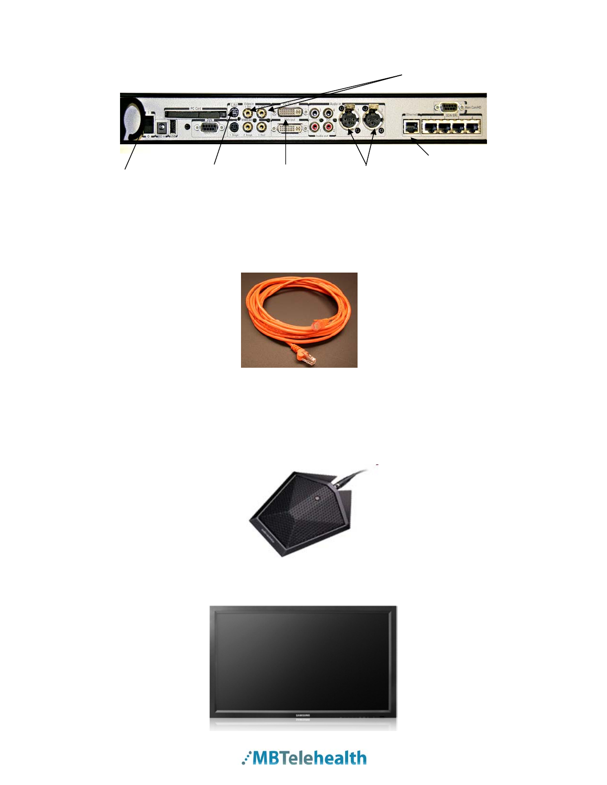
2.0 THE TANDBERG MXP EDGE 95 .......................................................................................3
3.0 GENERAL SETUP AND USE .............................................................................................6
3.1 General Setup.................................................................................................................6
3.2 Mute/Microphone.............................................................................................................7
3.3 Camera Presets ..............................................................................................................8
4.0 PLACING AND RECEIVING A VIDEO CALLS...................................................................9
4.1 Site to Site.......................................................................................................................9
4.2 Multi-Site .........................................................................................................................9
5.0 VOLUME..............................................................................................................................9
6.0 FAR END CONTROL........................................................................................................10
6.1 Site to Site.....................................................................................................................10
6.2 Multi-Site .......................................................................................................................10
7.0 PICTURE IN PICTURE .....................................................................................................11
8.0 DISCONNECTING FROM A CALL ...................................................................................11
9.0 LAPTOP/PC CONNECTION.............................................................................................12
10.0 LCD PROJECTOR ............................................................................................................13
10.1 Near End Presentation Through LCD...........................................................................13
10.2 Far End Presentation Through LCD..............................................................................14
10.3 Near End Presentation with Video Splitter....................................................................15
10.4 Near End Presentation w S-Video Out .........................................................................16
11.0 AMD PATIENT CAMERA CONNECTION.........................................................................17
11.1 Connection....................................................................................................................18
11.2 Operation.......................................................................................................................19
12.0 N_SIGHT PATIENT CAMERA ..........................................................................................20
12.1 Connection....................................................................................................................21
12.2 Operation.......................................................................................................................22
13.0 DOCUMENT CAMERA .....................................................................................................23
13.1 Connection....................................................................................................................23
13.2 Operation.......................................................................................................................24
14.0 TELESTETH- ELECTRONIC STETHESCOPE ................................................................25
15.0 GLOSSARY OF KEY TERMS...........................................................................................25
16.0 ACKNOWLEDGEMENTS..................................................................................................26
17.0 TROUBLESHOOTING ......................................................................................................26
17.1 Audio Issues..................................................................................................................26
17.2 Video Issues..................................................................................................................27
18.0 ADDITIONAL TRAINING INFORMATION ........................................................................27
APPENDIX A: TANDBERG MXP EDGE 95 QUICK REFERENCE...............................................28
APPENDIX B: VIDEOCONFERENCING ETIQUETTE..................................................................29
Page 2 of 29

Camera
MBTelehealth – Tandberg MXP Edge 95 User Guide
1.0 OBJECTIVES
This user guide will provide you with an overview of the Tandberg MXP Edge 95 and the
knowledge to setup and use the videoconferencing equipment.
Learning Outcomes:
After reviewing this guide, you should be able to:
1. Identify and explain the main parts of the Tandberg MXP Edge 95.
2. Use the remote control to navigate through the Tandberg MXP Edge 95 menus, set
camera presets, and access additional video sources.
3. Setup and use the equipment.
2.0 THE TANDBERG MXP EDGE 95
The main components of the Tandberg MXP Edge 95 videoconferencing system are the
Camera, Codec, Ethernet Cable, Microphone, Screen/Monitor, Router, Remote Control
and for some units, the Cart.
The Equipment at a Glance
Codec
1. Camera - The built-in camera is a high quality imaging device which transmits
images to the screen/monitor. The camera movements are controlled by a wireless
infra-red (IR) remote control that controls a variety of functions, both on the near and
far end.
2. Codec - The codec is the central part of the videoconferencing equipment. The main
task of the codec is the compression of outgoing video, audio and data, the
decompression of the incoming information and the transmission of this information
between endpoints. The name codec comes from a combination of the two words
compression and decompression.
Page 3 of 29

MBTelehealth – Tandberg MXP Edge 95 User Guide
The Codec (rear view) RCA Inputs/Outputs
Ethernet
On/Off Switch S-Video DVi Microphone Connection
Inputs/Outputs Inputs/Outputs Connection
3. Ethernet cable - This type of cable is similar to the one that connects to the Local
Area Network (LAN). One end is plugged into the back of the codec and the other
end (for MBTelehealth purposes), must be plugged into the specified jack in the wall.
Once the Ethernet cable is plugged in, you will be able to connect, or be connected
to other sites.
4. Microphone - There are two types of microphones that accompany the
videoconferencing equipment. The first may be located on the equipment and the
second is the table microphone which is designed to be located on a flat surface in
front of the participant. The microphone cable should always face towards the
videoconferencing system. The system will automatically equalize sound levels so
that loud and soft voices are picked up and transmitted to the far end at
approximately the same level.
5. Screen/Monitor - The videoconferencing equipment may utilize single or dual
screen/monitor configurations. The screen/monitor displays the far end or the near
end image.
Page 4 of 29

MBTelehealth – Tandberg MXP Edge 95 User Guide
6. Router -When connected to an MBTelehealth drop, the Router provides a secure
connection back to the MBTelehealth network
7. Remote Control - The remote control is used to place calls, adjust the volume,
navigate screens and select options. It controls all functions of the videoconferencing
equipment. When the remote control is not in use, it should be locked away; the
equipment will not function without it.
The Tandberg MXP Remote Control
Mic Of
f
turns your microphone
on and off.
Arrow Keys are used for
navigation in the menu and for
moving the camera
V
olume + and
–
adjusts the
s
y
stem volume.
The Layout key toggles
between full screen and
different display layouts.
Press the Call key to place a
call.
Camera Presets define specific
camera positions. Press and
hold a number key for 1 second
to save the current camera
position to that number key. To
activate a preset during a call,
simply press and release that
number key.
.
Video Sources switch between Main
Camera, Laptop, Document Camera,
DVD/VCRandAux
The Presentation key toggles
between the pc and main camera
video sources
Press Ok/Menu to show the menu
and to select menu items.
Use Zoom + and
–
to zoom the
camera in and out.
Selfview displays your outgoing
video.
Use the red End Call key to end the
current call. If you press this key and
you are not in a call, the system will
go into Standby mode.
Store and recall your video contacts
via the system Phone Book for easy
placement of calls.
Number/Letter keys function in the
same manner as with a mobile
phone.
Far End allows user to easily take
far end control during a site to site
event or change layouts in a multi-
site
Page 5 of 29

MBTelehealth – Tandberg MXP Edge 95 User Guide
NAVIGATION BUTTONS
ARROW KEYS, OK AND MENU BUTTON
To navigate through the menu in the videoconferencing system,
use the arrow keys. To make a selection when in a menu, press
the OK/Menu button. An orange selector on screen shows the
selected item. To bring up the menu, press the OK/Menu button.
CANCEL KEY
In the main menu, pressing Cancel (X) will hide the menu. If the
menu is hidden, you can access it again by pressing the OK
button. In other menus, pressing Cancel (X) will take you back one
step. In an input field, pressing Cancel (X) will delete
characters/numbers to the left.
8. Cart – The cart makes the video conference system ‘mobile’ and allows it to be
utilized in multiple locations and different types of events within a facility. One
system can serve multiple purposes. Note: carts are not included in all solutions.
3.0 GENERAL SETUP AND USE
The following sections will provide instructions for setting up and using your Tandberg
MXP Edge 95 to place and receive video conference calls. A Quick Reference guide is
available in Appendix A to review how to set up and use your video conference system.
3.1 General Setup
To setup and use the Tandberg Edge 95 video conference equipment:
Page 6 of 29

MBTelehealth – Tandberg MXP Edge 95 User Guide
1. Position the equipment in the specified location/room
2. Plug the power cord into the wall.
3. Connect the free end of the Ethernet cable to the MBTelehealth jack
4. Turn on the codec, the screen/monitor and the router. After approximately 15-20
seconds you will see the startup screen. . (If the Ethernet cable is connected
correctly, you will see a flashing green VPN light on the front of the Cisco router.)
5. Place the microphone on the table in front of the participants. If possible, position
the microphone at least 6.5 feet in front of the system
6. Press Cancel once then position the camera on the participant(s) using the arrow
keys and the zoom + and - keys.
For more information on setting and storing camera positions see section 3.3
Camera Presets The Startup Screen
3.2 Mute/Microphone
To mute the microphone:
1. Press the Mic Off key on the remote control.
2. An onscreen indicator will appear when the microphone is off.
3. Press the Mic Off key on the remote control again to turn the mute off. The
onscreen indicator will disappear from the screen.
Make sure your site is on mute before making a call to the far end. Turn
the mute off when you are ready to begin the session.
Page 7 of 29

MBTelehealth – Tandberg MXP Edge 95 User Guide
3.3 Camera Presets
Camera presets are useful when pictures from many different camera positions and
video sources have to be viewed by the far end. Presets are used to switch camera
positions without having to manually move the camera every time.
Presets can be established before or during a call.
The camera presets are available from the number keys on the remote control when in a
call or by using the preset button when not in a call.
3.3.1 Standardized Presets
MBTelehealth recommends setting the following setting the following camera presets for
each video conference event:
1. Sign - The first preset is of a sign with the sites name. This is an off screen
camera view that allows users to move about the room without being on camera
and identifies the sites that are connected. The equipment should always be set
to the sign preset before connecting to an event.
2. Participant (Presenter/Provider/Patient) – This preset is a close up view of the
person or persons involved in the event. Whether it is the patient, provider or a
presenter, when setting this preset, you want to ensure that the far sites are able
see the person clearly.
3. Room –Part of video conference etiquette includes making the sites you are
connected to aware of everyone involved in the event. By setting a preset of the
entire room, you can easily identify everyone in attendance and then switch back
to preset number 2 as necessary. This preset is also helpful for question and
answer periods.
Setting these presets provides consistency for users and service desk staff for all
telehealth equipment.
3.3.2 Saving Camera Presets
To save a preset from the remote control:
1. Move the camera to the desired position. If storing a video source ensure it is
selected and showing on screen.
2. Press a number key on the remote control (from 0-9) until a message appears
stating the preset has been stored. The new preset will overwrite any existing
camera presets on that number.
3.3.3 Using Camera Presets
To use camera presets:
1. Press the Presets button on the remote control. A message will appear
on the screen saying Presets 0-9
2. Press the number on the remote control that corresponds with the desired
camera position, or video source.
Page 8 of 29

MBTelehealth – Tandberg MXP Edge 95 User Guide
4.0 PLACING AND RECEIVING A VIDEO CALLS
4.1 Site to Site
To place a video call:
1. Press the Phone Book key on the remote control.
2. Scroll down the list of contacts. Once you have found the site you want to
connect to, press the OK button on the remote control.
You can quickly skip to the site you are looking for using the corresponding
number key on the remote control. For example, if you are looking for Pine Falls,
press #7 on the remote to skip to the P section of the phone book.
3. Press the OK button once more on the remote control to initiate the call.
4.2 Multi-Site
For sessions with 3 or more participating sites, you will be automatically dialed in by the
MBTelehealth service desk. If you are participating in a multi-site session, have your
equipment set up and turned on at least 15 minutes prior to the scheduled start time with
the microphone on mute. Do not attempt to connect to the other location.
5.0 VOLUME
To adjust the volume:
1. Press the Volume + or – key on the remote control to adjust the volume. The
volume indicator appears on the top left corner of the screen.
Remote Control Volume Indicator
When the volume is turned off, the volume indicator2. will appear onscreen.
Press the Volume + key to remove the indicator.
During a conference, all sites should be muted with the exception of the
presenter’s site. If the participants at the far end are having trouble hearing you,
Page 9 of 29

MBTelehealth – Tandberg MXP Edge 95 User Guide
they may need to adjust their volume or you may need to adjust yours. Make
sure that the volume on the monitor is on. It should be adjusted to the halfway
point as shown below.
Screen/Monitor Volume Indicator
6.0 FAR END CONTROL
6.1 Site to Site
Taking Far End Camera Control allows you to move the camera at the far end site as
well as control their video sources and presets during Site to Site calls only. However,
you cannot save far end camera presets.
Before taking far end camera control, always request permission first and explain why
you are taking control. You may need to take far end camera control if:
There is an unskilled operator at the far end.
The operator requests that you take control.
If the operator isn’t able to facilitate the event at their end.
To use far end camera control during a call:
1. Press the Far End button on the remote control.
2. Move the camera to the desired position using the directional arrows on the
remote control. Zoom in and out on the person or item you want to see.
3. Press the Far End button again to turn far end control off
6.2 Multi-Site
During Multi-Site calls, the Far End button allows you to control how the other sites are
displayed on your screen.
To split the screen in a multipoint session:
1. Press the Far End button on the remote control then toggle through the
layout options using the up arrow.
2. Press the Far End button again to turn far end control off
Layout Options
Page 10 of 29

MBTelehealth – Tandberg MXP Edge 95 User Guide
7.0 PICTURE IN PICTURE
The layout button on the remote control makes it possible to see a secondary image in a
small window in one corner of the screen (Picture in Picture [PIP]). The user can decide
in which corner the second image is to be displayed.
Example of PIP
To use Picture in Picture (PIP):
1. Press the Layout key once on the remote control to bring up a PIP.
2. Press the Layout key again to move the PIP around in the corners of the screen
and to finally hide it.
3. Press and hold the Layout key for 1 second to hide the small picture directly from
any position.
4. To switch the PIP to a larger view on a single monitor, press the Selfview button.
To remove the larger view, press the Selfview button again.
8.0 DISCONNECTING FROM A CALL
To disconnect from a call:
1. Mute the microphone by pressing Mic Off.
2. Press the red End Call Key twice on the remote control to disconnect a
call.
End Call Dialogue Box
Page 11 of 29

3.
MBTelehealth – Tandberg MXP Edge 95 User Guide
Place the remote control in a safe area.
It takes a few moments for the audio to turn off when disconnecting from a
call. Therefore, it is important to mute the microphone when the session is
over.
9.0 LAPTOP/PC CONNECTION
To connect a laptop to the videoconferencing equipment:
1. Using a VGA/ DVI cable, connect the DVI end to the DVI-I In at the back of the
codec. DVI Connector
Rear View of the Codec
PC/DVI-I In
2. Connect the VGA end to the matching port on the laptop.
VGA Connector
3. Turn the laptop on.
4. Press the Presentation button on the remote control.
5. You should now see you PC displayed on the video conference monitor.
If not, do the following: on the laptop keyboard, press the Function key (Fn) and
the appropriate F key (often F5, F8 or F10) simultaneously. A display options
menu will appear, select the option to display on both as shown below.
Page 12 of 29

MBTelehealth – Tandberg MXP Edge 95 User Guide
Display options
6. Press the Presentation button again to return to the Main Camera view.
7. To disconnect, remove the VGA cable from the laptop.
10.0 LCD PROJECTOR
There are multiple options for connecting LCD projectors to display presentations using
videoconference equipment. The following text identifies the four most common
configurations used on the MBT network.
10.1 Near End Presentation Through LCD
This connection method allows the pc image to be displayed through the LCD Projector
without going through the codec first, thus allowing for a higher quality image displayed
at the near site. For this connection to work, the LCD Projector must have video output
capabilities. Use this connection if you do not have a video splitter available.
To connect the laptop to the video conference equipment through the LCD
projector:
1. Using a VGA cable, connect one end to the laptop and the other end to a VGA
input on the LCD Projector; then turn the laptop on.
2. You should now see the laptop image on the projector screen.
If the image does not display press the input button on the LCD to search for the
input or use the appropriate function key on your laptop (often F5, F8, or F10) to
send out the image.
3. Using a VGA/DVI cable, connect the VGA end to video output on the LCD
projector and then connect the DVI end to the PC DVI In on the back of the
codec
4. Press the Presentation button on the remote control to display the
PC image to the far site
5. Press the Presentation button again to return to your main camera image
Page 13 of 29

MBTelehealth – Tandberg MXP Edge 95 User Guide
10.1.1 Diagram
Codec
DVI In
VGA Out
LCD Projector
VGA In
Laptop
10.2 Far End Presentation Through LCD
This set up will allow you to display a presentation from a far end site through an LCD
projector onto a larger screen for easier viewing by the audience at your site.
To display a far end presentation on the LCD Projector:
1. Using an S-Video cable, connect one end to S-Video Out on the back of the
codec then connect the other end to a S-Video input on the LCD projector
2. You should now see the codec image through the LCD Projector.
Page 14 of 29

10.2.1 Diagram
MBTelehealth – Tandberg MXP Edge 95 User Guide
Codec
S-Video Out
S-Video In
LCD Pro
j
ecto
r
10.3 Near End Presentation with Video Splitter
This method of connection allows you to display the near end presentation through the
video conference equipment and the LCD Projector simultaneously. Connecting through
a video splitter is the easiest way to display a high quality image through both the LCD
Projector and share it with the far end site.
To display the near end presentation on the LCD Projector with a video splitter:
1. Using a VGA cable, connect one end to VGA Input on the Video Splitter, then
connect the other end to the matching port on the laptop and turn the laptop on
2. Using a second VGA Cable, connect one end to the VGA Input on the LCD
Projector and the other end to one of the VGA Outputs on the Video Splitter.
3. You should now see the laptop image on the projector screen.
If the image does not display press the input button on the LCD to search for the PC
input or use the appropriate function key on your laptop (often F5, F8, or F10) to
send out the image.
4. Using a VGA /DVI Cable, connect the DVI end to the PC DVI- In on the back of
the codec and the other end to the remaining VGA Output on the Video Splitter.
5. Press the Presentation button on the remote control to display the
PC image to the far site
6. Press the Presentation button again to return to your main camera image
Page 15 of 29

MBTelehealth – Tandberg MXP Edge 95 User Guide
10.3.1 Diagram
Video Splitter
LCD Pro
j
ecto
r
Codec
VGA In DVI In
VGA In
VGA Out VGA Out
VGA Out
La
p
to
p
10.4 Near End Presentation w S-Video Out
This method of connection allows you to display the near end presentation through the
video conference equipment and the LCD Projector simultaneously. Use this set up if a
video splitter is not available and the LCD projector does not have video output
capabilities.
To display the near end presentation using S-Video out on the codec:
1. Using a VGA/DVI cable, connect the DVI end to PC DVI In on the back of the
codec then connect the VGA end to the matching port on the laptop and turn the
laptop on
2. Using an S-Video cable, connect one end to S-Video Out on the back of the
codec then connect the other end to a S-Video input on the LCD projector.
3. Press the Presentation button on the remote control to display the
PC image to the far site
Page 16 of 29

MBTelehealth – Tandberg MXP Edge 95 User Guide
4. Press the Presentation button again to return to your main camera image
If the image does not display and/or you get a “pc not connected” message on your
video conference equipment, use the appropriate function key on your laptop (often
F5, F8, or F10) to send out the image.
5. You should now see the codec image through the LCD Projector. Once
connected, you will need to press the Selfview button to swap images so the
near end presentation shows through the projector.
6. Press the Selfview button again to return to the previous view
10.4.1 Diagram
Codec
S-Video Out DVI In
VGA Out
S-Video In
La
p
to
p
LCD Pro
j
ecto
r
* Some VC carts will have a dongle attached that will allow the user to output to an LCD
projector using a VGA cable instead of an S-Video cable.
11.0 AMD PATIENT CAMERA CONNECTION
The AMD General Examination Camera is used to examine objects in fine detail. This
hand-held camera is compact and lightweight, with all the controls located on the
camera itself. It is multi-purpose as it can be used for many telehealth applications
including dermatology, seating assessments and gate reviews. The camera can also be
used to examine various areas of the body unobtrusively.
Page 17 of 29

MBTelehealth – Tandberg MXP Edge 95 User Guide
Patient Camera
11.1 Connection
To connect the patient camera to the Tandberg MXP Edge 95:
1. Plug the DC/VBS cable to the back of the patient camera. Make sure the cable is
secure.
1 Power Indicator
2 Power Switch
3 Light Switch
4 White Balance Button
5 Focus Switch
6 Far
7 Near
8 Manual Iris Indicator
9 Iris Button
10 Manual Iris Dial
11 Y/C Port
12 LDC/VBS Port
13 Serial Number
2. Plug in the other end of the DC/VBS cable and the power adaptor cord into the
AMD junction box as shown below:
3. Connect one end of the S-Video cable to the AUX Input at the back of the codec.
Page 18 of 29

MBTelehealth – Tandberg MXP Edge 95 User Guide
4. Plug the other end of the S-Video cable into the Y/C Input at the back of the
patient camera.
5. Plug the power adapter cord into an outlet.
6. Move the Power Switch to ON, move the Light Switch to ON and verify that the
7. Press the AUX button on the Tandberg remote control to display the
8. Press the Main Cam button to return to the previous view.
It is recommended that while using the patient camera, you view the near end image
on your main screen. This will make it easier for you to see what you are doing.
To swap your main camera display:
green power indicator light is ON.
Patient Camera image to the far site.
1. Press the Selfview button on your remote control.
2. Press the Selfview button again to return to the previous view.
The patient camera should be inspected for proper operation on a
regular basis. It should also be cleaned and disinfected with a damp cloth
after each patient contact.
11.2 Operation
To operate the patient camera:
1. Turn on the patient camera and perform a white balance
Turn on the light, using the switch on the back of the camera.
Place a white sheet of paper in front of the camera. Fill the screen
completely with the image of the white sheet.
Press the WB button and release it. Continue to point the camera at the
white sheet of paper for three seconds. You should be able to see a
change in color. The colors will now be automatically rebalanced.
2. Point the patient camera at the subject or image.
3. Use the image control buttons on top of the patient camera to zoom in and out
and focus on the object.
Page 19 of 29

MBTelehealth – Tandberg MXP Edge 95 User Guide
Top View of Patient Camera
4. Use the FRE button if the image is shaky and you want to capture a still image.
5. Use the REF button to adjust the remove glare or reflection on the object
6. Once completed, turn the Power and the Light OFF.
12.0 N_SIGHT PATIENT CAMERA
The patient camera is used to examine objects in fine detail. This hand-held camera is
compact and lightweight, with all the controls located on the camera itself. It is multi-
purpose as it can be used for many telehealth applications including dermatology,
seating assessments and gait assessments. The camera can also be used to examine
various areas of the body unobtrusively.
Parts of the n_sight Patient Camera
2
1
3
4
5 6 7
8
10
9
1 Still Image Capture 6 Viewfinder
2 LED Display 7 Zoom in/out
3 Onboard Light 8 Light on/off
4 S-Video Port 9 Power button
5 Stylus 10 External Power Connector
Page 20 of 29
Other manuals for Tandberg Edge 95
1
Table of contents
Other MBTelehealth Conference System manuals