Instruction Manual Page 2
Thank you for purchasing the Retracta R3 retractable hose reel.
PLEASE READ THIS SAFETY INFORMATION CAREFULLY BEFORE USE.
Read and retain this instruction manual to assist you in the operation of your new product.
‘CAUTIONS’ are listed throughout this manual to advise of actions that may cause damage to you’re
the operator or to the equipment.
The following general warnings should be observed when installing, operating or maintaining hose reel equip-
ment. Further specific warnings pertaining to specific dangers may be found within this document
CAUTION
* Do not exceed the maximum working pressure for
this reel. (Refer to the product specifications)
* Only use compatible fluids with this reel.
(Refer to compatible fluids in product specifications)
* Check equipment daily for wear or damage.
(Replace worn or damaged items immediately with
genuine replacement parts).
* Use equipment for intended use only.
* Check equipment daily for leaks.
(Repair or replace as required)
* Do not alter or modify equipment.
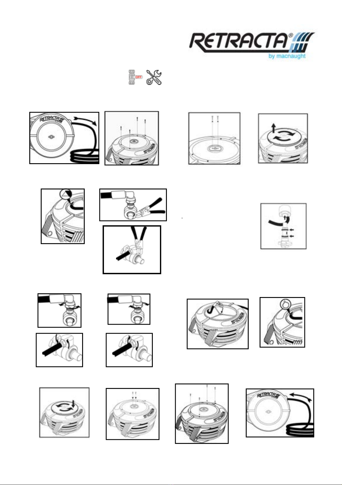
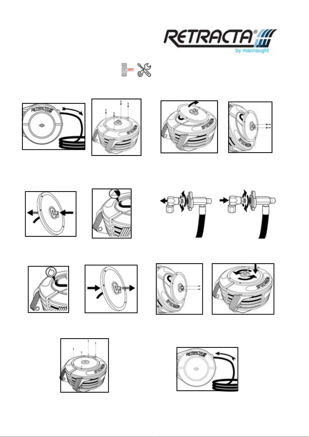
Before attempting any maintenance
disconnect and turn off supply line,
then release the line pressure.
* Do not let go of the hose when rewinding.
* Use reel in well ventilated areas if toxic or flammable
fluids are in use
* Do not attempt to stop leaks with your hand or body.
Note,
This is not an exhaustive list of hazards and warnings. All care should be taken to maintain safe working proce-
dures when installing, operating and maintaining the equipment. It is recommended that only trained professional
trades people with the appropriate working knowledge of such equipment be charged with its installation and
maintenance.
INTRODUCTION
* Operator should wear appropriate protection
equipment to protect against personal injury .
* Caution should be observed against burning due to
hot water teperature when using hot water reels.