manuals.online logo
Brands
  1. Home
  2. •
  3. Brands
  4. •
  5. Rev-A-Shelf
  6. •
  7. Indoor Furnishing
  8. •
  9. Rev-A-Shelf Elite 53PSPE Series User manual

Rev-A-Shelf Elite 53PSPE Series User manual

This manual suits for next models

10

Other Rev-A-Shelf Indoor Furnishing manuals
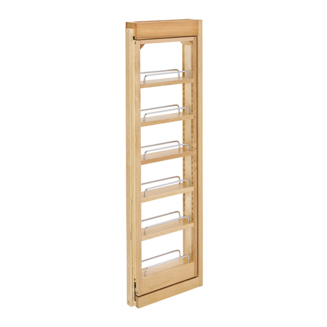
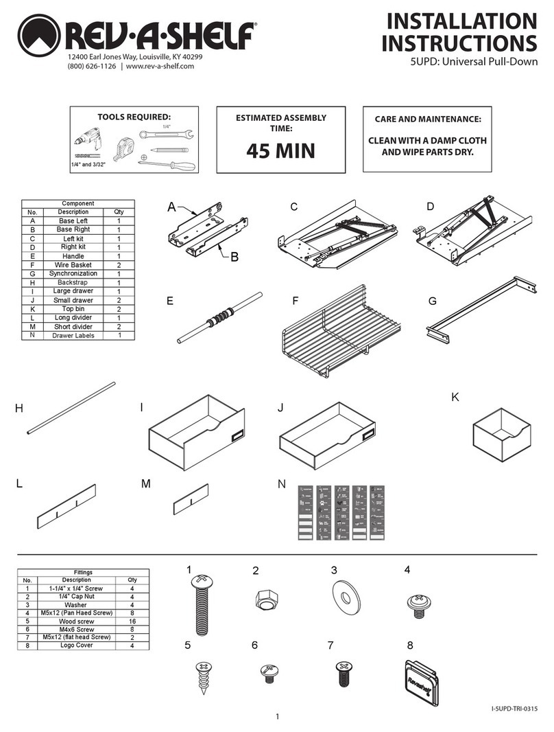
Rev-A-Shelf Wood Classics 432 Series User manual
Rev-A-Shelf

Rev-A-Shelf Wood Classics 432 Series User manual

Rev-A-Shelf 5UPD User manual

Rev-A-Shelf

Rev-A-Shelf 5UPD User manual
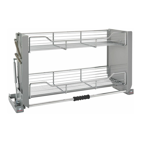
Rev-A-Shelf 5PD Series User manual

Rev-A-Shelf

Rev-A-Shelf 5PD Series User manual
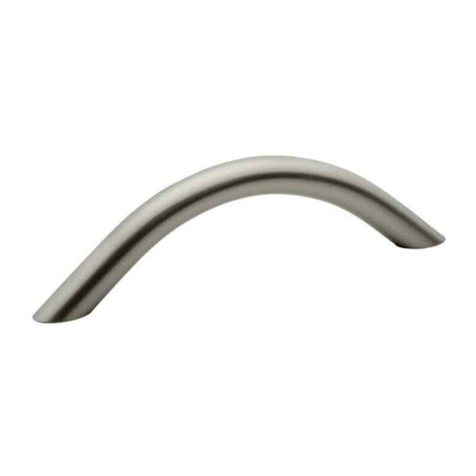
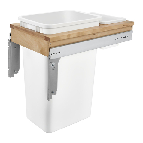
Rev-A-Shelf CHDSL-996-SN-1 User manual
Rev-A-Shelf

Rev-A-Shelf CHDSL-996-SN-1 User manual

Rev-A-Shelf 1550DM1-343-FL User manual
Rev-A-Shelf

Rev-A-Shelf 1550DM1-343-FL User manual

Rev-A-Shelf JEWELRY DRAWER User manual
Rev-A-Shelf

Rev-A-Shelf JEWELRY DRAWER User manual

Rev-A-Shelf CVRI Series User manual

Rev-A-Shelf

Rev-A-Shelf CVRI Series User manual
Rev-A-Shelf 448 User manual

Rev-A-Shelf

Rev-A-Shelf 448 User manual
Rev-A-Shelf 5WB-DMKIT User manual

Rev-A-Shelf

Rev-A-Shelf 5WB-DMKIT User manual

Rev-A-Shelf GRP21891 User manual

Rev-A-Shelf

Rev-A-Shelf GRP21891 User manual
Rev-A-Shelf 548-10 User manual

Rev-A-Shelf

Rev-A-Shelf 548-10 User manual
Rev-A-Shelf 5707 User manual

Rev-A-Shelf

Rev-A-Shelf 5707 User manual
Rev-A-Shelf WOVEN BASKET User manual

Rev-A-Shelf

Rev-A-Shelf WOVEN BASKET User manual
Rev-A-Shelf WLS Series User manual

Rev-A-Shelf

Rev-A-Shelf WLS Series User manual
Rev-A-Shelf 4PIL-18SC-2 User manual

Rev-A-Shelf

Rev-A-Shelf 4PIL-18SC-2 User manual
Rev-A-Shelf 5CCSO Series User manual

Rev-A-Shelf

Rev-A-Shelf 5CCSO Series User manual
Rev-A-Shelf TWO-TIER FILE DRAWER SYSTEM User manual
Rev-A-Shelf

Rev-A-Shelf TWO-TIER FILE DRAWER SYSTEM User manual

Rev-A-Shelf 5322BCSC11GR User manual

Rev-A-Shelf

Rev-A-Shelf 5322BCSC11GR User manual
Rev-A-Shelf Wood Classics 444 Series User manual
Rev-A-Shelf

Rev-A-Shelf Wood Classics 444 Series User manual

Rev-A-Shelf 448TP User manual

Rev-A-Shelf

Rev-A-Shelf 448TP User manual

Rev-A-Shelf R.4WV.15WN User manual

Rev-A-Shelf

Rev-A-Shelf R.4WV.15WN User manual

Rev-A-Shelf 9" Two-Tier Basket User manual

Rev-A-Shelf

Rev-A-Shelf 9" Two-Tier Basket User manual

Rev-A-Shelf 5786-900-CW-1 User manual

Rev-A-Shelf

Rev-A-Shelf 5786-900-CW-1 User manual

Rev-A-Shelf 445VBOSC8C User manual

Rev-A-Shelf

Rev-A-Shelf 445VBOSC8C User manual

Popular Indoor Furnishing manuals by other brands

Regency LWMS3015 Assembly instructions

Regency

Regency LWMS3015 Assembly instructions

Furniture of America CM7751C Assembly instructions

Furniture of America

Furniture of America CM7751C Assembly instructions

Safavieh Furniture Estella CNS5731 manual

Safavieh Furniture

Safavieh Furniture Estella CNS5731 manual

PLACES OF STYLE Ovalfuss Assembly instruction

PLACES OF STYLE

PLACES OF STYLE Ovalfuss Assembly instruction

Trasman 1138 Bo1 Assembly manual

Trasman

Trasman 1138 Bo1 Assembly manual

Costway JV10856 manual

Costway

Costway JV10856 manual
moss DESIGN Caisson Credenza Assembly instructions

moss DESIGN

moss DESIGN Caisson Credenza Assembly instructions

Aquaglide FULL DECK 15.0 owner's manual

Aquaglide

Aquaglide FULL DECK 15.0 owner's manual

AREBOS AR-HE-SW30 user manual

AREBOS

AREBOS AR-HE-SW30 user manual

Till-Hilft Fulda 87005.330 Assembly instructions

Till-Hilft

Till-Hilft Fulda 87005.330 Assembly instructions

Twoey Outside 2010 quick start guide

Twoey Outside

Twoey Outside 2010 quick start guide

Hettich Easys 200 operating instructions

Hettich

Hettich Easys 200 operating instructions

The bedboss RELAX 404 Series owner's manual

The bedboss

The bedboss RELAX 404 Series owner's manual

Oeseder Möbelindustrie Bern 991 720 Assembly instructions

Oeseder Möbelindustrie

Oeseder Möbelindustrie Bern 991 720 Assembly instructions

Costway HW68469 user manual

Costway

Costway HW68469 user manual

Next ALIX A27743 Assembly instructions

Next

Next ALIX A27743 Assembly instructions

BROSA Hans Assembly guide

BROSA

BROSA Hans Assembly guide

Prodigg MINIKA PBA015T-FUR installation manual

Prodigg

Prodigg MINIKA PBA015T-FUR installation manual

manuals.online logo
manuals.online logoBrands
  • About & Mission
  • Contact us
  • Privacy Policy
  • Terms and Conditions

Copyright 2025 Manuals.Online. All Rights Reserved.

I-53PSPE-0723
WATCH VIDEO TUTORIALS OF PRODUCT INSTALLATIONS
WWW.REV-A-SHELF.COM/VIDEOS
12400 Earl Jones Way
Louisville, KY 40299
rev-a-shelf.com
800-626-1126
53PSPE SOFT-CLOSE ELITE BLIND CORNER OPTIMIZER
TOOLS REQUIRED:
45 MIN
ESTIMATED ASSEMBLY TIME:
CARE AND MAINTENANCE:
Clean with a damp cloth and
wipe parts dry.
INSTALLATION OPTIONS
Blind Right/Left Door
Application ............ page 2
Blind Left/Right Door
Application ............ page 6
#2
#2
1
16
F
G
H
I
J
K
L
M
N
O
P
UNIT PARTS LIST:
Item # Description QTY
A Base 1
B Frame 1
C Feet 2
D Guide Channel 1
E Solid Bottom Trays 4 or 6
Three-Tier (53PSPE3-XX)
HARDWARE PARTS LIST:
Item # Description QTY
FHandles L/R 2
GM6 x 10 mm Wafer Head Screws 8
HM5 x 6 mm Flat-Head Screws 8
I5/32 x 18 mm Wood Screws 19
JShoulder Bolts 2
KTop Wheels 2
LArms 2 or 4
MShelf Retainers 4 or 8
NM4 Countersunk Flat-Head Screws 4
OM5 Phillips Round Washer Head Screws 4 or 8
PM4 Truss Head Phillips/Slotted Screws 4 or 8
Item No. 5PSP-15
A
B
C
D
E
5
4
3
1
2
1
1
4
1
2
19
2
20141120-B01
8
8
1/2
A
B
C
D
E
1
1
2
3
4
5
1
2
B
3
5
D
4
A
4
E
1.
2. 3.
4. 5.
(Left)
QTY
Description
Description
PANELS CHECK LIST
FITTINGS CHECK LIST
Base
Frame
Foot
M4x10mm flat-headed screw
Handle
5/32 x18mm wood screw
QTY
M6x10mm wafer head screw
Guide channel
Basket
M5x6mm flat-headed screw
12” (305mm)
7-1/4 ”
(184mm)
10” (256mm)
C
D
1
2
3
4
5
6
7
8
9
10
11
B
5PSP-XXSC-CR
for a door drawer application
A
C
D
For 15” (380 mm) unit
For 18” (450 mm) unit
E
5PSP3-XXSC-CR
for a full height application
(Not available in Orion Gray)
Two-Tier (53PSPE-XX)
E
AB
C
DE
800-626-1126 | rev-a-shelf.com
2
Conrm the size of your
cabinet and measure to nd
your rst base hole location.
STEP 1
Door Drawer Blind RightDoor Drawer Blind Right
Full Height Blind RightFull Height Blind Right
Blind Portion
of Cabinet
Door Opening
Door Opening
Door Opening
Door Opening
Shown with adjacent cabinet
Blind Portion
of Cabinet
Door Drawer Blind LeftDoor Drawer Blind Left
Full Height Blind LeftFull Height Blind Left
Blind Portion
of Cabinet
Door Opening
Door Opening
Door Opening
Door Opening
Shown with adjacent cabinet
Blind Portion
of Cabinet
Blind Portion
of Cabinet
Door Opening
53PSPE (BLIND RIGHT/LEFT DOOR)
Align the Base (A) over the
marked base hole location
from Step 1 and pre-drill the
(10) mounting holes using a
1-16” drill bit ensuring the
frame is straight in cabinet.
Note: “Blind” sticker on the
Base (A) should be in the blind
of the cabinet.
STEP 2
STEP 3
Secure Base (A) to the cabinet
oor with (10) 5/32 x 18 mm
Wood Screws (I).
Note: (8) additional screws
(included) can be added for
stability.
#2
#2
1
16
#2
#2
1
16
#2
#2
1
16
#2
#2
1
16
or
#2
#2
1
16
#2
#2
1
16
Item No. 5PSP-15
A
B
C
D
E
5
4
3
1
2
1
1
4
1
2
19
2
20141120-B01
8
8
1/2
A
B
C
D
E
1
1
2
3
4
5
1
2
B
3
5
D
4
A
4
E
1.
2. 3.
4. 5.
(Left)
QTY
Description
Description
PANELS CHECK LIST
FITTINGS CHECK LIST
Base
Frame
Foot
M4x10mm flat-headed screw
Handle
5/32 x18mm wood screw
QTY
M6x10mm wafer head screw
Guide channel
Basket
M5x6mm flat-headed screw
12” (305mm)
7-1/4 ”
(184mm)
10” (256mm)
x1
A
x10
F
G
H
I
J
K
L
M
N
O
P
BLIND
Face Frame From Front of Cabinet
FIRST BASE
HOLE
From Door Opening
(368mm)
14-1/2"
7-1/4"
(184mm)
BLIND
From Front of CabinetFace Frame
FIRST BASE
HOLE
From Door Opening
(318mm)
12-1/2"
7-1/4"
(184mm)
BASE HOLE
LOCATION BLIND
BASE HOLE
LOCATION BLIND
Fig B)
Fig C)
Fig A)
53PSPE-15 53PSPE-18
3
Pre-start (2) M5 x 6 mm Flat-
Head Screws (H) into the front
of the Base (A) and hook the
rear of the Guide Channel (D)
onto the screws. Once in place,
tighten M5 x 6 mm Flat-Head
Screws (H)
STEP 4
Attach the Handles (F) to
the Frame (B) with (2) M4
Countersunk Flat-Head Screws
(N) each.
STEP 5
Attach Top Wheel (K) using
Shoulder Bolt (J) directly in
front of each Handle (F).
STEP 6
#2
#2
1
16
#2
#2
1
16
#2
#2
1
16
D
x1
1
2
3
4
5
6
7
8
9
10
11
B
5PSP-XXSC-CR
for a door drawer application
A
C
D
For 15” (380 mm) unit
For 18” (450 mm) unit
E
5PSP3-XXSC-CR
for a full height application
(Not available in Orion Gray)
x1
B
D
x2
F
G
H
I
J
K
L
M
N
O
P
F
G
H
I
J
K
L
M
N
O
P
F
G
H
I
J
K
L
M
N
O
P
x4
F
G
H
I
J
K
L
M
N
O
P
F
G
H
I
J
K
L
M
N
O
P
x2
x2
F
G
H
I
J
K
L
M
N
O
P
F
G
H
I
J
K
L
M
N
O
P
x2
F
G
H
I
J
K
L
M
N
O
P
F
G
H
I
J
K
L
M
N
O
P
Fig D)
Fig E)
Fig F)
800-626-1126 | rev-a-shelf.com
4
Attach the Arms (L) with (2) M5
Phillips Round Washer Head
Screws (O) each.
Note: (2) Arms included with the
two-tier unit and (4) Arms are
included with the three-tier unit.
Note: Support arms can be
adjusted up or down to level
the supported shelf.
STEP 7
Flip Frame (B) on its back and
move pre-installed left wheel to
the top position as shown (Fig I)
for a Blind Right/Left Door.
STEP 8
Orient the arrows on the Feet
(C) and Frame (B) in the same
direction and secure using
(8) M6 x 10 mm Wafer Head
Screws (G).
STEP 9
#2
#2
1
16
#2
#2
1
16
#2
#2
1
16
x2 (or 4)
x4 (or 8)
C
x2
x8
C
F
G
H
I
J
K
L
M
N
O
P
F
G
H
I
J
K
L
M
N
O
P
F
G
H
I
J
K
L
M
N
O
P
Fig G)
Fig H)
Fig J)
Fig I)
Fig K)
5
Set Frame (B) on top of Base
(A) inside of the cabinet and
secure the Feet (C) to the Base
(A) using (6) M5 x 6 mm Flat-
Head Screws (H).
STEP 10
STEP 11
#2
#2
1
16
or
#2
#2
1
16
#2
#2
1
16
#2
#2
1
16
or
#2
#2
1
16
#2
#2
1
16
x6
E
x4 (or 6)
x4 (or 8)
x4 (or 8)
F
G
H
I
J
K
L
M
N
O
P
F
G
H
I
J
K
L
M
N
O
P
F
G
H
I
J
K
L
M
N
O
P
Attach Solid Bottom Trays (E)
by securing on hooks directly
behind the rst wire, see
illustration.
Secure top (and middle tier if
applicable) Solid Bottom Trays
(E) to the Frame (B) with (2)
Shelf Retainers (M) and (2) M4
Truss Head Phillips/Slotted
Screws (P).
Fig L)
Fig M)
800-626-1126 | rev-a-shelf.com
6
Conrm the size of your
cabinet and measure to nd
your rst base hole location.
STEP 1
Door Drawer Blind RightDoor Drawer Blind Right
Full Height Blind RightFull Height Blind Right
Blind Portion
of Cabinet
Door Opening
Door Opening
Door Opening
Door Opening
Shown with adjacent cabinet
Blind Portion
of Cabinet
Door Drawer Blind LeftDoor Drawer Blind Left
Full Height Blind Left
Blind Portion
of Cabinet
Door Opening
Door Opening
Door Opening
Door Opening
Shown with adjacent cabinet
Blind Portion
of Cabinet
Blind Portion
of Cabinet
Door Opening
53PSPE (BLIND LEFT/RIGHT DOOR)
Align the Base (A) over the
marked base hole location
from Step 1 and pre-drill the
(10) mounting holes using a
1-16” drill bit ensuring the
frame is straight in cabinet.
Note: “Blind” sticker on the
Base (A) should be in the blind
of the cabinet.
STEP 2
STEP 3
Secure Base (A) to the cabinet
oor with (10) 5/32 x 18 mm
Wood Screws (I).
Note: (8) additional screws
(included) can be added for
stability.
#2
#2
1
16
#2
#2
1
16
#2
#2
1
16
or
#2
#2
1
16
#2
#2
1
16
Item No. 5PSP-15
A
B
C
D
E
5
4
3
1
2
1
1
4
1
2
19
2
20141120-B01
8
8
1/2
A
B
C
D
E
1
1
2
3
4
5
1
2
B
3
5
D
4
A
4
E
1.
2. 3.
4. 5.
(Left)
QTY
Description
Description
PANELS CHECK LIST
FITTINGS CHECK LIST
Base
Frame
Foot
M4x10mm flat-headed screw
Handle
5/32 x18mm wood screw
QTY
M6x10mm wafer head screw
Guide channel
Basket
M5x6mm flat-headed screw
12” (305mm)
7-1/4 ”
(184mm)
10” (256mm)
x1
A
x10
F
G
H
I
J
K
L
M
N
O
P
From Door Opening
Face Frame
From Front of Cabinet
FIRST BASE
HOLE
14-1/2"
(368mm)
7-1/4"
(184mm)
BLIND
BLIND BASE HOLE
LOCATION
BLIND BASE HOLE
LOCATION
From Front of Cabinet Face Frame
From Door Opening
FIRST BASE
HOLE
12-1/2"
(318mm)
7-1/4"
(184mm)
BLIND
Fig B)
Fig C)
Fig A)
53PSPE-15 53PSPE-18
#2
#2
1
16
7
Pre-start (2) M5 x 6 mm Flat-
Head Screws (H) into the front
of the Base (A) and hook the
rear of the Guide Channel (D)
onto the screws. Once in place,
tighten M5 x 6 mm Flat-Head
Screws (H)
STEP 4
Attach the Handles (F) to
the Frame (B) with (2) M4
Countersunk Flat-Head Screws
(N) each.
STEP 5
Attach Top Wheel (K) using
Shoulder Bolt (J) directly in
front of each Handle (F).
STEP 6
#2
#2
1
16
#2
#2
1
16
#2
#2
1
16
D
x1
1
2
3
4
5
6
7
8
9
10
11
B
5PSP-XXSC-CR
for a door drawer application
A
C
D
For 15” (380 mm) unit
For 18” (450 mm) unit
E
5PSP3-XXSC-CR
for a full height application
(Not available in Orion Gray)
x1
B
D
x2
F
G
H
I
J
K
L
M
N
O
P
F
G
H
I
J
K
L
M
N
O
P
F
G
H
I
J
K
L
M
N
O
P
x4
F
G
H
I
J
K
L
M
N
O
P
F
G
H
I
J
K
L
M
N
O
P
x2
x2
F
G
H
I
J
K
L
M
N
O
P
F
G
H
I
J
K
L
M
N
O
P
x2
F
G
H
I
J
K
L
M
N
O
P
F
G
H
I
J
K
L
M
N
O
P
Fig D)
Fig E)
Fig F)
800-626-1126 | rev-a-shelf.com
8
Attach the Arms (L) with (2) M5
Phillips Round Washer Head
Screws (O) each.
Note: (2) Arms included with the
two-tier unit and (4) Arms are
included with the three-tier unit.
Note: Support arms can be
adjusted up or down to level
the supported shelf.
STEP 7
Flip Frame (B) on its back and
move pre-installed right wheel
to the top position as shown
(Fig I) for a Blind Left/Right Door.
STEP 8
Orient the arrows on the Feet
(C) and Frame (B) in the same
direction and secure using
(8) M6 x 10 mm Wafer Head
Screws (G).
STEP 9
#2
#2
1
16
#2
#2
1
16
#2
#2
1
16
x2 (or 4)
x4 (or 8)
C
x2
x8
C
F
G
H
I
J
K
L
M
N
O
P
F
G
H
I
J
K
L
M
N
O
P
F
G
H
I
J
K
L
M
N
O
P
Fig G)
Fig H)
Fig J)
Fig I)
Fig K)
9
Set Frame (B) on top of Base
(A) inside of the cabinet and
secure the Feet (C) to the Base
(A) using (6) M5 x 6 mm Flat-
Head Screws (H).
STEP 10
STEP 11
#2
#2
1
16
or
#2
#2
1
16
#2
#2
1
16
#2
#2
1
16
or
#2
#2
1
16
#2
#2
1
16
x6
E
x4 (or 6)
x4 (or 8)
x4 (or 8)
F
G
H
I
J
K
L
M
N
O
P
F
G
H
I
J
K
L
M
N
O
P
F
G
H
I
J
K
L
M
N
O
P
Attach Solid Bottom Trays (E)
by securing on hooks directly
behind the rst wire, see
illustration.
Secure top (and middle tier if
applicable) Solid Bottom Trays
(E) to the Frame (B) with (2)
Shelf Retainers (M) and (2) M4
Truss Head Phillips/Slotted
Screws (P).
Fig L)
Fig M)
800-626-1126 | rev-a-shelf.com
10
12400 Earl Jones Way, Louisville, KY 40299
(800) 626-1126
www.rev-a-shelf.com