manuals.online logo
Brands
  1. Home
  2. •
  3. Brands
  4. •
  5. Rev-A-Shelf
  6. •
  7. Indoor Furnishing
  8. •
  9. Rev-A-Shelf 5786-900-CW-1 User manual

Rev-A-Shelf 5786-900-CW-1 User manual

Other Rev-A-Shelf Indoor Furnishing manuals
Rev-A-Shelf 5322BCSC11GR User manual

Rev-A-Shelf

Rev-A-Shelf 5322BCSC11GR User manual
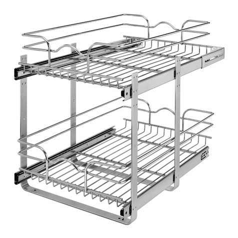
Rev-A-Shelf 5WB2-1522CR-1 User manual

Rev-A-Shelf

Rev-A-Shelf 5WB2-1522CR-1 User manual
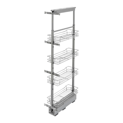
Rev-A-Shelf 5743 User manual

Rev-A-Shelf

Rev-A-Shelf 5743 User manual
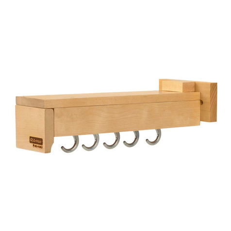
Rev-A-Shelf GLIDEWARE GLD Series User manual
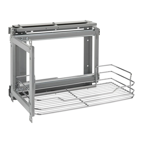
Rev-A-Shelf

Rev-A-Shelf GLIDEWARE GLD Series User manual

Rev-A-Shelf 5708 User manual

Rev-A-Shelf

Rev-A-Shelf 5708 User manual
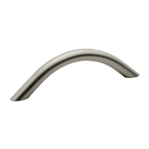
Rev-A-Shelf CHDSL-996-SN-1 User manual
Rev-A-Shelf

Rev-A-Shelf CHDSL-996-SN-1 User manual

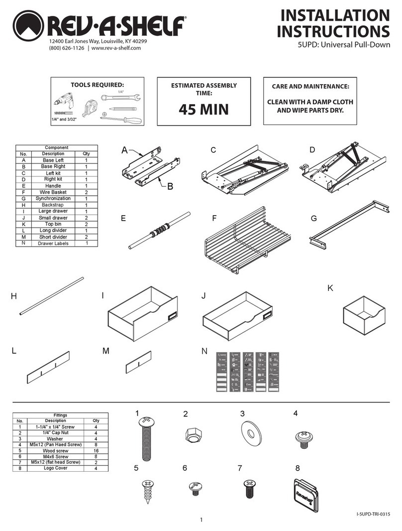
Rev-A-Shelf 5UPD User manual

Rev-A-Shelf

Rev-A-Shelf 5UPD User manual
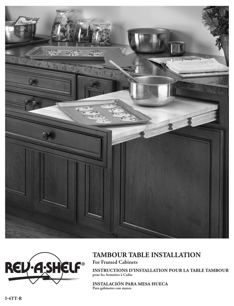
Rev-A-Shelf RS4TT-2133-1 User manual

Rev-A-Shelf

Rev-A-Shelf RS4TT-2133-1 User manual

Rev-A-Shelf GRP21891 User manual

Rev-A-Shelf

Rev-A-Shelf GRP21891 User manual
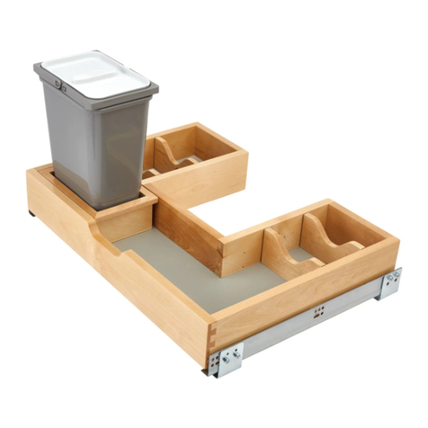
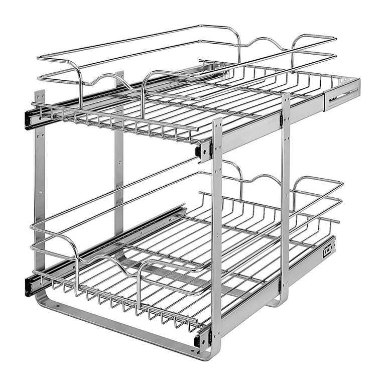
Rev-A-Shelf 486-30VSBSC-BM-1 User manual
Rev-A-Shelf

Rev-A-Shelf 486-30VSBSC-BM-1 User manual

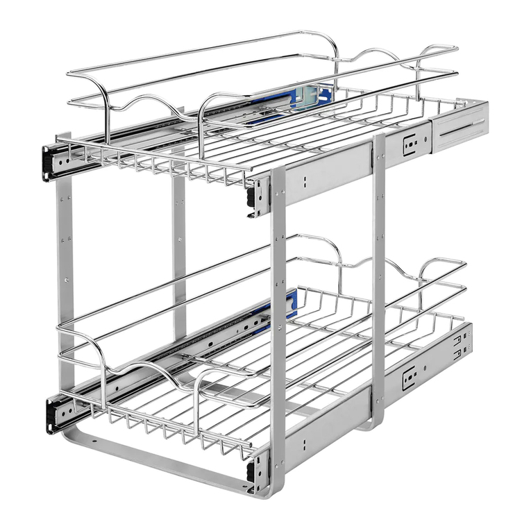
Rev-A-Shelf 9" Two-Tier Basket User manual
Rev-A-Shelf

Rev-A-Shelf 9" Two-Tier Basket User manual

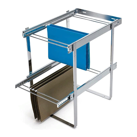
Rev-A-Shelf TWO-TIER BASKET User manual
Rev-A-Shelf

Rev-A-Shelf TWO-TIER BASKET User manual

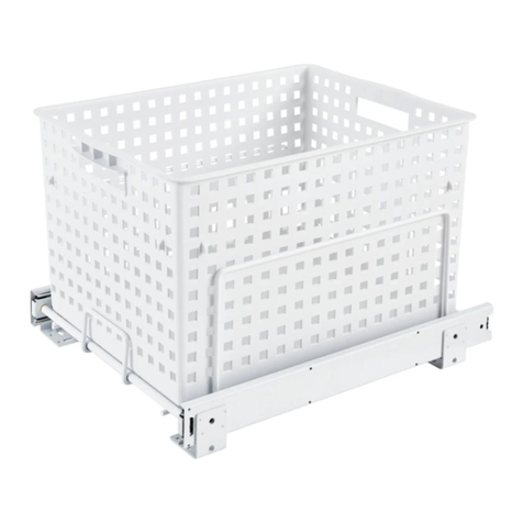
Rev-A-Shelf TWO-TIER FILE DRAWER SYSTEM User manual
Rev-A-Shelf

Rev-A-Shelf TWO-TIER FILE DRAWER SYSTEM User manual

Rev-A-Shelf RV Series User manual

Rev-A-Shelf

Rev-A-Shelf RV Series User manual
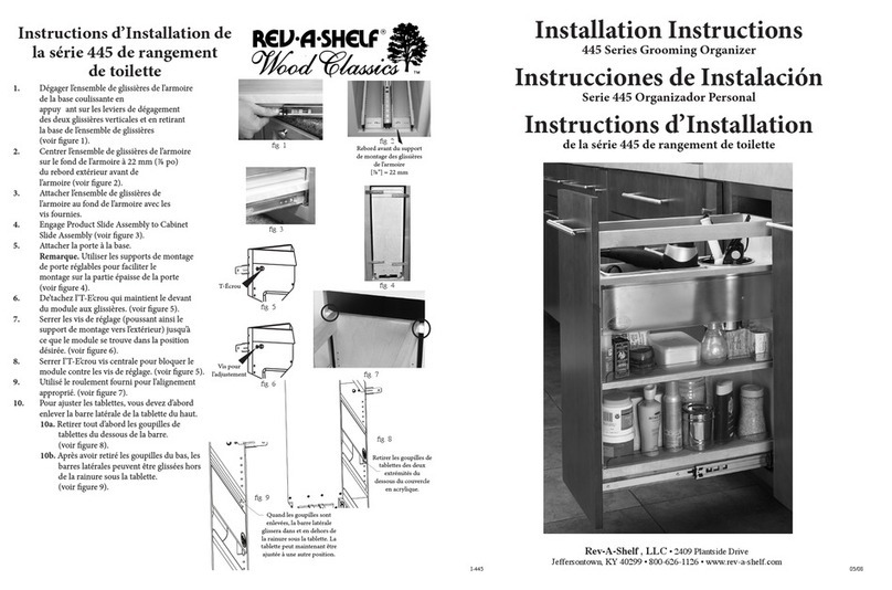
Rev-A-Shelf 445 Series User manual

Rev-A-Shelf

Rev-A-Shelf 445 Series User manual
Rev-A-Shelf 548 Series User manual

Rev-A-Shelf

Rev-A-Shelf 548 Series User manual
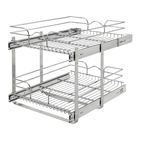
Rev-A-Shelf 5WB-DMKIT User manual

Rev-A-Shelf

Rev-A-Shelf 5WB-DMKIT User manual
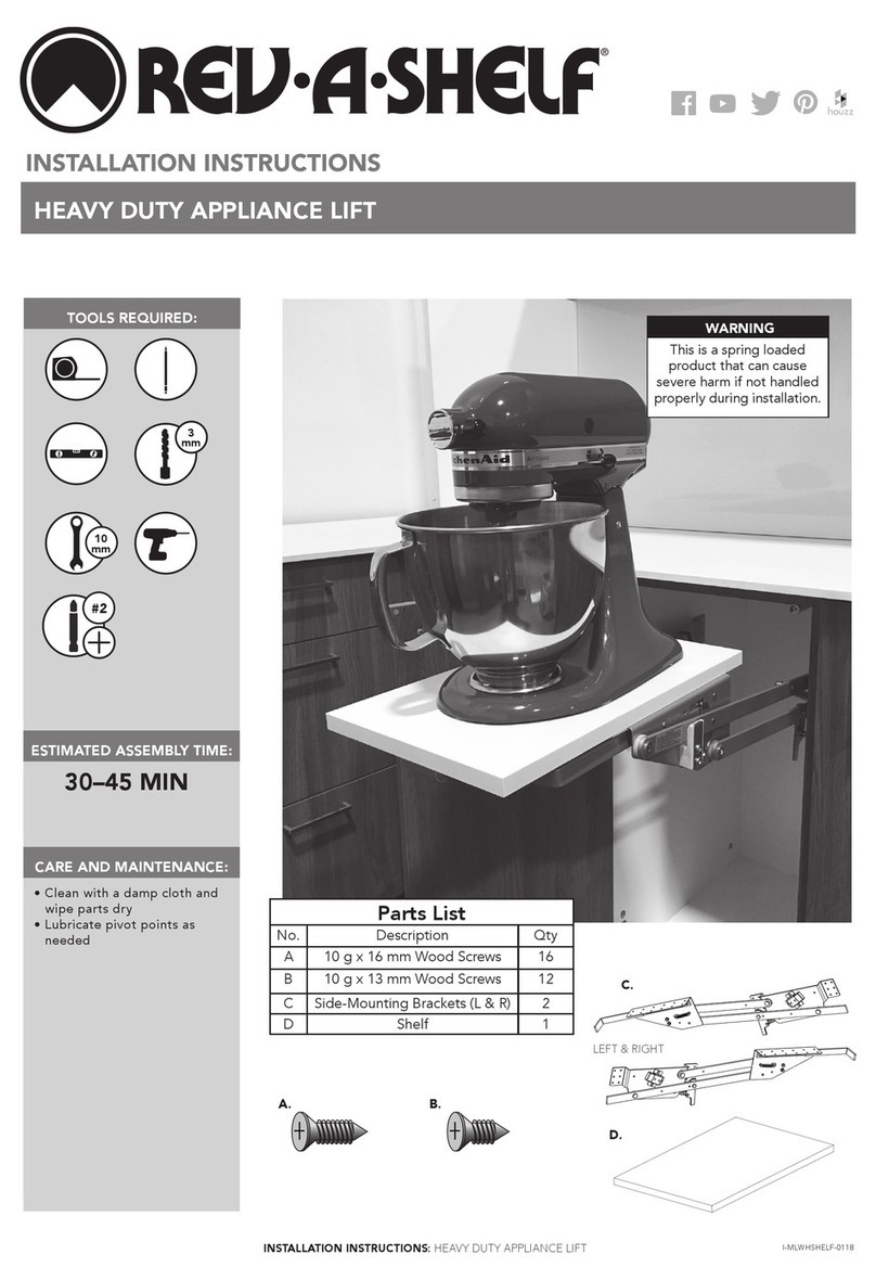
Rev-A-Shelf ML-450SC-WS-1 User manual

Rev-A-Shelf

Rev-A-Shelf ML-450SC-WS-1 User manual

Rev-A-Shelf 4SOWC8 User manual

Rev-A-Shelf

Rev-A-Shelf 4SOWC8 User manual
Rev-A-Shelf Wood Classics 432 Series User manual

Rev-A-Shelf

Rev-A-Shelf Wood Classics 432 Series User manual

Rev-A-Shelf 448TP User manual

Rev-A-Shelf

Rev-A-Shelf 448TP User manual

Rev-A-Shelf Closet User manual

Rev-A-Shelf

Rev-A-Shelf Closet User manual

Rev-A-Shelf 5743 User manual

Rev-A-Shelf

Rev-A-Shelf 5743 User manual

Rev-A-Shelf 4WDBSC Series User manual

Rev-A-Shelf

Rev-A-Shelf 4WDBSC Series User manual

Popular Indoor Furnishing manuals by other brands

Regency LWMS3015 Assembly instructions

Regency

Regency LWMS3015 Assembly instructions

Furniture of America CM7751C Assembly instructions

Furniture of America

Furniture of America CM7751C Assembly instructions

Safavieh Furniture Estella CNS5731 manual

Safavieh Furniture

Safavieh Furniture Estella CNS5731 manual

PLACES OF STYLE Ovalfuss Assembly instruction

PLACES OF STYLE

PLACES OF STYLE Ovalfuss Assembly instruction

Trasman 1138 Bo1 Assembly manual

Trasman

Trasman 1138 Bo1 Assembly manual

Costway JV10856 manual

Costway

Costway JV10856 manual
moss DESIGN Caisson Credenza Assembly instructions

moss DESIGN

moss DESIGN Caisson Credenza Assembly instructions

Aquaglide FULL DECK 15.0 owner's manual

Aquaglide

Aquaglide FULL DECK 15.0 owner's manual

AREBOS AR-HE-SW30 user manual

AREBOS

AREBOS AR-HE-SW30 user manual

Till-Hilft Fulda 87005.330 Assembly instructions

Till-Hilft

Till-Hilft Fulda 87005.330 Assembly instructions

Twoey Outside 2010 quick start guide

Twoey Outside

Twoey Outside 2010 quick start guide

Hettich Easys 200 operating instructions

Hettich

Hettich Easys 200 operating instructions

The bedboss RELAX 404 Series owner's manual

The bedboss

The bedboss RELAX 404 Series owner's manual

Oeseder Möbelindustrie Bern 991 720 Assembly instructions

Oeseder Möbelindustrie

Oeseder Möbelindustrie Bern 991 720 Assembly instructions

Costway HW68469 user manual

Costway

Costway HW68469 user manual

Next ALIX A27743 Assembly instructions

Next

Next ALIX A27743 Assembly instructions

BROSA Hans Assembly guide

BROSA

BROSA Hans Assembly guide

Prodigg MINIKA PBA015T-FUR installation manual

Prodigg

Prodigg MINIKA PBA015T-FUR installation manual

manuals.online logo
manuals.online logoBrands
  • About & Mission
  • Contact us
  • Privacy Policy
  • Terms and Conditions

Copyright 2025 Manuals.Online. All Rights Reserved.

TOOLS REQUIRED:
30 MIN
ESTIMATED ASSEMBLY TIME:
CARE AND MAINTENANCE:
• Clean with a damp cloth and
wipe parts dry
• Lubricate pivot points as
needed
GLIDING DRAWER SYSTEM
A.
B.
C.
INSTALLATION INSTRUCTIONS: GLIDING DRAWER SYSTEM I-57XX-0118
D.
#2
3
mm
20180102-1
Component
No. Description Qty
ABasket 1
B Slide 1 Set
CLogo cap 2
D 5/32x18 Wood Screw 16
Component
No. Description Qty
EMounting bracket 1 Set
FDoor mounting bracket 1 Set
GM4x6mm Machine screw 4
HM4x4.5L Screw (Spare Parts) 2
1/2
(5730-450SC-CW-1)
(5786-900SC-CW-1)
A
A
B
CD
EFG
FOR DOOR MOUNTING ONLY
H
20180102-1
Component
No. Description Qty
ABasket 1
B Slide 1 Set
CLogo cap 2
D5/32(4mm)x18 Wood Screw 16
Component
No. Description Qty
EMounting bracket 1 Set
FDoor mounting bracket 1 Set
G M4x6mm Machine screw 4
HM4x4.5L Screw (Spare Parts) 2
1/2
(5730450SC)
(5786900SC)
A
A
B
CD
EFG
FOR DOOR MOUNTING ONLY
H
20180102-1
Component
No. Description Qty
ABasket 1
B Slide 1 Set
CLogo cap 2
D 5/32x18 Wood Screw 16
Component
No. Description Qty
EMounting bracket 1 Set
FDoor mounting bracket 1 Set
GM4x6mm Machine screw 4
HM4x4.5L Screw (Spare Parts) 2
1/2
(5730-450SC-CW-1)
(5786-900SC-CW-1)
A
A
B
CD
EFG
FOR DOOR MOUNTING ONLY
H
20180102-1
Component
No. Description Qty
ABasket 1
B Slide 1 Set
CLogo cap 2
D 5/32x18 Wood Screw 16
Component
No. Description Qty
EMounting bracket 1 Set
FDoor mounting bracket 1 Set
GM4x6mm Machine screw 4
HM4x4.5L Screw (Spare Parts) 2
1/2
(5730-450SC-CW-1)
(5786-900SC-CW-1)
A
A
B
CD
EFG
FOR DOOR MOUNTING ONLY
H
20180417-1
Component
No. Description Qty
ABasket 1
B Slide 1 Set
CLogo cap 2
D5/32(4mm)x18 Pan Head Wood Screw 16
EMounting bracket 1 Set
Component
No. Description Qty
FDoor mounting bracket 1 Set
GM4x6mm Machine screw 4
HM4x4.5L Screw (Spare Parts) 2
I Small bin 1
JDouble sided tape 2
1/2
(5730450SC)
(5786900SC)
A
A
B
CD
EFG
FOR DOOR MOUNTING ONLY
H
IJ
G.
FOR DOOR MOUNTING ONLY:
20180102-1
Component
No. Description Qty
ABasket 1
B Slide 1 Set
CLogo cap 2
D 5/32x18 Wood Screw 16
Component
No. Description Qty
EMounting bracket 1 Set
FDoor mounting bracket 1 Set
GM4x6mm Machine screw 4
HM4x4.5L Screw (Spare Parts) 2
1/2
(5730-450SC-CW-1)
(5786-900SC-CW-1)
A
A
B
CD
EFG
FOR DOOR MOUNTING ONLY
H
H.
20180102-1
Component
No. Description Qty
ABasket 1
B Slide 1 Set
CLogo cap 2
D 5/32x18 Wood Screw 16
Component
No. Description Qty
EMounting bracket 1 Set
FDoor mounting bracket 1 Set
GM4x6mm Machine screw 4
HM4x4.5L Screw (Spare Parts) 2
1/2
(5730-450SC-CW-1)
(5786-900SC-CW-1)
A
A
B
CD
EFG
FOR DOOR MOUNTING ONLY
H
I.
20180102-1
Component
No. Description Qty
ABasket 1
B Slide 1 Set
CLogo cap 2
D 5/32x18 Wood Screw 16
Component
No. Description Qty
EMounting bracket 1 Set
FDoor mounting bracket 1 Set
GM4x6mm Machine screw 4
HM4x4.5L Screw (Spare Parts) 2
1/2
(5730-450SC-CW-1)
(5786-900SC-CW-1)
A
A
B
CD
EFG
FOR DOOR MOUNTING ONLY
H
F.
1 BASKET INCLUDED, 2 UNITS SHOWN 5786-900-CW-1 (2)
5730
5786
Parts List
No. Description Qty
A Shelves 1
B Slide Set 1 Set
C Logo Caps 2
D 4G x 18 mm Pan Head Wood Screws 16
E Small Bin 1
F M4 x 4.5 mm Pan Head Screws 2
G Mounting Bracket 1 Set
H Door Mounting Bracket 1 Set
I M4 x 6 mm Machine Screws 4
J Double Sided Tape 2
E.
J.
B.
20180417-1
Component
No. Description Qty
ABasket 1
B Slide 1 Set
CLogo cap 2
D5/32(4mm)x18 Pan Head Wood Screw 16
EMounting bracket 1 Set
Component
No. Description Qty
FDoor mounting bracket 1 Set
GM4x6mm Machine screw 4
HM4x4.5L Screw (Spare Parts) 2
I Small bin 1
JDouble sided tape 2
1/2
(5730450SC)
(5786900SC)
A
A
B
CD
EFG
FOR DOOR MOUNTING ONLY
H
IJ
2
FIGURE B
Using measurements from Figure B
predrill hole locations and install
the slides using (6) 4G x 18 mm Pan
Head Screws.
STEP 1
#2
3
mm
Place the back of the shelves
on the back of the slides. This
engages the hook mechanism,
then press the slides down. You
will hear a click, and the slides
are engaged. (See Figure C)
STEP 2
20180102-1
STEP 1. STEP 2.
STEP 3.
2/2
STEP 4.
Side Mounted
D
X6
C
A
B
6
5
287
189
92
FIGURE C
CHOOSING THE DESIRED
BOTTOM FOR THE UNIT
20180102-1
M4x4.5L Screw
M4x4.5L Screw
20180102-1
M4x4.5L Screw
M4x4.5L Screw
Unscrew the M4 x 4.5 mm Pan Head
Screws from the bottom of the shelf,
choose the desired color by ipping
the shelf and reinstall the bottom
shelf. (See Figure A)
FIGURE A
M4 x 4.5mm Screw
20180102-1
STEP 1. STEP 2.
STEP 3.
2/2
STEP 4.
Side Mounted
D
X6
C
A
B
6
5
287
189
92
20180102-1
STEP 1. STEP 2.
STEP 3.
2/2
STEP 4.
Side Mounted
D
X6
C
A
B
6
5
287
189
92
Press down so the slides are
fully engaged
3
STEP 4
Remove the logo caps from the unit,
by popping them off. Once the caps
are removed, secure the mounting
brackets to the unit with (4) M4 x 6
mm machine screws. (See Figure E)
Reattach the logo caps
FIGURE E
20180102-1
Door Mounting
STEP 1.
STEP 3.
STEP 2.
STEP 4.
ACH
G
DX8
H
I
mm141
mm
501
mm58
5730-450 (334 mm)
5730-500 (384 mm)
5730-600 (484 mm)
5730-800 (684 mm)
5730/5786-900 (784 mm)
STEP 3
Use the images in Figure D to adjust
the slides based on the cabinet
thickness of 16 mm, 18 mm,
or 20 mm. Side Panel
16/18/20 mm 16/18/20 mm
16 mm
18 mm
20 mm
The bluge
slot
16 mm 18 mm
20 mm
Side Panel
16/18/20 mm 16/18/20 mm
16 mm
18 mm
20 mm
The bluge
slot
16 mm 18 mm
20 mm
Side Panel
16/18/20 mm 16/18/20 mm
16 mm
18 mm
20 mm
The bluge
slot
16 mm 18 mm
20 mm
Side Panel
16/18/20 mm 16/18/20 mm
16 mm
18 mm
20 mm
The bluge
slot
16 mm 18 mm
20 mm
FIGURE D
DOOR MOUNTING
(NOT REQUIRED)
4
DOOR ADJUSTMENT
If the cabinet door is not lining up
correctly, use the images in
Figure H to loosen and tighten the
door mounting screws to properly
align the cabinet door.
FIGURE H
STEP 5
Using measurements from
Figure F predrill hole locations, be
careful not to drill through door.
Attach the door mounting brackets
to the cabinet door with (8) 4G x 18
mm Pan Head Screws.
#2
3
mm
20180102-1
Door Mounting
STEP 1.
STEP 3.
STEP 2.
STEP 4.
ACH
G
DX8
H
I
mm141
mm
501
mm58
5730-450 (334 mm)
5730-500 (384 mm)
5730-600 (484 mm)
5730-800 (684 mm)
5730/5786-900 (784 mm)
FIGURE F
The mounting dimensions will vary based on the
unit that was purchased. Follow the dimensions on
the image for the appropriate mounting dimensions
based on the unit you have. The mounting brackets
height measurements are from the bottom of the
cabinet door to the center of the 3 wide holes on
the brackets.
STEP 6
Loosen the bracket screws on the
mounting bracket engage the hook
of the door mounting bracket onto
the mounting bracket, and tighten the
screw to secure the door to the unit.
(See Figure G)
FIGURE G
20180102-1
Door Mounting
STEP 1.
STEP 3.
STEP 2.
STEP 4.
AC
H
G
DX8
H
I
mm141
mm
501
mm58
5730-450 (334 mm)
5730-500 (384 mm)
5730-600 (484 mm)
5730-800 (684 mm)
5730/5786-900 (784 mm)