Revolabs 10-FLX2-200-VOIP Parts list manual

REVOLABS FLX2
TM
Wireless Conference System
for Voice over IP
System Guide
Models:
10-FLX2-200-VOIP 10-FLX2-020-VOIP 10-FLX2-002-VOIP 10-FLX2-101-VOIP
10-FLX2-200-DUAL-VOIP

2
© 2011 - 2013 REVOLABS, INC. All rights reserved. No part of this document may be
reproduced in any form or by any means without express written permission from
Revolabs, Inc. Product specifications are subject to change without notice.
Revolabs FLX2 System Guide – VOIP
10-FLX2SYSGUIDEVoIP-EN
May 2014 (Rev 2.1.2)

3
Introduction
Congratulations on your purchase of the Revolabs FLX2
TM
Wireless Conference Phone.
This system utilizes state of the art technology providing high band-width audio and
enabling clear, reliable, un-tethered communications with your telephone, PC, mobile
device, and video conferencing system.
The Revolabs FLX2 Conferencing Phone allows enhanced freedom for VoIP calls and
video conferences by allowing independent locations of the microphones and the
speaker used during the call.
The FLX2 Conference Phone utilizes encrypted digital communication for its wireless
transport, ensuring highest security for your conversations. The FLX2 Conference
Phone is a flexible solution for all your communication needs, allowing it to be used in
your VoIP telephone network, for your video conferences, and with your Bluetooth
enabled cell phone or computer.
Welcome to the 21
st
century Unified Communications Technology!
Please read this documentation carefully and follow the instructions before using your
FLX2 Wireless Conference phone.
Safety Warnings
•Do not expose any of the FLX2 components to water, moisture, or high humidity.
•Do not expose any of the FLX2 components to extreme high or low temperatures.
•Do not expose any of the FLX2 components to lit candles, cigarettes, cigars, or to
open flames, etc.
•Do not drop, throw, or try to bend any of the components, as rough treatment could
damage them.
•Do not open the casings of any of the components of the FLX2 Conference Phone
•Do not use any other accessories than Revolabs’ originals intended for use with
this product. Use of non-original accessories may result in loss of performance,
damage to the product, fire, electric shock or injury. The warranty does not cover
product failures which have been caused by use of non-original accessories.
•Only use the power adapter provided to connect the components to the electric
mains.
•Do not open or try to modify any of the batteries delivered with the FLX2
Conference Phone components. Replace batteries only with Revolabs approved
batteries.
•Extreme heat, short circuits, or any attempt to open or modify the batteries might
cause them to ignite or explode.

4
Contents
Introduction ............................................................................................................................................ 3
Safety Warnings ..................................................................................................................................... 3
Contents .................................................................................................................................................... 4
General Information ............................................................................................................................ 6
Quick setup for VoIP Conference Calls...........................................................................................
Description ............................................................................................................................................ 10
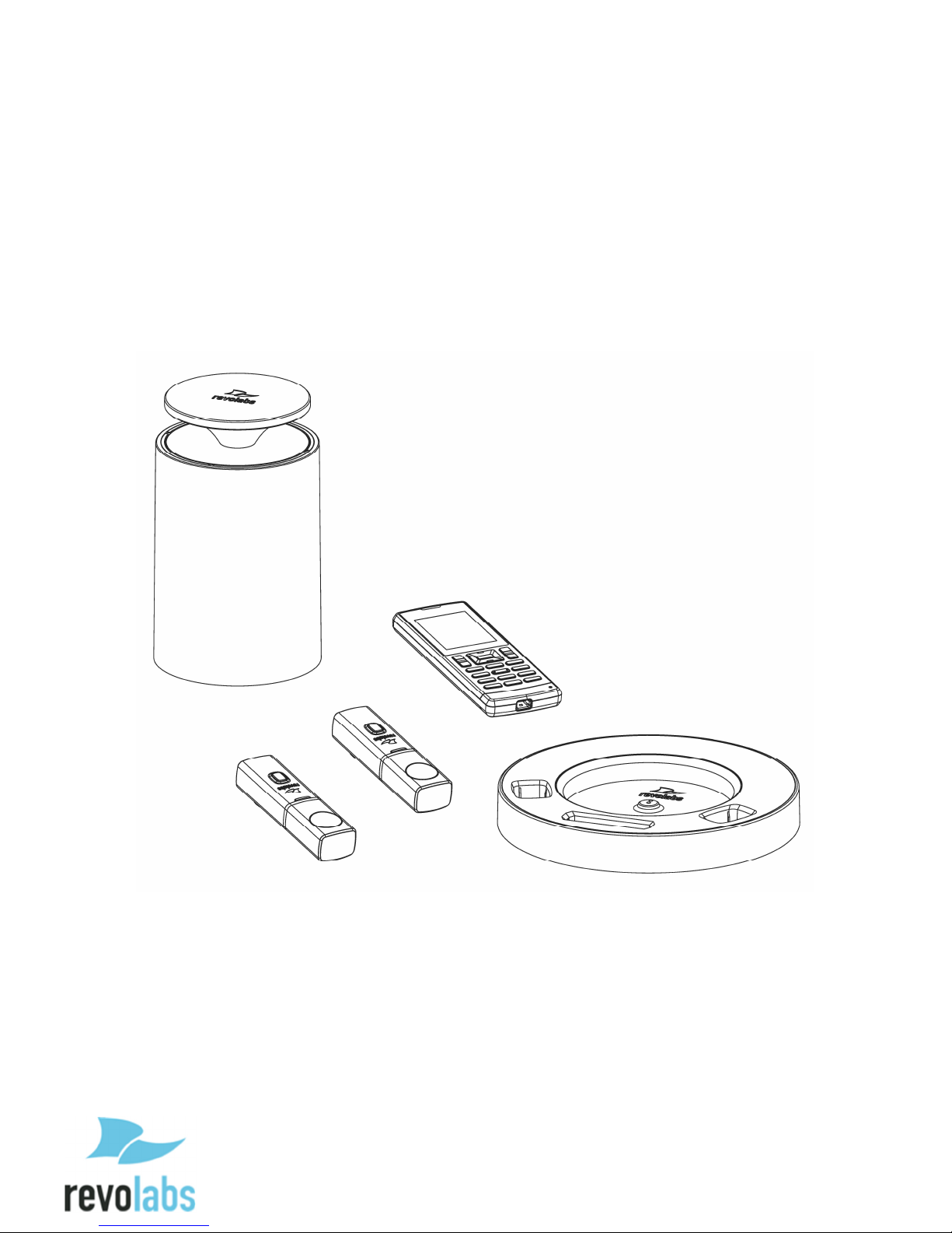
Unpacking ......................................................................................................................................................... 10
Installing FLX2 Components ........................................................................................................... 11
FLX2 Base Station .......................................................................................................................................... 11
FLX2 Charger Base ......................................................................................................................................... 12
FLX Dialer ......................................................................................................................................................... 13
FLX Speaker ..................................................................................................................................................... 14
FLX Microphones ........................................................................................................................................... 15
VoIP configuration ........................................................................................................................................ 16
Managing A Call .................................................................................................................................... 18
Calling Configurations .................................................................................................................................. 18
FLX Home Screen ........................................................................................................................................... 19
Placing a VoIP Call ......................................................................................................................................... 21
Answering an Incoming Call ...................................................................................................................... 21
Declining an Incoming VoIP Call .............................................................................................................. 22
Ending a Telephone call .............................................................................................................................. 23
Calling a Directory Contact ......................................................................................................................... 23
Active Call Management .............................................................................................................................. 23
Component behavior in and out of the Charger Base ....................................................................... 26
Bluetooth ................................................................................................................................................ 2
Activating Bluetooth ..................................................................................................................................... 2
Managing the Device Registry ................................................................................................................... 2
Making a call via Bluetooth ........................................................................................................................ 30
Answering a call via Bluetooth ................................................................................................................. 30
Video Conference Collaboration .................................................................................................... 31
Connecting a Video Conference System ................................................................................................. 31
Configuring the Analog Audio ................................................................................................................... 31
Making a Video Call ....................................................................................................................................... 31
Mixing the audio signals .............................................................................................................................. 32
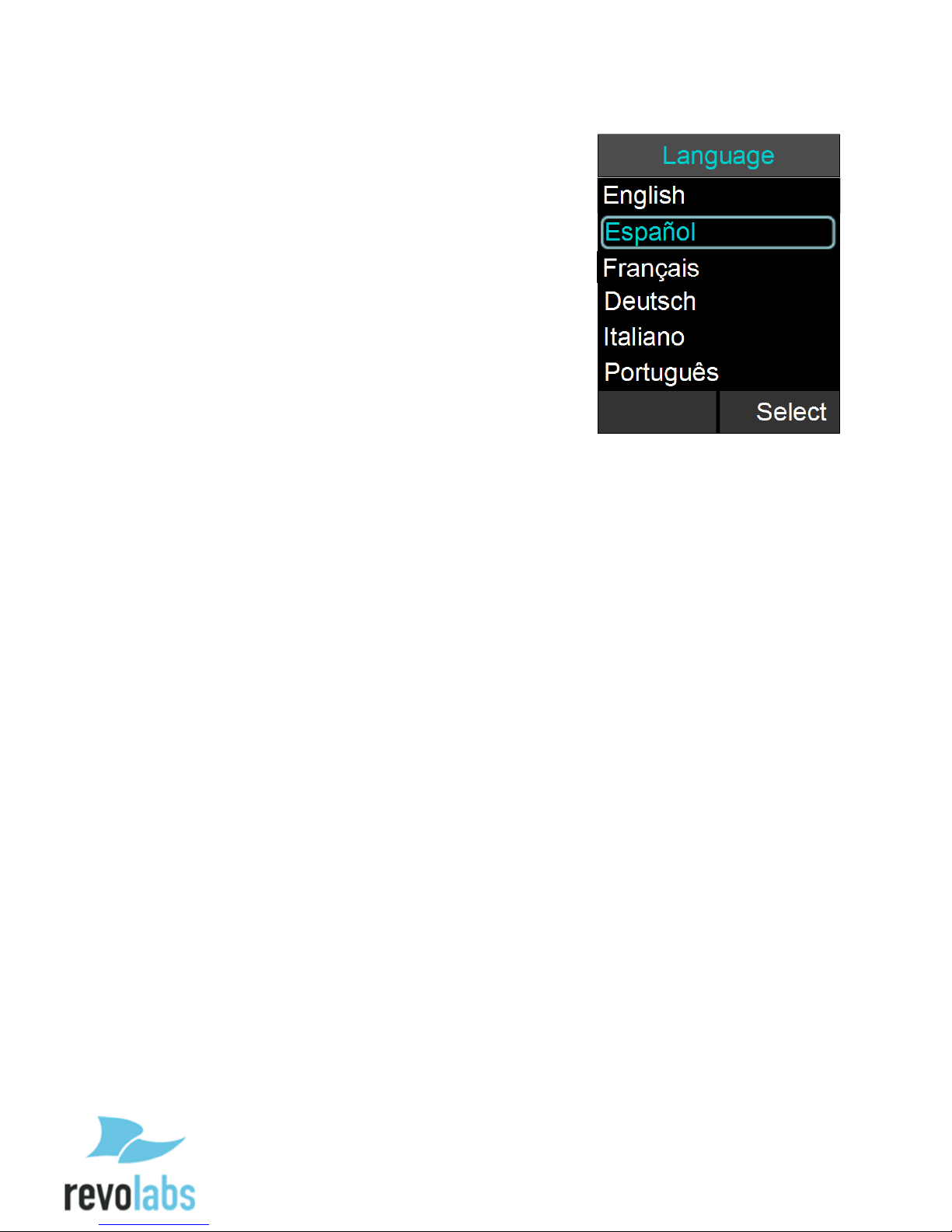
FLX2 System Configuration.............................................................................................................. 33
Menu Hierarchy .............................................................................................................................................. 33
Menu Navigation ............................................................................................................................................ 33
Recent Calls ...................................................................................................................................................... 34
Contacts ............................................................................................................................................................. 36
Audio Control .................................................................................................................................................. 39
Device Status ................................................................................................................................................... 41
System Information ...................................................................................................................................... 41

5
Home .................................................................................................................................................................. 42
Call ....................................................................................................................................................................... 42
Setup ................................................................................................................................................................... 42
Web Interface ....................................................................................................................................... 52
Enabling Web Access .................................................................................................................................... 52
Connecting to the FLX Web Interface...................................................................................................... 52
Home Page ........................................................................................................................................................ 54
User Settings .................................................................................................................................................... 54
Administrator Settings ................................................................................................................................ 58
Power On/Off the System Components ....................................................................................... 6
Battery Exchange .................................................................................................................................
Microphones .................................................................................................................................................... 8
Dialer .................................................................................................................................................................. 8
Speaker .............................................................................................................................................................. 9
Connecting using AUX IN / AUX OUT ............................................................................................ 9
Troubleshooting .................................................................................................................................. 81
Warning Messages ......................................................................................................................................... 81
Microphone, Speaker, or Dialer not connecting to Base Station .................................................. 82
Microphone, Speaker, or Dialer not paired with Base Station ...................................................... 82
LED Indicators ................................................................................................................................................. 83
Reset to Factory Defaults ............................................................................................................................ 85
Technical Specifications ................................................................................................................... 85
Models ................................................................................................................................................................ 85
Regulatory Information .................................................................................................................... 88
FCC Notice to Users ........................................................................................................................................ 88
Industry Canada Notice to Users .............................................................................................................. 89
Restricted use with certain medical devices ....................................................................................... 90
Export Law Assurance .................................................................................................................................. 90
Limited Warranty and Limitation of Liability ........................................................................... 92
GPL LICENSED SOFTWARE ............................................................................................................... 94
GNU GENERAL PUBLIC LICENSE ................................................................................................................ 94
Technical Support ............................................................................................................................... 99

6
General Information
The Revolabs FLX2 Conference Phone includes several components which, in the sum,
make up the conferencing phone. The components are the Charger Base, Speaker,
Microphones, and Dialer (handset).
In addition, the Base Station receives the wireless signals from those components and
connects to your VoIP network for conference calls, with your video conferencing unit to
provide outstanding audio for your video calls, or to your Bluetooth enabled device such
as a cell phone or computer.

7
Quick setup for VoIP Conference Calls
While all components delivered with the Revolabs FLX2 Conference Phone are partially
charged, we recommend charging the Speaker, the Microphones, and the Dialer for at
least 8 hours or overnight before starting to use the system.
Connecting the Base Station
Place the Base Station close to the Ethernet outlet
you want to use for the conference phone.
Connect the Base Station to the network using the
provided Ethernet cable. The Base Station is
powered using Power over Ethernet (PoE). If the
base station does not power up after you connect
it to the network outlet, this outlet might not be
providing PoE. Please check with your IT
department that PoE is available.
If your network does not support PoE, Revolabs
provides a power injector that can be bought
through your reseller, which adds the necessary
power to that Ethernet connection.
Connecting the Charger Base
Place the Charger Base at a location where you
can easily access the Microphones and the
Speaker for your conference calls, e.g. on a side
board, a desk, or the conference table. Connect
the Charger Base to a power outlet using the
provided power supply. Place the Speaker, the
Microphones, and the Dialer in the respective
openings of the Charger Base to charge them.
The Dialer and Speaker will automatically connect
to the Base Station after a short time if it is
powered up. You will hear a confirmation chime
from the Speaker once the system is ready for
use. If the Speaker or the Dialer is not powered
up, take them out of the Charger Base for a few
seconds and put them back in. This will switch on
the component.
To switch on the microphones
take them out of the charger
base. They will automatically
power up and connect to the
base station.

Phone configuration
Before using the FLX for the first time, you will need to
select the system language. The six options are English,
Español (Spanish), Français (French), Deutsch
(German), Italiano (Italian), and Português (Portuguese).
Highlight the language of your choice, and press either
“Enter” or “Select” on the Dialer to select it. Once a
language is select, the system will use that language for
all screen contents. Please ensure that you selected the
right one. If the wrong language was selected, it can be
changed in the advanced setup menu of the handset
(see page 44), however you will have to navigate
through the screens using the selected language to get
there.
VoIP configuration
Depending on your switch different settings will be required for your FLX to work in your
environment. First of all, the FLX will require an IP address. The IP address can either
be obtained from a DHCP server in your network, or be statically set on the phone. The
phone is preset to DHCP. If you want to change this, please open the menu on the
handset by pressing the right soft key, go to the ‘Setup’ menu, and select ‘Advanced
Setup’. You will have to enter a password, which is preset to 7386. Now select
‘Network Settings’. Under ‘IP Settings’ you can set the required network values like IP
address, subnet mask, Default Gateway, and DNS servers. You will need to restart the
phone for any changes you made in this section to take effect.
If you are using DHCP, you can go to the System Info menu, and select About System.
The assigned IP address for the FLX will be shown here. If you configured a VLAN
(Virtual LAN) for your voice traffic on your IP network, you need to either enable VLAN
on the FLX dialer and provide the VLAN identifier, or select “Automatic”, in which case
the FLX will try to determine the VLAN settings of your network at startup.
Independent on how the IP address of your system was assigned, the FLX phone has
to be configured to work in your VoIP environment. You will also have to enable the
extension (user) you want to use with the FLX on your switch. Please review your
switch documentation on information on how to do that. For the minimal setup, in the
FLX Handset you will have to provide information on the IP connection to the telephone
switch. To do this visit Setup – Advanced Setup – Network Settings – VOIP Settings.
Under Registrar, provide the IP address or host name of your IP PBX. Username
should be the extension or name under which you want to register this phone on the IP
PBX. In Password, provide the password for this username. If no values are provided
for ID and Display Name, the Username entry will be used for them. Select ‘Reload
Settings’ after you have set the values in the handset, which will restart the base.
If further settings are required to connect the FLX phone to your IP PBX, like a Proxy
server, please visit the FLX Web Interface as described on page 52. You get to this
interface by entering the IP address of the FLX into the web browser of your choice.
After you entered the password (7386, unless you changed it in the handset), you can

9
find the SIP settings under the Administrator tab on the top right. You will find the
different SIP settings under SIP Registration, SIP Configuration, Transport, and Media.
You have to press ‘Save’ an every page where you changed an entry to save these
changes. If you do not press ‘Save’, the changes will be lost when you leave that page.
Restart the phone once you are finished with your changes.
Note: For some of the common IP PBXs, Revolabs provides
documents on required settings for the FLX and the IP PBX.
The documents can be found on the support website at
http://www.revolabs.com/Support/Product-Line/FLX.aspx.
Once the FLX is registered with the IP PBX, it will display the ID in the screen and is
ready to make and receive phone calls.
Making a call
To make a conference call, take at least one of the Microphones out of the Charger
Base, and take the Dialer out of the Charger Base. You can remove all Microphones
and the Speaker if you wish, but this is not required. Use the Dialer to enter the number
you want to call, including any leading digits your VoIP telephone switch might require.
The Speaker and any Microphone that is not in the Charger Base will be active during
the call. To finish a conference call, press the red hang-up button on the Dialer.
NOTE: It is also possible to have a conference call with the
microphones in the charger base. However, due to the proximity
of microphone and speaker at that time, audio quality might be
impacted. The maximum volume of the speaker is limited while
the microphones are in the charger base. Microphones that are
placed into the charger base are switched off. To use
microphones in the charger base for phone calls they first have
to be switched on. You do this by pressing the button on the
microphone while it is in the charger. The microphone will start
in a muted state. Once it starts blinking red, unmute it by
pressing the mute button once again. Microphones in the
charger base never transmit audio to the AUX OUT connector.
If any microphone is active outside of the charger base,
microphones in the charger base cannot be activated (unmuted)
for the call.
To make a call using the Dialer as a handset, make sure that all Microphones are in the
Charger Base before starting to dial the number. At this point, only the Dialer will be
used for the call. To end the call, press the red hang-up button on the Dialer.
At any time during a call you can toggle between handset and conference phone mode
using the buttons on the Dialer.
To answer a call using the conference phone, simply remove one or more Microphones
from the Charger Base when the Speaker rings. If a microphone is already out of the

10
charger base when an incoming call comes in, pressing the button on the microphone
will answer the call in conference phone mode. You can also use the Dialer to answer
the call by pressing the green call button on the handset. If all microphones are in the
charger at this time, the call will be answered using the handset mode. If at least one
microphone is switched on and not in the charger base, this will answer the call in
Conference phone mode.
Description
The Revolabs FLX2™Wireless Conference Phone is a unique marriage of innovative
technology and ergonomic design, allowing for an unparalleled experience when
making telephone calls, video conference calls, or using it with your Bluetooth enabled
cell phone or computer to make speaker phone calls.
The technology used allows the Microphones, the Dialer, and the Speaker to co-exist
with other wireless products such as wireless LANs (802.11b&g) without interference.
The Revolabs FLX2 Conference Phone includes digital encryption technology to ensure
secure wireless communications between the Microphones, Speaker and the Base
Station.
Unpacking
Your Revolabs FLX2™ Conference Phone package contains the following items. When
unpacking the system be sure to take inventory of all parts to ensure that nothing is
missing. If parts are missing, please contact your retailer.
•FLX2 Base Station
•FLX2 Charger Base
•FLX Speaker
•FLX Dialer
•2 FLX Microphones
•1 12-15V AC adapter for the Charger Base
•Ethernet cable
•Quick Setup Guide
•Quick User Guide
The 10-FLX2-200-DUAL-VOIP additionally includes:
•A second FLX2 Charger Base
•A second FLX Speaker
•A second 12-15V AC adapter for the Charger Base

11
Installing FLX2 Components
The Revolabs FLX2
TM
System is comprised of several components that work together to
provide you with a great wireless conferencing system. These components must be
setup correctly for optimal performance of the system.
FLX2 Base Station
The Base Station is the wireless receiver and sender of the audio stream from the
Microphones and to the Speaker, as well as to the Dialer. It features the ability to
connect two Revolabs FLX Microphones and one Speaker wirelessly.
The Base Station is designed to optimize audio and video conferencing by providing
consistent audio input from all participants.
The FLX2 VoIP Base Station is shown in rear panel view below. It is equipped with an
Ethernet/power connection, two mini-USB ports for firmware updates, and analog audio
input/output connections for video conferencing collaboration or for recording.
NOTE: The Base Station comes equipped with the necessary
cables and power supplies to perform a VoIP conference call.
Other types of conference calls performed with FLX2 may
require additional cables that are not part of the delivery.

12
FLX2 Charger Base
The FLX2 Charger Base, shown below, provides charging capabilities for all battery
operated system components, including the Dialer, the Speaker, and the Microphones,
by allowing them to charge in one simple and organized location.
The FLX2 Charger Base is not required while in a conference call, however it can
maintain the charge of the FLX Speaker and FLX Dialer while a call is in progress. The
Charger Base is equipped with a DC power connection and a mini-USB connection for
firmware updates to the Dialer.

13
FLX Dialer
The FLX Dialer equips the user with an intuitive and interactive tool for configuring and
operating the FLX System.
The Dialer is not only used to make and answer conference calls, but it is also used for
configuring the system settings, having a call using the handset, and monitoring the
system components.
The FLX Dialer, shown below, is composed of several parts such as a color LCD
screen, a compilation of buttons, and a microphone and handset speaker.

14
FLX Speaker
The FLX Speaker, shown below, is a wireless active omnidirectional speaker that has
been designed and optimized specifically for use with the FLX Conferencing System.
The Speaker is equipped with a pairing button on the bottom and 4 LED indicators on
the top to display the activity of the Speaker and the mute status of the system. The
Speaker can operate in or out of the Charger Base during conference calls.

15
FLX Microphones
The FLX Microphones provide a sleek and unobtrusive form factor allowing for closer
proximity to the participants and creating the best audio available to the far end. They
are equipped with a button for pairing and muting, an LED indicator to display mute
status and battery charge level, and an internal buzzer to warn if the Microphones have
lost connection to the Base Station.
The FLX Microphones, shown below, come in three different versions to provide a
flexible solution to meet all applications of conferencing spaces. Microphone types
include an omnidirectional tabletop Microphone, a directional tabletop Microphone, and
a wearable lapel style Microphone. Any combination of two FLX Microphones can be
used with a FLX2 System as they are mix and match.
FLX Microphones will operate in or out of the Charger Base. It is recommended to
always remove the microphones from the charger tray for conference calls as audio on
the speaker and the microphones is limited while in the charger base. When using
Microphones in the charger tray system behavior is automatically adjusted to the close
proximity of speaker and microphones. See the note on page 9 on how to activate
microphones in the charger.
Omnidirectional
Tabletop
Microphone
Directional
Tabletop
Microphone
Wearable Lapel
Microphone

16
Initial Setup
After unpacking the FLX2 Conferencing System, there are a few initial setup tasks that
must be performed before a call can take place or any system configuration can be
changed.
Connecting System Cables
The FLX2 Charger Base has a power supply that needs to be connected, as shown
below. In addition, the Base Station needs to be connected to the network using the
provided Ethernet cable before a conference call can be made. The FLX unit expects
Power over Ethernet (PoE) to be provided through the network connection. If your
network does not support PoE, a power injector is required. Please contact your
reseller to purchase the additional PoE power injector. The Base Station offers
additional optional connections that are only being used when the FLX2 System for
example is connected to a video conferencing unit or a recording device. The cables
required for these connections are not included with the FLX2 system and need to be
purchased separately.
System Setup
Before using the FLX2 to make a call, you will need to select the system language to be
used for the screens. The six options are English, Español
(Spanish), Français (French), Deutsch (German), Italiano
(Italian), and Português (Portuguese). Please highlight the
language of your choice and press ‘Enter’ or ‘Select’.
Note: If a wrong language was selected at this time, it can be
change it later on in the admin area of the menu. However, you
will have to navigate through the menu to get to that option using
the language you selected. So be careful that you do not select a
language you are unfamiliar with.
VoIP configuration
For the FLX phone to work within a VoIP environment the
phone has to be set up to communicate to the IP PBX. You

17
will also have to enable the extension (user) you want to use with the FLX on your PBX.
Please review your PBX documentation on information on how to do that.
From the FLX Handset
Depending on your IP PBX, different settings will be required for your FLX to work in
your environment. First, the FLX will require an IP address. The IP address can either
be obtained from a DHCP server in your network, or be statically set on the phone. The
phone is preset to DHCP. If you want to change this setting, open the menu on the
Dialer by pressing the right soft key, go to the “Setup” menu, and select “Advanced
Setup.” You will have to enter a password, which is preset to 7386. Switch DHCP OFF,
and then select “Network Settings.” Under “IP Settings” you can set the required
network values like IP Address, Subnet Mask, Default Gateway, and DNS Servers. You
will need to restart the phone for any changes you made in this section to take effect.
If you are using DHCP, you can go to the System Info menu, and select About System.
The assigned IP address for the FLX will be shown here. If you configured a VLAN
(Virtual LAN) for your voice traffic on your IP network, you need to either enable VLAN
on the FLX dialer and provide the VLAN identifier, or select “Automatic”, in which case
the FLX will try to determine the VLAN settings of your network at startup.
If you changed any IP settings, you need to select the ‘Load Settings’ option in the
Network menu, which will reboot your FLX base.
Independent on how the IP address of your system was assigned, the FLX phone has
to be configured to work in your VoIP environment and communicate with your IP PBX.
You will have to enable the extension (user) you want to use with the FLX on your IP
PBX. Please review your IP PBX documentation for information on how to add and
configure users. For the minimal setup, in the FLX Dialer you will have to provide
information on the IP connection to the IP PBX. On the Dialer visit Setup – Advanced
Setup – Network Settings – VOIP Settings. Under Registrar, provide the IP address or
host name of your IP PBX. Username should be the extension or name under which
you want to register this phone on the IP PBX. In Password, provide the password for
this username. If no values are provided for ID and Display Name, the Username entry
will be used for them. Select “Load Settings” after you have set the values in the Dialer,
which will restart the Base Station.
For enhanced settings the Web Interface provided by the FLX needs to be used.
From the FLX Web Interface
If further settings are required to connect the FLX phone to your IP PBX, like a Proxy
server, please visit the FLX Web Interface. You get to this interface by entering the IP
address of the FLX into the web browser of your choice. After you enter the password
(7386, unless you changed it in the Dialer), you can find the SIP configuration items
under the Administrator tab on the top right. You will find the different SIP settings under
SIP Registration, SIP Configuration, Transport, and Media. You have to press “Save” on
every page where you changed an entry to save these changes. If you do not press
“Save,” the changes will be lost when you leave that page. Restart the phone once you
are finished with your changes. Please see page 52 for a description of the FLX Web
Interface.

18
Note: For some of the common IP PBXs, Revolabs provides
documents on required settings for the FLX. The documents can
be found on the support website at
http://www.revolabs.com/Support/Product-Line/FLX.aspx.
Managing A Call
The FLX2 Wireless Conferencing system is equipped with a VoIP interface that allows
the system to make conference calls in a VoIP network. The following are the basic
operational instructions for making and receiving telephone conference calls.
Calling Configurations
The FLX2 Wireless Conferencing system has the ability to make and receive calls in
many different ways. This provides the caller the ability to choose what mode or call
type best suits the needs of each individual call.
Speaker Mode
Speaker mode allows the call to take place using the Speaker and Microphones
provided with the FLX2 System. This allows multiple users, within the conference room,
to participate in the call. It also provides the ability for the Microphones and Speaker to
be located anywhere in the conference room to meet the needs of each meeting. The
call, as well as the Speaker and Microphones, are controlled by the FLX Dialer. The
user can switch between ‘speaker mode’ and ‘handset mode’ while in a call.
Handset Mode
Handset mode allows a telephone call to take place through the handset speaker and
microphone located in the FLX Dialer. This allows a single user to make and receive a
private call. It also provides the ability for the FLX2 System to act as a personal desk
phone. The Microphones and Speaker are not used during a handset call. The user can
switch between ‘speaker mode’ and ‘handset mode’ while actively in a call by using the
key marked ‘‘Handset’ or ‘Speaker’.
NOTE: To switch from a handset call to a speaker call at least
one Microphone should be out of the Charger Base and switched
on, and the Speaker must be switched on. If all Microphones
are in the Charger Base at least one of the Microphones in the
Charger Base has to be activated manually by pressing the
Microphone button before switching from the handset call to a
speaker call.
VoIP Call
The FLX2 Conference Phone allows making conference calls using an Ethernet VoIP
connection. A telephone call can be made using either ‘speaker mode’ or ‘handset
mode’. A telephone call can be made at the same time as a video call. Telephone calls
are controlled via the FLX Dialer.

19
Bluetooth Call
The FLX2 System is equipped with a Bluetooth interface that supports the Hands Free
Profile (HFP). This profile allows the user to make a call through a cell phone, a
computer, or other device via a Bluetooth connection. A Bluetooth call can be made
using ‘speaker mode’ only. A Bluetooth call is controlled by the connected Bluetooth
device. A Bluetooth call can be made at the same time as a video call.
NOTE: Revolabs FLX only supports the Hands Free Profile
(HFP) for Bluetooth 2.0 or higher. Applications that try to use
the Bluetooth connection not using the HFP profile, or that are
using an older HFP / Bluetooth standard are not supported by
the FLX.
Video Conference Call
The FLX2 System can be connected to a 3
rd
party video or PC conferencing system via
the Analog I/O ports located on the FLX2 Base Station. This allows the Microphones
and Speaker to be used as the audio interface for the video conference call. Video
Conference calls are controlled primarily by the video conference system. However,
audio properties can be controlled via the FLX Dialer. While the FLX2 Conference
Phone is connected to a video conferencing device, it might still make and accept calls
over the VoIP connection or via a Bluetooth device.
NOTE: When using the FLX connected through the AUX IN
and AUX OUT to another device, only the FLX speaker can be
used. All other speakers, e.g. in a television set, must be turned
off. To avoid audio problems, any Echo Cancellation provided
on the Video Conferencing unit should be switched off.
NOTE: For security reasons, Microphones will not send any
audio signal to the AUX OUT connector when in the charger.
To receive audio signal on the AUX OUT, microphones have to
be taken out of the Charger Base.
FLX Home Screen
Whenever the FLX is not in a call, the FLX Dialer will show
the FLX Home Screen. The Top of the home screen shows
several symbols, indicating the current status of the FLX
components. From left to right they are an indicators for
each of the possible Speakers, one symbol for each of the
mics, and a charging indicator for the handset itself. The
color of the Speaker and Microphone symbol indicate their
status. A green Speaker indicates that that speaker is
available, a grey one means that this speaker is not available, e.g. no speaker is paired

20
or the speaker is switched off, and a yellow speaker means that the status of the
speaker is unknown, e.g. it was taken out of range or connection was unexpectedly lost.
A green microphone indicates that the microphone is available and unmuted, a red
indicates it is available but muted, grey indicates it is switched off, and yellow means the
current status is unknown, e.g. it was taken out of range. The handset charging
indicator shows the current status of the battery. Green indicates a charged battery,
yellow means that the charge is getting low, and red indicates that the battery requires
re-charging. In the Charger Base the battery indicator will show a grey symbol while
charging.
In addition, the first line will show if a Bluetooth link is
currently active with a blue symbol.
If the Handset failed to connect to the Base Station, a red,
crossed out Bluetooth symbol is shown.
In the top text line of the screen the ID or the user name
with which this telephone registered to the VoIP PBX is
shown. Below that, current time and date are displayed.
From the home screen a call can be started by dialing a
number, The “Do not Disturb” function of your switch can
be activated for this phone, or the system menu can be
entered. Whenever “Do not Disturb” is turned on, all calls
to this phone will be handled in the switch as defined in
there, e.g. sent to voice mail,
The Home screen also provides information on new voice
mails for the extension (if available), and on missed or
rejected calls.
This manual suits for next models
4
Table of contents
Other Revolabs Conference System manuals

Revolabs
Revolabs 10-FLX2-200-POTS Parts list manual

Revolabs
Revolabs LifeSize Room User manual

Revolabs
Revolabs 10-FLX2-200-POTS Parts list manual

Revolabs
Revolabs FLX2 10-FLX2-200-VOIP Parts list manual

Revolabs
Revolabs 10-FLX2-020-VOIP Parts list manual

Revolabs
Revolabs FLX2 10-FLX2-200-POTS User manual

Revolabs
Revolabs LifeSize Team MP User manual