Installation — Drives Without Shaft Fans
CAUTION: Refer to direction of rotation arrow on backstop.
Before installation make sure that the direction of rotation is
correct. To change the backstop over running direction, rotate
the backstop 180° end for end on shaft. For some
backstop/drive combinations, it will be necessary to have the
torque arm mounted on the outside of the backstop due to
interference with the anchor bracket. Follow specific instructions
found in Manual 568-810 shipped with the backstop. Check
backstop size on nameplate and make certain it is correct.
1. If installing external backstop on drive not previously
supplied with a backstop, a special - long high speed shaft
is required. Refer to drive assembly/disassembly
instructions for installation of high speed shaft.
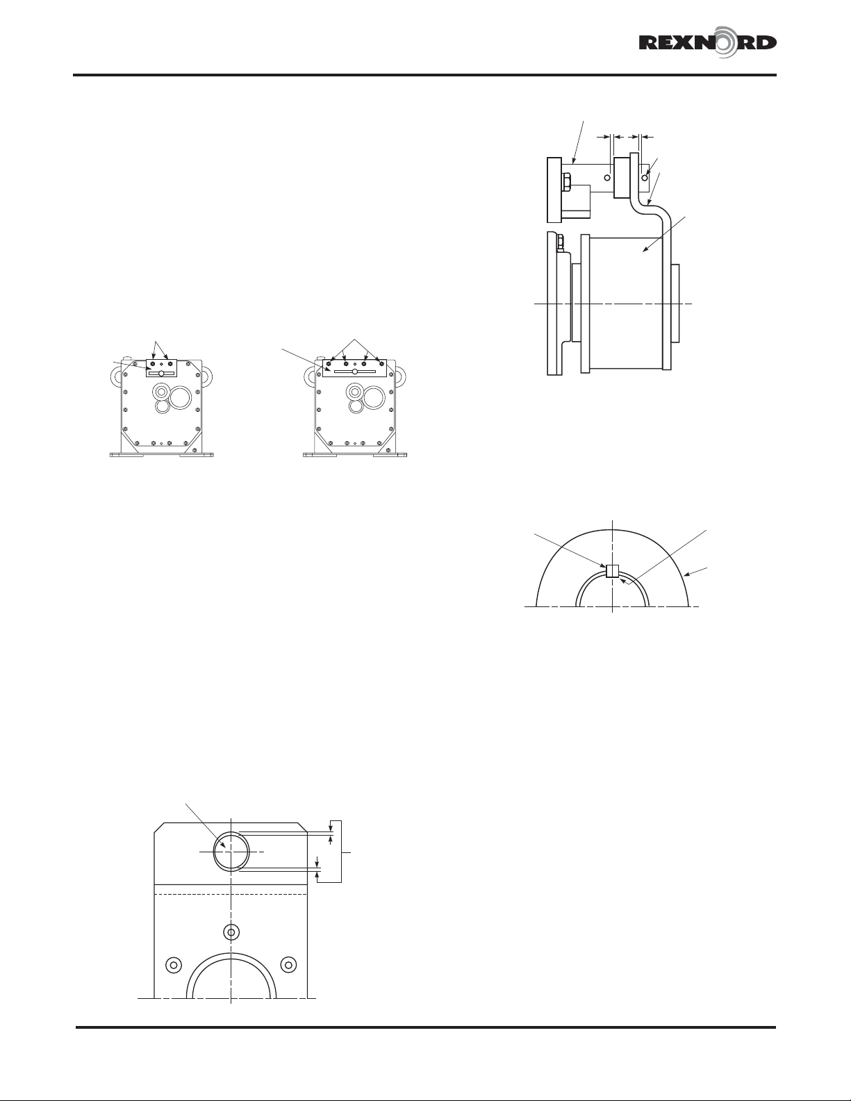
2. Install anchor bracket if necessary by removing the
appropriate high speed head fasteners to allow anchor
bracket to be centered above the high speed shaft (see
Figures1&2).Mount anchor bracket and insert the longer
fasteners and lock washers that were supplied with the
backstop kit. Tighten fasteners to values shown in Table 1.
3. Clean the backstop bore and the shaft on which the
backstop will be mounted. Make sure the short key is clean
and completely seated in the shaft.
4. Align the hub keyway with the shaft key and slide backstop
onto shaft and anchor bracket torque arm pin. The
backstop must slip onto shaft. DO NOT hammer backstop
onto shaft. There should be clearance between the
backstop anchor lug and torque arm pin as shown in
Figure 3. Position the backstop axially to allow clearance
for the extreme float limits of the shaft, Figure 4.
5. Install spring pins to hold backstop onto torque arm pin.
6. Check free, or overrunning, and locked rotation of
backstop. If satisfactory, stake key (inch series) to through
hardened shaft, Figure 5, or use an anaerobic thread
sealant such as Loctite 242 if shaft is carburized.
Installation — Drives with Shaft Fans
CAUTION: Refer to direction of rotation arrow on backstop.
Before installation make sure that the direction of rotation is
correct. To change the backstop over running direction, rotate
the backstop 180° end for end on shaft. For some
backstop/drive combinations, it will be necessary to have the
torque arm mounted on the outside of the backstop due to
interference with the anchor bracket. Follow specific instructions
found in Manual 568-810 shipped with the backstop. Check
backstop size on nameplate and make certain it is correct.
1. If installing external backstop on drive not previously
supplied with a backstop, a special - long high speed shaft
is required. Refer to drive assembly/disassembly
instructions for installation of high speed shaft.
2. Install anchor bracket if necessary by removing the
appropriate high speed head fasteners as shown in Figures
6 & 7. Mount anchor bracket and insert the longer
fasteners and lock washers that were supplied with the
backstop kit. Tighten fasteners to torque values shown in
Table 2.
WARNING:To meet OSHA requirements, double
reduction drives require a shaft sleeve between the fan
guard and backstop (see Figure 8).
Rexnord Industries, LLC, Gear Group318-814
3001 W. Canal St., Zip 53208-4200, Milwaukee, WI USA Telephone: 414-342-3131December 2006
External Backstop Installation •Falk™ UltraMax®Gear Drives
(Page 2 of 3) Type F •Sizes 2100 thru 2130
TORQUE
ARM
PIN
CLEARANCE
FIGURE 3
4-FASTENERS
ANCHOR
BRACKET
ANCHOR
BRACKET
2-FASTENERS
CLEARANCE
ANCHOR BRACKET
SPRING PINS
TORQUE ARM
PRT
BACKSTOP
FIGURE 4
FIGURE 1
Sizes 2100- 2130
with #20 PRT Backstops
without shaft fans
FIGURE 2
Sizes 2100- 2130 with
#60 or 65 PRT Backstops
without shaft fans
STAKE
KEY
BACKSTOP
KEY
FIGURE 5


