manuals.online logo
Brands
  1. Home
  2. •
  3. Brands
  4. •
  5. Rexnord
  6. •
  7. DC Drive
  8. •
  9. Rexnord Falk Quadrive A Guide

Rexnord Falk Quadrive A Guide

Instructions
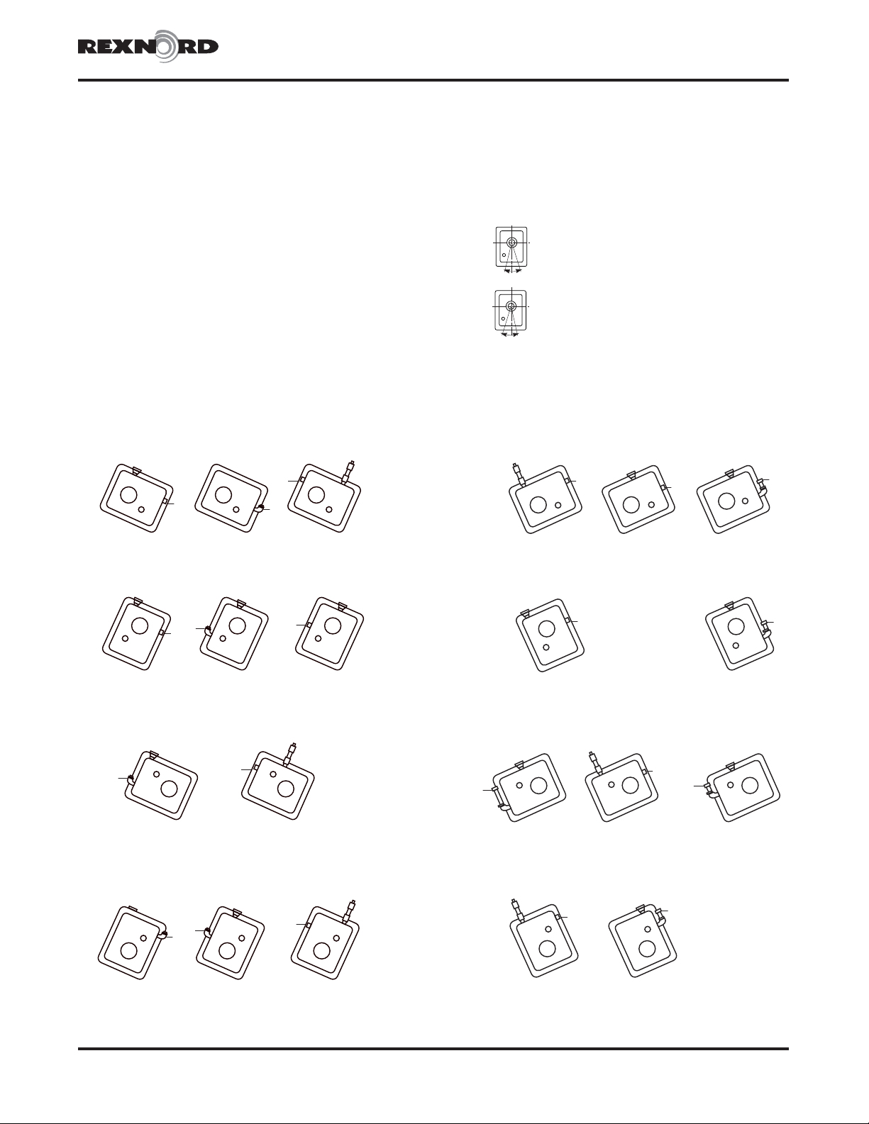
For non-standard mountings, modify drives as illustrated
below and on Page 2 to assure satisfactory lubrication. For
applications that exceed the limits shown, drives that are both
rotated AND tilted and drives with backstops, consult Factory.
CAUTION: Inadequate lubrication will cause damage.
When replacing a pipe plug (P) with a street elbow (E), insert
the plug in the elbow (E/P). When replacing a pipe plug (P)
with a street elbow (E), pipe nipple (N) and a pipe cap (C),
discard the pipe plug. Kits consist of parts for an oil expansion
chamber. Pipe fittings and kits tabulated on Page 2are
available from Rexnord. Pipe fittings may also be purchased
locally. Use galvanized pipe fittings.
Remove all pipe plugs and coat them and the added parts, with
Permatex #3 or equivalent to prevent leakage. Install parts as
illustrated to suit the mounting position. The air vent must be in
the top of the drive or in the kit standpipe. Fill drives with oil to
the level indicated by the letter “L” in the following drawings.
Rexnord Industries, LLC, Gear Group 378-124
3001 W. Canal St., Milwaukee, WI 53208-4200 USA Telephone: 414-342-3131 June 2006
Fax: 414-937-4359 e-mail: [email protected] web: www.rexnord.com Supersedes 8-98
Falk™ Quadrive®Shaft Mtd. Drives Model A •Non-Std. Mounting Installation
Sizes 5107-5315 (Page 1 of 2)
LLL
LL
L
LL
L
L
L
LL
L
LL
L
L
LLL
5107 = STD 5115 = .375 E/P 5203 & 5207 = KIT 0786775
5215 thru 5315 = KIT 0786776
5107 = STD 5115 = .375 E/P 5203 thru 5315 = STD
5107 = 5-12° STD
5107 = 13-20° .375 E/P
5115 = .375 E/P
5203 & 5207 = KIT 0786775
5215 thru 5315 = KIT 0786776
5107 = .375 E/P 5115 = .375 E/P 5203 & 5207 = KIT 0786775
5215 thru 5315 = KIT 0786776
5107 = KIT 0738540 5115 = STD 5203 = .375 E/C & .375 X 1.00N
5207 = .375 E/C & .375 X 2.00N
5215 = .500 E/C & .500 X 2.00N
5307 = .500 E/C & .500 X 2.50N
5315 = .500 E/C & .500 X 2.50N
5107 & 5115 = STD 5203 = .375 E/C & .375 X 1.00N
5207 = .375 E/C & .375 X 1.50N
5215 = .500 E/C & .500 X 1.12N
5307 & 5315 = .500 E/C & .500 X 2.00N
5107 = .375 E/C &
.375 X 3.00N 5115 = KIT 0786775 5203 = .375 E/C & .375 X 1.00N 1.50N
5207 = .375 E/C & .375 X 1.00N 1.50N
5215 = .500 E/C & .500 X 1.12N 1.50N
5307 = .500 E/C & .500 X 1.50N 2.00N
5315 = .500 E/C & .500 X 1.50N 2.00N
5107 & 5115 = KIT 0738540 5203 = .375 E/C & .375 X 1.50N
5207 = .375 E/C & .375 X 2.00N
5215 = .500 E/C & .500 X 2.00N
5307 = .500 E/C & .500 X 2.50N
5315 = .500 E/C & .500 X 2.50N
3 O’Clock — CW Rotation
6 O’Clock — CW Rotation
9 O’Clock — CW Rotation
12 O’Clock — CW Rotation
3 O’Clock — CCW Rotation
6 O’Clock — CCW Rotation
9 O’Clock — CCW Rotation
12 O’Clock — CCW Rotation
5 to 20° CW Rotation – Sizes 5107 & 5115
10 to 20° CW Rotation – Sizes 5203 thru 5315
5 to 20° CCW Rotation – Sizes 5203 thru 5315
10 to 20° CCW Rotation – Sizes 5107 & 5115
Standard Drive Mounting Limits
The standard drive rotation limits from the
basic 3, 6,9&12o’clock mounting
positions are shown at left. For higher limits,
follow the instructions at the left and the
drawings below. (6 o’clock illustrated)
CODE
B — Bushing N — Nipple
C — Cap P — Pipe Plug
E — Street Elbow STD — No Modifications
L — Oil Level
Horizontal Drive Modifications 20° Max. Drive Rotation
10
MAX.
°
5°
MAX.
ROTATION
(4107 & 4115)
5°
MAX.
10°
MAX.
(4203 THRU 4315)
5-15° 16-20°
Modifications for Non-Standard Mounting Positions
Non-Std. Mounting Installation •Falk™ Quadrive®Shaft Mtd. Drives Model A
(Page 2 of 2) Sizes 5107-5315
Rexnord Industries, LLC, Gear Group378-124
3001 W. Canal St., Milwaukee, WI 53208-4200 USA Telephone: 414-342-3131June 2006
Fax: 414-937-4359 e-mail: [email protected] web: www.rexnord.comSupersedes 8-94
L
L
L
L
L
L
*
*
L
*
L
*
H.S. Shaft Inclined 20 to 30° Up H.S. Shaft Inclined 5 to 30° Down
3 O’Clock H.S.S. Up 3 O’Clock H.S.S. Down
5107 THRU 5315 = STD
5107 THRU 5307 = STD
5315 = KIT 0786776
5107 THRU 5315 = STD
5107 = 5-25° .375 E/P
5107 = 26-30° .375 E/C, .375 X 1.00N & KIT 0786775
5115 = 5-20° .375 E/C & .375 X 1.00N
5115 = 21-30° .375 E/C, .375 X 2.00N & KIT 0786775
5203 = 5-30° .375 E/C & .375 X 1.50N
5207 = 5-15° .375 E/P
5207 = 16-30° .375 E/C & .375 X 2.00N
5215 = 5-30° .500 E/C & .500 X 2.50N
5307 = 5-30° .500 E/C & .500 X 2.50N
5315 = 5-30° .500 E/C & .500 X 2.50N
5107 = .375 E/P
5115 = .375 E/C & .375 X 2.00N
5203 = .375 E/C & .375 X 1.50N
5207 = .375 E/C & .375 X 2.00N
5215 = .500 E/C & .500 X 2.50N
5307 = .500 E/C & .500 X 2.50N
5315 = .500 E/C & .500 X 2.50N
5107 = 5-15° STD
5107 = 16-30° .375 E/P & KIT 0786775
5115 = 5-15° .375 E/P
5115 = 16-30° .375 E/C, .375 X 2.00N & KIT 0786775
5203 = 5-20° .375 E/P
5203 = 21-30° .375 E/C, .375 X 1.50N & KIT 0786775
5207 = 5-20° .375 E/C
5207 = 21-30° .375 E/C, .375 X 2.00N & KIT 0786775
5215 = 5-15° .500 E/P
5215 = 16-30° .500 E/C, .500 X 2.00N & KIT 0786776
5307 = 5-20° .500 E/P
5307 = 21-30° .500 E/C, .500 X 2.00N & KIT 0738471
5315 = 5-30° .500 E/C, .500 X 4.00N & KIT 0738471
5107 = 5-15° .375 E/P
5107 = 16-30° .375 E/C, .375 X 1.00N & KIT 0786775
5115 = 5-15° .375 E/P
5115 = 16-30° .375 E/C, .375 X 2.00N & KIT 0786775
5203 = 5-30° .375 E/C & .375 X 1.50N
5207 = 5-30° .375 E/C & .375 X 2.00N
5215 = 5-30° .500 E/C & .500 X 2.50N
5307 & 5315= 5-30° .500 E/C & .500 X 2.50N
QThis oil level applies when only a street elbow with a pipe plug is used.
6 O’Clock H.S.S. Up
9 O’Clock H.S.S. Up
12 O’Clock H.S.S. Up
6 O’Clock H.S.S. Down
9 O’Clock H.S.S. Down
12 O’Clock H.S.S. Down
Standard Drive Mounting
Limits
The standard drive incline limits from the
basic 3, 6,9&12o’clock mounting
positions are shown at left. For higher limits,
follow the instructions on Page 1 and the
drawings below. (6 o’clock illustrated)
CODE
C — Cap N — Nipple
E — Street Elbow P — Pipe Plug
L — Oil Level STD — No Modifications
Horizontal Drive Modifications for Inclined H.S. Shaft
Standard Pipe Fittings H— Inches
.375-18 NPT Falk No. .500-14 NPT Falk No.
.375 Street Elbow 0915252 .500 Street Elbow 0915251
.375 Cap 0914802 .500 Cap 0914803
.375 x 1 Nipple 0915724 .500 x 1.12 Nipple 0915734
.375 x 1.5 Nipple 0915725 .500 x 1.5 Nipple 0915735
.375 x 2 Nipple 0915722 .500 x 2 Nipple 0915736
.375 x 3 Nipple 0915727 .500 x 2.5 Nipple 0915723
.500 x 3 Nipple 0915737
.500 x 4 Nipple 0915739
HKits: Falk Nos. 0786775 & 0786776...Oilexpansion chamber parts. All
pipe fittings are galvanized.
0° Incline down on
drives with backstop
in9or12o'clock
mounting position.
5 DOWN°
30 UP
(20° FOR
4315)
°
INCLINE
L — Always locate at high side plug.
KIT — Install at standard air vent location.

Other manuals for Falk Quadrive A

1

Other Rexnord DC Drive manuals

Rexnord Planetgear 7000 User manual

Rexnord

Rexnord Planetgear 7000 User manual

Rexnord Falk Drive One DH User manual

Rexnord

Rexnord Falk Drive One DH User manual

Rexnord Falk A User manual

Rexnord

Rexnord Falk A User manual

Rexnord Falk Quadrive A Series User manual

Rexnord

Rexnord Falk Quadrive A Series User manual

Rexnord Falk Quadrive A User manual

Rexnord

Rexnord Falk Quadrive A User manual

Rexnord Falk UltraMax Series User manual

Rexnord

Rexnord Falk UltraMax Series User manual

Rexnord Falk CT Series Installation guide

Rexnord

Rexnord Falk CT Series Installation guide

Rexnord Falk A Series User manual

Rexnord

Rexnord Falk A Series User manual

Rexnord Falk Drive One D Series User manual

Rexnord

Rexnord Falk Drive One D Series User manual

Rexnord Falk Ultramite UJ 302 Installation and operating instructions

Rexnord

Rexnord Falk Ultramite UJ 302 Installation and operating instructions

Rexnord Falk V-Class VR Instruction manual

Rexnord

Rexnord Falk V-Class VR Instruction manual

Popular DC Drive manuals by other brands

ABB ACH580 Series How to set up

ABB

ABB ACH580 Series How to set up

YASKAWA SI-EN3 installation manual

YASKAWA

YASKAWA SI-EN3 installation manual

Astraada DRV-28 Series Operation manual

Astraada

Astraada DRV-28 Series Operation manual

Inova MD310 Quick start manual

Inova

Inova MD310 Quick start manual

ABB ACS850 series Quick start up guide

ABB

ABB ACS850 series Quick start up guide

HP StorageWorks Ultrium 960 User's and service guide

HP

HP StorageWorks Ultrium 960 User's and service guide

Danfoss VLT AutomationDrive FC 300 Design guide

Danfoss

Danfoss VLT AutomationDrive FC 300 Design guide

TECHTOP TD20 Series product manual

TECHTOP

TECHTOP TD20 Series product manual

YASKAWA VS-616PS5 Series Quick start manual

YASKAWA

YASKAWA VS-616PS5 Series Quick start manual

ABB ACS880 Series user manual

ABB

ABB ACS880 Series user manual

Masterflex I/P Series quick start guide

Masterflex

Masterflex I/P Series quick start guide

Festo EMCA-EC-67 CO Series Brief instructions

Festo

Festo EMCA-EC-67 CO Series Brief instructions

Danfoss FCM 300 Series Quick setup

Danfoss

Danfoss FCM 300 Series Quick setup

Danfoss VLT 6000 HVAC Series Quick setup manual

Danfoss

Danfoss VLT 6000 HVAC Series Quick setup manual

IBM 9040-MR9 manual

IBM

IBM 9040-MR9 manual

KEBCO COMBIVERT F0 instruction manual

KEBCO

KEBCO COMBIVERT F0 instruction manual

Moeller DV6-320 installation instructions

Moeller

Moeller DV6-320 installation instructions

YASKAWA 1000 Series installation manual

YASKAWA

YASKAWA 1000 Series installation manual

manuals.online logo
manuals.online logoBrands
  • About & Mission
  • Contact us
  • Privacy Policy
  • Terms and Conditions

Copyright 2025 Manuals.Online. All Rights Reserved.