manuals.online logo
Brands
  1. Home
  2. •
  3. Brands
  4. •
  5. Reznor
  6. •
  7. Heater
  8. •
  9. Reznor CAUA User manual

Reznor CAUA User manual

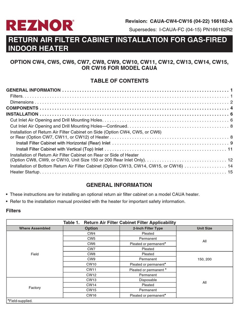
Revision: CAUA-IGN-CNTRL (03-22) 178435-A
IGNITION CONTROLLER REPLACEMENT KIT INSTALLATION
FOR GAS-FIRED INDOOR HEATER
Supersedes: CP-CAUA-IGN CNTRL (04-15) PN178435R6
MODEL CAUA
Table 1. Ignition Controller Replacement Kit (PN 258251) Components
Item No. Component Description PN (Quantity)
1
DSI control board Heat only (
UTEC #1097-211
)
195573 (1)
2
Wire assembly
9-pin, P1 on wiring diagram 257666 (1)
3 5-pin, P3 on wiring diagram 257675 (1)
4 24-inch, red, with one terminal 129869 (1)
5 Template Drill 257013 (1)
6 Ignition cable 18-inch 257665 (1)
7Terminal Quick connect, 1/4-inch, red 142860 (7)
8 Spade 1350 (1)
9 Wire nut Crimp 22573 (2)
10 Tie Cable 20913 (6)
11 Label NOTICE 203058 (1)
12
Wiring diagram 258250
(1)
⚠ DANGER ⚠
To ensure safe and proper operation, read and follow these installation instructions. Failure to do
so could result in property damage, personal injury, and/or death.
•These instructions are for replacing an obsolete ignition controller (RAM #3MC4-06, serial number code 76 or J/C
#G822KCC-5401D, serial number code 77) with an ignition controller (see Figure 1) replacement kit (PN 258251).
•Refer to the installation manual provided with the heater for important safety information.
•Refer to the replacement parts manual at www.reznorhvac.com for serial number information. All serial number
codes apply to original equipment only.
•Ensure that all components listed in Table 1 are available before beginning installation.
Figure 1. Replacement Ignition Controller
SPARK TRANSFORMER
123
456
789
9-Pin
Harness
Plug P1
1
2
3
4
5
5-Pin Harness
Plug P3
WIRE TERMINALS
2CAUA-IGN-CNTRL (03-22) 178435-A
INSTALLATION
Install the ignition controller replacement kit as follows. Item numbers in parentheses refer to Table 1.
1. Turn OFF gas and electric power.
2. Remove existing ignition controller:
a. Open control compartment and locate ignition controller.
b. Disconnect wiring and existing ignition cable from controller.
c. Remove four screws that secure controller and remove controller.
3. Install replacement ignition controller:
a. Position drill template (5), with painted side facing up, over mounting holes for ignition controller removed in
step 2. Justify holes for replacement controller toward bottom of panel.
b. Mark and drill four 3/16-inch holes.
c. Position DSI control board (1) so that spark transformer is located nearest to spark electrode on burner. Snap
control board into holes.
4. Install replacement ignition cable:
a. Remove existing ignition cable from spark electrode on burner.
b. Connect one end of replacement ignition cable (6) to spark electrode on burner and other end to spark
transformer (see Figure 1) on replacement DSI control board (1).
NOTE: Refer to Table 2 for terminal cross-reference between old and new ignition controllers.
Table 2. Terminal Cross-Reference
Existing Controller Replacement Controller
ACC EAC/BLO
24 VAC HOT SEC
Ground COM
LINE VAC HOT L1
CMB BLWR IND
5. Connect wiring in accordance with replacement wiring diagram label (12, see Figure 2):
a. Connect P3 5-pin wire assembly (3) to thermostat terminal strip as shown in Figure 1.
b. Connect P1 9-pin wire assembly (2) as shown in Figure 1. As necessary, shorten wires and install replacement
terminals (8).
c. Connect existing wires to DSI control board (1) wire terminals. If terminal on line voltage wire is 3/16 inch, cut
off terminal, strip wire, and install quick connect terminal (7). Connect line voltage wire to terminal L1.
d. Connect one end of 24-inch red wire assembly (4) to rollout switch located on burner box top. Connect other
end to high limit switch wire lead using wire nut (9).
e. Install cable ties (10) as necessary for routing and for excess wire length.
NOTE: To cover all applications, connections shown in Figure 2 are for single-stage (AG1) and
two-stage (AG2) controls and for both direct and belt drive motors. Make the connections that ap-
ply to the options on the unit being serviced.
6. Adhere wiring diagram label (12, see Figure 2) on left panel inside burner compartment.
3
CAUA-IGN-CNTRL (03-22) 178435-A
Figure 2. Wiring Diagram Label
7. Adhere NOTICE label (11, see Figure 3) below wiring diagram label installed in step 6.
3
3
TERMINAL
STRIP
THERMOST
AT
C
Y1
Y2
W1
W2
G
FAN RELAY
COIL
Y
7
R
RELAY COIL
7
CONTACTOR COIL
MOTOR
W
BK
BK
BK
FAN
RELAY CONTACTS
2
4
6
BK
R
W
G
Y
P3-4
P3-3
P3-2
R
G
W
C
Y1
Y2
W1
W2
P3-1
Y
P3-5
BR
G
FAN RELAY
COIL
Y
8 7
BR
7
R
C
BR
RELAY COIL
CUSTOMER'S COOL
7
W2
TERMINAL STRIP
THERMOSTAT
L1 L2
BK
W
24V
R
LINE VOLT Y
Y
R
BL
BK
PLUG PILOT OPENING
HONEYWELL TWO STAGE
REDUNDANT GAS VALV E
PILOT
PV
HI
HIGH
STG
LOW
STG
C
MV
R
BR
GAS VALVE
HONEYWELL
MV
MV BL
BR
ACB HEAT
ACB COOL BK
BK L2
CONTACTOR COIL
W
HEAT SPEED
CONTACTOR COIL
COOL SPEED
Y
BK
BK W
VENTER MOTOR
LED
DSI CONTROL
SW1
FAN OFF DELAY
TIME
90
120
160
180
OFF
OFF
ON
ON
ON
OFF
OFF
ON
12
S W 1
IND BK OR BL
NEUTRAL BK OR BR
(SEE NOTES)
LED
OKFLAME
GY
NEUTRAL
LIMIT
CONTROL
RR
R
P1-8
P1-3
BK OR BL
P1-2
P1-4
BL
BK
L1NEUTRAL
L1
SEC
ATO OR AT C
3.0 AMP
TEST
FUSE
FLAME
ROLLOUT SWITCH
ACB HEAT
ACB COOL
W
L1
L2
WL2
COM
1
O
BR
FLAME
ELECTRODE
FLAME
GROUND
P1-7
P1-9
PRESSURE SWITCH
Y
Y
P1-6
P1-5 W
3
SPARK GAP
SPARK
TRANSFORMER
BL
BK
BR
TRANSFORMER
40 VA
BR
BL
BK
R
BL
DOOR
SWITCH
BKBKBK
DSI BOARD
REPLACEMENT
Option AG2
Option AG1
BELT DRIVE
DIRECT DRIVE
NEUTRAL
L1
W W L2
BK
CAUA
WD #275047
RR
GREEN LED
FAST FLASH
1 FLASH
2 FLASH
3 FLASH
4 FLASH
STEADY OFF
LED FLASH CODES
NORMAL OPERATION CALL FOR HEAT
IN LOCKOUT FROM FAILED IGNITIONS OR FLAME
LOSSES
P1-8 TO P1-3 JUMPER OPEN CIRCUIT
PRESSURE SWITCH IS CLOSED BEFORE VENTER IS
ENERGIZED
INTERNAL CONTROL FAULT OR NO POWER
YELLOW LED
FLAME SENSEDSTEADY ON
SLOW FLASHWEAK FLAME
UNDESIRED FLAME (VALVE OPEN & NO CALL FOR
HEAT)
FAST FLASH
PRESSURE SWITCH DOES NOT CLOSE WITHIN
30 SECONDS OF VENTER ENERGIZED
NORMAL OPERATION NO CALL FOR HEATSTEADY ON
Figure 3. NOTICE Label
8. Turn ON electric power and gas, start up heater, and check for proper operation.
NOTE: Refer to the installation manual at www.reznorhvac.com for operating sequence and
troubleshooting information.
NOTICE
BEFORE REPLACING CIRCUIT BOARD:
• Check Fuse on Circuit Board
• Check 24VAC Supply
• Check LED Flash Codes
Replacing circuit board will not correct
prob lems that are external to the board.
203058 Rev. 1
Specifications and illustrations subject to change without notice or incurring obligations.
Latest version of this manual is available at www.reznorhvac.com.
©2022 Nortek Global HVAC LLC, O’Fallon, MO. All rights reserved.
CAUA-IGN-CNTRL (03-22) 178435-A

Other manuals for CAUA

7

Other Reznor Heater manuals

Reznor OH User manual

Reznor

Reznor OH User manual
Reznor VSUTE series Installation instructions

Reznor

Reznor VSUTE series Installation instructions

Reznor LDAP Owner's manual

Reznor

Reznor LDAP Owner's manual

Reznor AirBloc AC Series User manual

Reznor

Reznor AirBloc AC Series User manual

Reznor CAUA Installation and operating instructions

Reznor

Reznor CAUA Installation and operating instructions

Reznor UDBP Guide

Reznor

Reznor UDBP Guide

Reznor OH Installation and operating instructions

Reznor

Reznor OH Installation and operating instructions

Reznor UDAP Guide

Reznor

Reznor UDAP Guide

Reznor RA 140 User manual

Reznor

Reznor RA 140 User manual

Reznor INFRA-REZ TR Manual

Reznor

Reznor INFRA-REZ TR Manual

Reznor UEZ User manual

Reznor

Reznor UEZ User manual
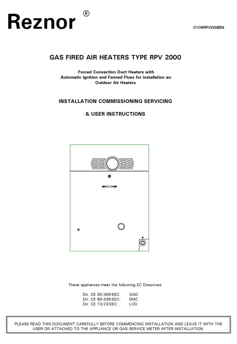
Reznor VPS User manual

Reznor

Reznor VPS User manual

Reznor CAUA User manual

Reznor

Reznor CAUA User manual

Reznor UBZ User manual

Reznor

Reznor UBZ User manual

Reznor EURO-C 4000 RJL Technical manual

Reznor

Reznor EURO-C 4000 RJL Technical manual

Reznor UDAP Guide

Reznor

Reznor UDAP Guide

Reznor CAUA Series User manual

Reznor

Reznor CAUA Series User manual
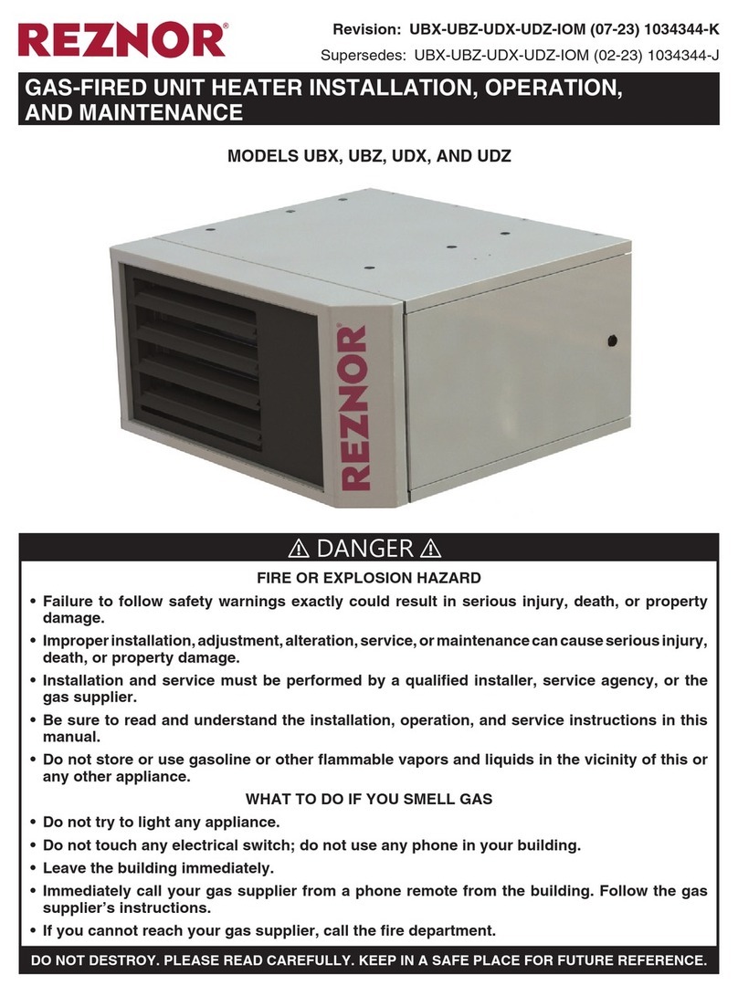
Reznor ACT03 User manual

Reznor

Reznor ACT03 User manual

Reznor CAUA User manual

Reznor

Reznor CAUA User manual

Reznor LDAP User manual

Reznor

Reznor LDAP User manual

Reznor CAUA User manual

Reznor

Reznor CAUA User manual

Reznor ULSA 035(EC) User manual

Reznor

Reznor ULSA 035(EC) User manual

Reznor EBHB User manual

Reznor

Reznor EBHB User manual

Reznor CAUA User manual

Reznor

Reznor CAUA User manual

Popular Heater manuals by other brands

Orbegozo CVT 3400 A instruction manual

Orbegozo

Orbegozo CVT 3400 A instruction manual

STIEBEL ELTRON CNS 100-1 Trend Operation and installation manual

STIEBEL ELTRON

STIEBEL ELTRON CNS 100-1 Trend Operation and installation manual

cecotec ReadyWarm 6250 Ceramic Sky Style instruction manual

cecotec

cecotec ReadyWarm 6250 Ceramic Sky Style instruction manual

Kermi BASIC 50 Series Instructions for installation and use

Kermi

Kermi BASIC 50 Series Instructions for installation and use

EOS 46.U Assembly and operating instruction

EOS

EOS 46.U Assembly and operating instruction

Farelek PTC 08 quick start guide

Farelek

Farelek PTC 08 quick start guide

Etherma SOLOMAGIC Z1 Installation and instruction manual

Etherma

Etherma SOLOMAGIC Z1 Installation and instruction manual

Sovelor GA100C User and Maintenance Book

Sovelor

Sovelor GA100C User and Maintenance Book

Jaga BRIZA 12 PLUG & PLAY manual

Jaga

Jaga BRIZA 12 PLUG & PLAY manual

Reece Kado Lussi MKII Operation and maintenance

Reece

Reece Kado Lussi MKII Operation and maintenance

Suntec Wellness KLIMATRONIC Heat Prime user manual

Suntec Wellness

Suntec Wellness KLIMATRONIC Heat Prime user manual

Scarlett SC-252 instruction manual

Scarlett

Scarlett SC-252 instruction manual

Designa DESE series instruction manual

Designa

Designa DESE series instruction manual

Lasko 5588 operating manual

Lasko

Lasko 5588 operating manual

Rinnai Energysaver EX38C manual

Rinnai

Rinnai Energysaver EX38C manual

EUROM PH2750 Instructions for use

EUROM

EUROM PH2750 Instructions for use

EUROM 34.200.0 instruction manual

EUROM

EUROM 34.200.0 instruction manual

Sveaverken Intelligent Technology SSHL175s user manual

Sveaverken Intelligent Technology

Sveaverken Intelligent Technology SSHL175s user manual

manuals.online logo
manuals.online logoBrands
  • About & Mission
  • Contact us
  • Privacy Policy
  • Terms and Conditions

Copyright 2025 Manuals.Online. All Rights Reserved.