manuals.online logo
Brands
  1. Home
  2. •
  3. Brands
  4. •
  5. RF SOLUTIONS
  6. •
  7. Transmitter
  8. •
  9. RF SOLUTIONS 202 Industrial Series User manual

RF SOLUTIONS 202 Industrial Series User manual

DS 202-1 ©2009 REG No 277 4001, Lewes, England. Page 1
200 Series Ind strial DIN RAIL
200 Series Ind strial DIN RAIL 200 Series Ind strial DIN RAIL
200 Series Ind strial DIN RAIL
•
Ind strial machine switching
Ind strial machine switchingInd strial machine switching
Ind strial machine switching
•
Home a tomation,
Home a tomation,Home a tomation,
Home a tomation,
•
Light switching,
Light switching,Light switching,
Light switching,
•
Flooding lighting,
Flooding lighting,Flooding lighting,
Flooding lighting,
•
P mps, Hoists,
P mps, Hoists,P mps, Hoists,
P mps, Hoists,
•
Loading Bins
Loading BinsLoading Bins
Loading Bins
•
Conveyors
ConveyorsConveyors
Conveyors
•
DIN Rail Switching systems
DIN Rail Switching systemsDIN Rail Switching systems
DIN Rail Switching systems
•
Battery powered transmitter option
Battery powered transmitter optionBattery powered transmitter option
Battery powered transmitter option
•
•
Up to 16 switch lines per receiver
Up to 16 switch lines per receiverUp to 16 switch lines per receiver
Up to 16 switch lines per receiver
•
Contact Ratings Up to 6KW
Contact Ratings Up to 6KWContact Ratings Up to 6KW
Contact Ratings Up to 6KW
•
Volt Free “Close contact” activation
Volt Free “Close contact” activationVolt Free “Close contact” activation
Volt Free “Close contact” activation
•
•
Range p to 300m
Range p to 300mRange p to 300m
Range p to 300m
•
Up to 8 channels per transmitter
Up to 8 channels per transmitterUp to 8 channels per transmitter
Up to 8 channels per transmitter
Sol tions Ltd
Sol tions LtdSol tions Ltd
Sol tions Ltd
202 Ind strial Series
202 Ind strial Series202 Ind strial Series
202 Ind strial Series
DS 202-1 ©2009 REG No 277 4001, Lewes, England. Page 2
Ordering
Ordering Ordering
Ordering
Receiver
ReceiverReceiver
Receiver
• 16 o tp ts
• The receiver learns p to 48 transmitters
• Momentary or latching o tp t options
• Flexible learn proced re allows “one to one”, “one to many “ and
“many to many” switching capability.
• LED indication to show active o tp ts.
• S pplied with b lkhead mo nting antenna
Relay Mod les
Relay Mod lesRelay Mod les
Relay Mod les
• S pplied with connection cables to receiver board
• 230
230 230
230 -
--
- 4 Ind strial level Relays
4 Ind strial level Relays 4 Ind strial level Relays
4 Ind strial level Relays
• 30A at 230V (5000W) per relay
• Change over contacts: Normally Open and Normally Closed
• 215
215 215
215 -
--
- 8 High q ality relays
8 High q ality relays 8 High q ality relays
8 High q ality relays
• 6A at 230V (1200w) per relay
• Change over contacts: Normally Open and Normally Closed
• 216
216 216
216 -
--
- 4 High q ality relays
4 High q ality relays 4 High q ality relays
4 High q ality relays
• 6A at 230V (1200w) per relay
• Change over contacts: Normally Open and Normally Closed
Part N mbers
Part N mbersPart N mbers
Part N mbers Description
DescriptionDescription
Description
Range
RangeRange
Range
(Metres)
(Metres)(Metres)
(Metres)
Freq
FreqFreq
Freq
(MHz)
(MHz)(MHz)
(MHz)
202-433F Transmitter 300 433.92
210-433F Receiver 300 433.92
230 / 215 / 230 Relay Boards N/A N/A
Transmitter
TransmitterTransmitter
Transmitter
• 8 No volt inp ts via screw terminal
• Simply connect a switch, relay or contactor via the screw terminals
and close the contact to send a transmission.
• On board battery with p to 3 years life span (back- p life)
• External inp t for 9-24Vdc if req ired
• A to Transmit feat re to ens re reliability
• Range p to 300m
• S pplied with b lkhead mo nting antenna
202 Ind strial Series
202 Ind strial Series202 Ind strial Series
202 Ind strial Series
DS 202-1 ©2009 REG No 277 4001, Lewes, England. Page 3
Installation g ide
Installation g ideInstallation g ide
Installation g ide
Transmitter set
Transmitter setTransmitter set
Transmitter set-
--
- p
pp
p
Power
PowerPower
Power
The 202 range of transmitters come with an on board lithi m battery (CR2032) and connection for an
external DC so rce if req ired.
External power in the range 9—24V DC may be applied via the screw terminal marked DC inp t (Fig 1.1)
For estimated battery life fig res see technical specifications page 7.
Wiring
WiringWiring
Wiring
Installation of the 202 transmitter range is simply a case of connecting the inp t screw terminals to yo r
chosen switch and if req ired connecting the power s pply
NOTE: Inp ts are volt free, DO NOT connect power to the inp ts.
Antenna Mo nting
Antenna Mo ntingAntenna Mo nting
Antenna Mo nting
The 202 comes with a BNC connector.
A to TX Link
A to TX LinkA to TX Link
A to TX Link
The 202 can be set to a tomatically transmit a “watchdog” signal, The A to Tx feat re sends the stat s
of all inp ts to all associated receivers at a random time between 5 and 10seconds. The receiver will drop
o t its signal fail relay within 20seconds of no comm nication.
The 202 has three A to TX options: Off, Defa lt and Forced.
• Off—Remove the j mper link from the pins; the A to TX is completely disabled.
• Defa lt—Cover pins 2-3 with the j mper link; the a to TX will only f nction when an external power
so rce is added. If external power fails the 202 will stop the a to Tx b t will otherwise operate normally.
• Forced—Cover pins 1-2; the a to TX with transmit at all times irrespective of the power so rce.
(CR2032 battery or external)
202 Ind strial Series
202 Ind strial Series202 Ind strial Series
202 Ind strial Series
DS 202-1 ©2009 REG No 277 4001, Lewes, England. Page 4
Installation g ide
Installation g ideInstallation g ide
Installation g ide—
——
—contin ed
contin edcontin ed
contin ed
Receiver set
Receiver setReceiver set
Receiver set-
--
- p
pp
p
Power
PowerPower
Power
The 210-433F receiver is powered by 12V or 24V DC, this is connected as shown below.
A reg lated power s pply capable of delivering at least 1 Amp is req ired (page).
For power cons mption fig res see Technical Specifications page
Wiring
WiringWiring
Wiring
Installation of the 210 receiver range req ires; connecting the power s pply as shown below and
connecting yo r chosen relay o tp t board(s).
202 Ind strial Series
202 Ind strial Series202 Ind strial Series
202 Ind strial Series
DS 202-1 ©2009 REG No 277 4001, Lewes, England. Page 5
Pairing Process
Pairing ProcessPairing Process
Pairing Process
Decide which inp t yo wish to operate which o tp t and follow the below process, bearing in mind
that LEDs on the 210-433F correspond directly to the relay o t n mber on a connected relay board:
1. Power the 210 receiver. On first se it will be in factory defa lt mode—all channel LEDs
flashing alternately on/off.
2. Power the 202 transmitter which yo want to pair. Send a signal, by closing a switch or
contact across any inp t. Ens re that the 210 receiver comes o t of factory defa lt and flashes
LED 3 briefly.
3. Once all LEDs are o t, press the 210 receiver’s learn b tton once briefly then (all LEDs will
flash on then go o t leaving only LED1 lit), tap the learn b tton repeatedly to scroll thro gh the
LEDs 1-16, stop at the desired LED n mber leaving that n mbered LED lit.
4. Momentarily close the contact or switch on the 202 transmitter inp t that yo wish to
pair to the selected 210 receiver o tp t.
5. The receiver’s o tp t LED sho ld flash to confirm that yo r chosen inp t is now paired to
the o tp t req ired.
6. Pairing is now complete for one channel, repeat for any other inp ts or o tp ts req ired.
Erasing the Receiver Memory
Erasing the Receiver MemoryErasing the Receiver Memory
Erasing the Receiver Memory
1. To completely erase the 210 receiver memory, press and hold the learn b tton
2. The learn LED (LED17) sho ld ill minate (Fig 1.2)
3. Hold the learn b tton for approximately 10seconds
4.
When the LED (LED17) exting ishes the memory is erased and the 210 receiver will ret rn to
factory defa lt mode.
Note: it is not possible to erase individ al transmitters or inp ts
.
A to Tx
A to TxA to Tx
A to Tx
When sing the 202-433F channel 16 becomes permanently active. It will t rn off if an A to Tx signal
form the 202-433F fails to get thro gh or if external power s pply fails on the 202-433F Transmit-
ter.
AUTO TX fail on power s pply fail can be disabled by switching the AUTO TX j mper link on the 202-
433F to the FORCE position.
NOTE:
NOTE: NOTE:
NOTE: The A to TX Channel does not need to be paired. If another pairing is made on this channel ena-
bling the A to Tx feat re wo ld override it.
202 Ind strial Series
202 Ind strial Series202 Ind strial Series
202 Ind strial Series
DS 202-1 ©2009 REG No 277 4001, Lewes, England. Page 6
Relay Mod le Set
Relay Mod le SetRelay Mod le Set
Relay Mod le Set-
--
- p
pp
p
Power
PowerPower
Power
Relay mod les are powered by the 210 Receiver and req ire no external s pply.
Connecting to a 210 receiver
Connecting to a 210 receiverConnecting to a 210 receiver
Connecting to a 210 receiver
The Relay boards pl g into the 210 receiver sing the connectors indicated below and on the previo s page.
Wiring
WiringWiring
Wiring
3 different relay mod les are available for se with a 210 Receiver, these all work in the same manner; oper-
ating a changeover contact the example below shows a 215 relay board.
202 Ind strial Series
202 Ind strial Series202 Ind strial Series
202 Ind strial Series
DS 202-1 ©2009 REG No 277 4001, Lewes, England. Page 7
Technical Specifications
Technical SpecificationsTechnical Specifications
Technical Specifications
202 Transmitters
202 Transmitters202 Transmitters
202 Transmitters
Part: 202
Part: 202Part: 202
Part: 202-
--
-433F
433F433F
433F
Dimensions:
Dimensions:Dimensions:
Dimensions:
Within DIN RAIL Bracket: 75 x 82mm. PCB Only: 75 x 72mm
Temperat re Range
Temperat re RangeTemperat re Range
Temperat re Range:
Storage -10 to +70
o
C. Operating: 0 to +55
o
C
Battery Life
Battery Life Battery Life
Battery Life -
--
- ESTIMATES
ESTIMATES ESTIMATES
ESTIMATES
Battery life fig res have been caref lly tested however, they may vary greatly depending on individ al in-
stallation conditions s ch as temperat re, and other factors.
*Shelf life of the battery will expire before it is depleted
Electrical Characteristics
Electrical CharacteristicsElectrical Characteristics
Electrical Characteristics Min
MinMin
Min Typical
TypicalTypical
Typical Max
MaxMax
Max Units
UnitsUnits
Units
S pply Voltage: 9-24V S pply 9 12 24 V
Antenna O tp t Lead Impedance 50 Ohms
Minim m inp t activation time to trigger transmission 50 ms
433MHz Version
433MHz Version433MHz Version
433MHz Version
S pply C rrent: Q iescent ~0 mA
S pply C rrent: Transmitting Data ~15 mA
Part N mber / description
Part N mber / descriptionPart N mber / description
Part N mber / description Battery
BatteryBattery
Battery
Capacity
CapacityCapacity
Capacity
Battery life
Battery life Battery life
Battery life
(A to Tx Forced
(A to Tx Forced (A to Tx Forced
(A to Tx Forced
enabled)
enabled)enabled)
enabled)
202-433F - On Board CR2032 220mAh 8 days
202-433F - 9V PP3 900mAh
4 Weeks
202-433F - 12V Lead Acid ~ Estimate ~ 6
Months
Battery Life
Battery LifeBattery Life
Battery Life
A to Tx off
A to Tx offA to Tx off
A to Tx off
20 switches p/day
20 switches p/day20 switches p/day
20 switches p/day
1 Year
Battery shelf life*
Battery shelf life*
202 Ind strial Series
202 Ind strial Series202 Ind strial Series
202 Ind strial Series
DS 202-1 ©2009 REG No 277 4001, Lewes, England. Page 8
Technical Specifications
Technical SpecificationsTechnical Specifications
Technical Specifications—
——
—contd
contdcontd
contd
210 Receivers
210 Receivers210 Receivers
210 Receivers
Part: 210
Part: 210Part: 210
Part: 210-
--
-433F
433F433F
433F
Dimensions:
Dimensions: Dimensions:
Dimensions:
Within DIN Rail: 138 x 82 mm (PCB: 133 x 72mm)
Temperat re Range:
Temperat re Range:Temperat re Range:
Temperat re Range:
Storage : -10 to +70o Celsi s. Operating: 0 to +55o Celsi s.
Electrical Characteristics
Electrical CharacteristicsElectrical Characteristics
Electrical Characteristics
Min
MinMin
Min
Typical
TypicalTypical
Typical
Max
MaxMax
Max
Units
UnitsUnits
Units
S pply Voltage: 12V S pply
10
12
16
V
S pply Voltage: 24V S pply
21
24
30
V
S pply C rrent : Q iescent
25
mA
Time from Tx Switch depressed to 210Rx o tp t
100
mSecs
Time from Tx Switch release to Decoder o tp t
200
mSecs
Switched o tp t Voltage (I o t = 1mA)
Logic Low
0
0.2
0.8
V
Logic High
3.5
3.8
5
V
C rrent Cons mption
C rrent Cons mptionC rrent Cons mption
C rrent Cons mption
433MHz Version
433MHz Version433MHz Version
433MHz Version
S pply C rrent: Q iescent
10
mA
All relays Active
All relays Active
mA
202 Ind strial Series
202 Ind strial Series202 Ind strial Series
202 Ind strial Series
DS 202-1 ©2009 REG No 277 4001, Lewes, England. Page 9
Technical Specifications
Technical SpecificationsTechnical Specifications
Technical Specifications–
––
– contd
contd contd
contd
Relay Mod les
Relay Mod lesRelay Mod les
Relay Mod les
215 Relay O tp t Mod le
215 Relay O tp t Mod le215 Relay O tp t Mod le
215 Relay O tp t Mod le
Part: 215
Part: 215Part: 215
Part: 215
8 relay o tp ts rated at 230Vac ,12A peak and 5A contin o s c rrent.
Dimensions: Within DIN Rail: 93 x 82 mm (PCB: 90 x 72mm)
Storage Temperat re: -10 to +70
o
Celsi s. Operating Temperat re: 0 to +55
o
Celsi s.
*The relay contacts in this nit are for f nctional se only and m st not be sed for isolation p rposes
*The relay contacts in this nit are for f nctional se only and m st not be sed for isolation p rposes*The relay contacts in this nit are for f nctional se only and m st not be sed for isolation p rposes
*The relay contacts in this nit are for f nctional se only and m st not be sed for isolation p rposes
216 Relay O tp t Mod le
216 Relay O tp t Mod le216 Relay O tp t Mod le
216 Relay O tp t Mod le
Part: 216
Part: 216Part: 216
Part: 216
4 relay o tp ts rated at 230Vac ,12A peak and 5A contin o s c rrent.
Dimensions: Within DIN Rail: 93 x 82 mm (PCB: 90 x 72mm)
Storage Temperat re: -10 to +70
o
Celsi s. Operating Temperat re: 0 to +55
o
Celsi s.
*The relay contacts in this nit are for f nctional se only and m st not be sed for isolation p rposes
*The relay contacts in this nit are for f nctional se only and m st not be sed for isolation p rposes*The relay contacts in this nit are for f nctional se only and m st not be sed for isolation p rposes
*The relay contacts in this nit are for f nctional se only and m st not be sed for isolation p rposes
230 Relay O tp t Mod le
230 Relay O tp t Mod le 230 Relay O tp t Mod le
230 Relay O tp t Mod le
Part: 230
Part: 230Part: 230
Part: 230
4 relay (type K7SFA12) o tp ts rated for p to 30A at 230Vac.
Dimensions: Within DIN Rail: 115 x 82 mm (PCB: 109 x 72mm)
Storage Temperat re: -10 to +70
o
Celsi s. Operating Temperat re: 0 to +55
o
Celsi s.
*The relay contacts in this nit are for f nctional se only and m st not be sed for isolation p rposes
*The relay contacts in this nit are for f nctional se only and m st not be sed for isolation p rposes*The relay contacts in this nit are for f nctional se only and m st not be sed for isolation p rposes
*The relay contacts in this nit are for f nctional se only and m st not be sed for isolation p rposes
Electrical Characteristics
Electrical CharacteristicsElectrical Characteristics
Electrical Characteristics
Min
MinMin
Min
Typical
TypicalTypical
Typical
Max
MaxMax
Max
Units
UnitsUnits
Units
S pply Voltage
From 210Rx mod le
Relay* o tp t Rating (type KB12) at 230Vac
5
12
A
Electrical Characteristics
Electrical CharacteristicsElectrical Characteristics
Electrical Characteristics
Min
MinMin
Min
Typical
TypicalTypical
Typical
Max
MaxMax
Max
Units
UnitsUnits
Units
S pply Voltage
From 210Rx mod le
Relay o tp t Rating @ 230Vac*
@ 12Vdc
30
A
20
A
Electrical Characteristics
Electrical CharacteristicsElectrical Characteristics
Electrical Characteristics
Min
MinMin
Min
Typical
TypicalTypical
Typical
Max
MaxMax
Max
Units
UnitsUnits
Units
S pply Voltage
From 210Rx mod le
Relay* o tp t Rating (type KB12) at 230Vac
5
12
A
202 Ind strial Series
202 Ind strial Series202 Ind strial Series
202 Ind strial Series
DS 202-1 ©2009 REG No 277 4001, Lewes, England. Page 10
Antenna and Range
Antenna and RangeAntenna and Range
Antenna and Range
Connecting an Antenna
Connecting an AntennaConnecting an Antenna
Connecting an Antenna
210-433F
The 210 Receiver has a 100mm flying lead cable (50ohm) with a panel mo nt BNC socket provided to mo nt
on an enclos re. This cable may be extended however please note that typically there is a 50% range red c-
tion with every 3metres of coax cable sed!
For increasing range performance a +3dB gain antenna is available. This is s pplied with wall mo nting
bracket and 2metres of coax cable, it pl gs in directly to the 210 Receiver BNC connector - Part N mber
MB450-BNC
202-433F
The 202-433F has a b lk head mo nting BNC connector for connecting the antenna (s pplied). This can also
be sed to connect an extension cable and remote antenna. It is important to note that typically there is a
50% range red ction with every 3metres of coax cable sed!
Range
RangeRange
Range
The antenna choice and position directly controls the system range. Keep it clear of other metal in the sys-
tem. The best position by far, is protr ding vertically from the top of the prod ct. This is often not desirable
for practical reasons and th s a compromise may be needed. Note that the space aro nd the antenna is as
important as the antenna itself. All radio systems are dependant on a radio signal being received thro gh
airspace.
The range q oted is the optimal in direct line of sight witho t obstacles and in good atmospheric conditions.
Range is affected by many things, for example local environmental conditions, atmospheric conditions, inter-
ference from other radio transmitters. For eval ating the local environment please see o r RF Meter
(DS006)
In very worse case applications the range q oted may be red ced below 30% of the optimal range stated.
Signal integrity
Signal integritySignal integrity
Signal integrity
In systems where many encoders are in close proximity there may be occasions when, d e to signal overlay
between encoders, it is diffic lt or impossible to g arantee system integrity. In s ch circ mstances it is the
responsibility of the installer to ens re that the system performance is adeq ate for the p rposes of the
installation.
Information availability
Information availabilityInformation availability
Information availability
All prod cts are s pplied with their relevant datasheets. These are also available for download from the web-
site or on req est from RF Sol tions Ltd.
202 Ind strial Series
202 Ind strial Series202 Ind strial Series
202 Ind strial Series
DS 202-1 ©2009 REG No 277 4001, Lewes, England. Page 11
R F Sol tions Ltd.,
R F Sol tions Ltd.,R F Sol tions Ltd.,
R F Sol tions Ltd.,
Unit 21, Cliffe Ind strial Estate,
Unit 21, Cliffe Ind strial Estate,Unit 21, Cliffe Ind strial Estate,
Unit 21, Cliffe Ind strial Estate,
Lewes, E. S ssex. BN8 6JL. England.
Lewes, E. S ssex. BN8 6JL. England.Lewes, E. S ssex. BN8 6JL. England.
Lewes, E. S ssex. BN8 6JL. England.
Email :
Email : Email :
Email : sales@rfsol tions.co. k
sales@rfsol tions.co. ksales@rfsol tions.co. k
sales@rfsol tions.co. k
http://www.rfsol tions.co. k
http://www.rfsol tions.co. khttp://www.rfsol tions.co. k
http://www.rfsol tions.co. k
Tel: +44 (0)1273 898 000
Tel: +44 (0)1273 898 000Tel: +44 (0)1273 898 000
Tel: +44 (0)1273 898 000
Fax: +44 (0)1273 480 661
Fax: +44 (0)1273 480 661Fax: +44 (0)1273 480 661
Fax: +44 (0)1273 480 661
Compatibility:
Compatibility:Compatibility:
Compatibility:
202
202202
202-
--
-433F
433F 433F
433F can also be sed with RF Sol tions prod ct:
HORNET-RX, 210-433F, RDF1
210
210210
210-
--
-433F
433F 433F
433F can be sed with transmitters:
HORNET-TXn, FIREFLY-TXn, 200-433F
210
210210
210-
--
-433F
433F 433F
433F can be sed with Relay boards:
215, 230, 216
Other prod cts in this series:
Other prod cts in this series:Other prod cts in this series:
Other prod cts in this series:
200
200200
200-
--
-525N
525N 525N
525N - Long Range Transmitter (1km)
210
210210
210-
--
-525N
525N 525N
525N - Long range Receiver (for se with the above)
200
200200
200-
--
-458F
458F 458F
458F - Very long range transmitter (6km)
210
210210
210-
--
-458F
458F 458F
458F - Very Long range Receiver (for se with the above)

This manual suits for next models

5

Other RF SOLUTIONS Transmitter manuals

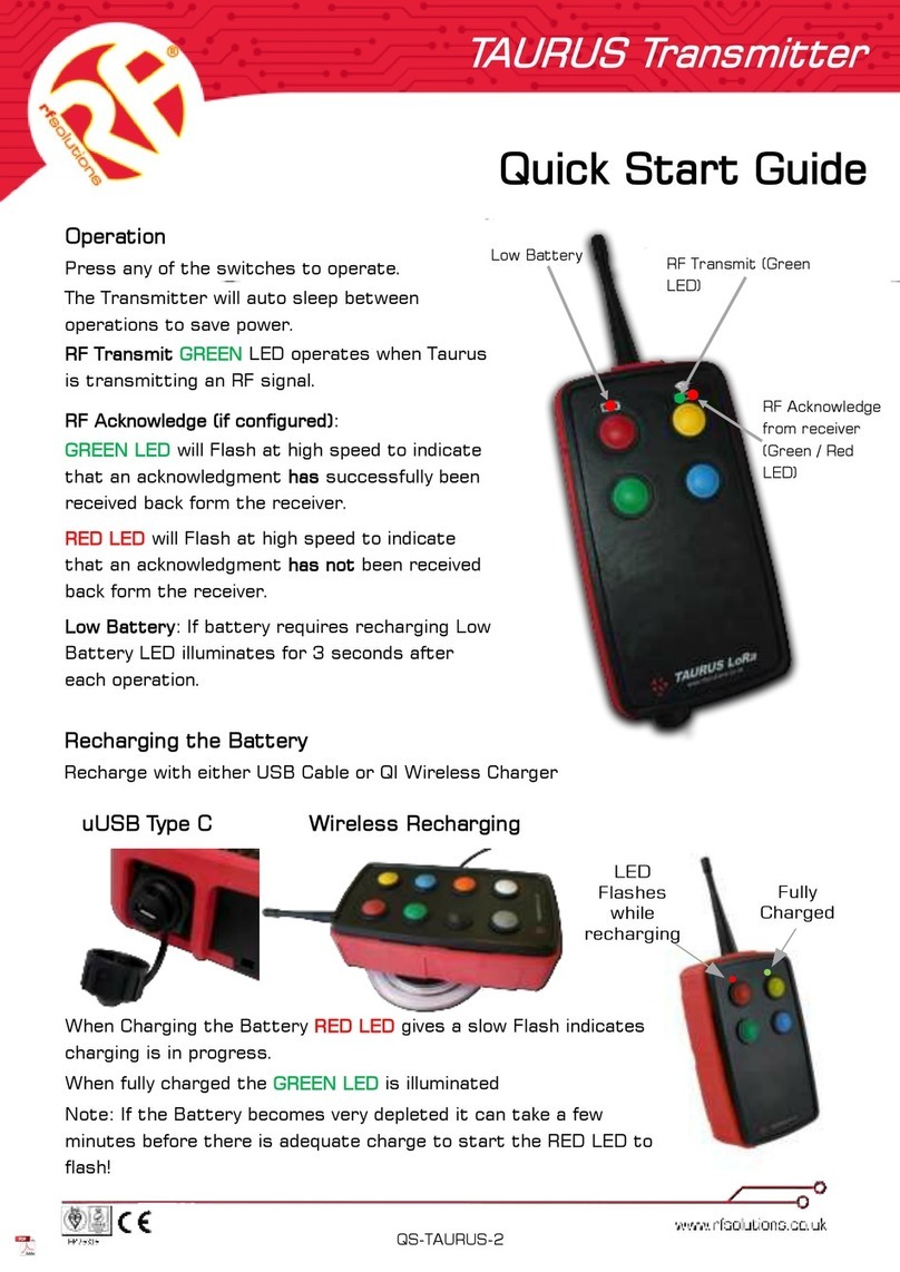
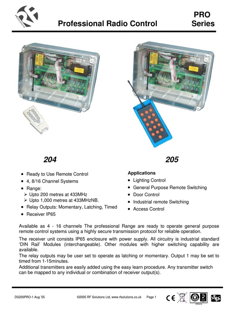
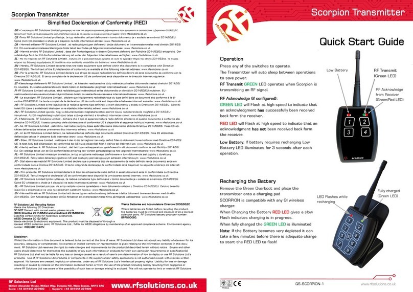
RF SOLUTIONS Scorpion User manual

RF SOLUTIONS

RF SOLUTIONS Scorpion User manual

RF SOLUTIONS TRAP User manual

RF SOLUTIONS

RF SOLUTIONS TRAP User manual

RF SOLUTIONS CARLTON-8T16 User manual

RF SOLUTIONS

RF SOLUTIONS CARLTON-8T16 User manual

RF SOLUTIONS TAURUS User manual

RF SOLUTIONS

RF SOLUTIONS TAURUS User manual

RF SOLUTIONS TAURUS Series User manual

RF SOLUTIONS

RF SOLUTIONS TAURUS Series User manual

RF SOLUTIONS PRO Series User manual

RF SOLUTIONS

RF SOLUTIONS PRO Series User manual

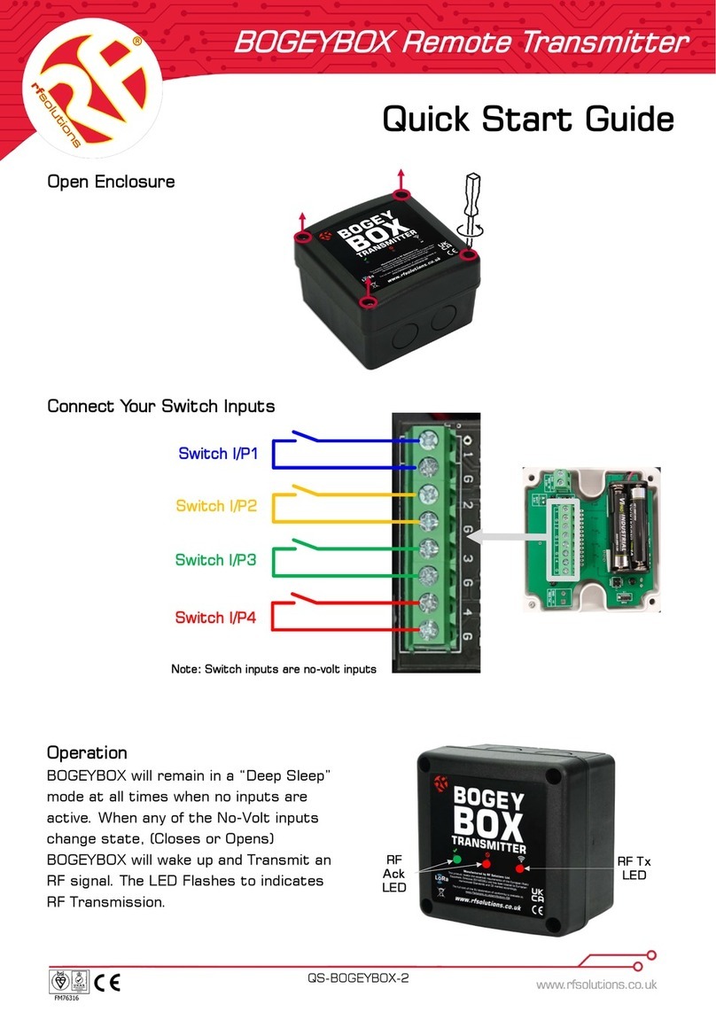
RF SOLUTIONS BOGEYBOX User manual

RF SOLUTIONS

RF SOLUTIONS BOGEYBOX User manual

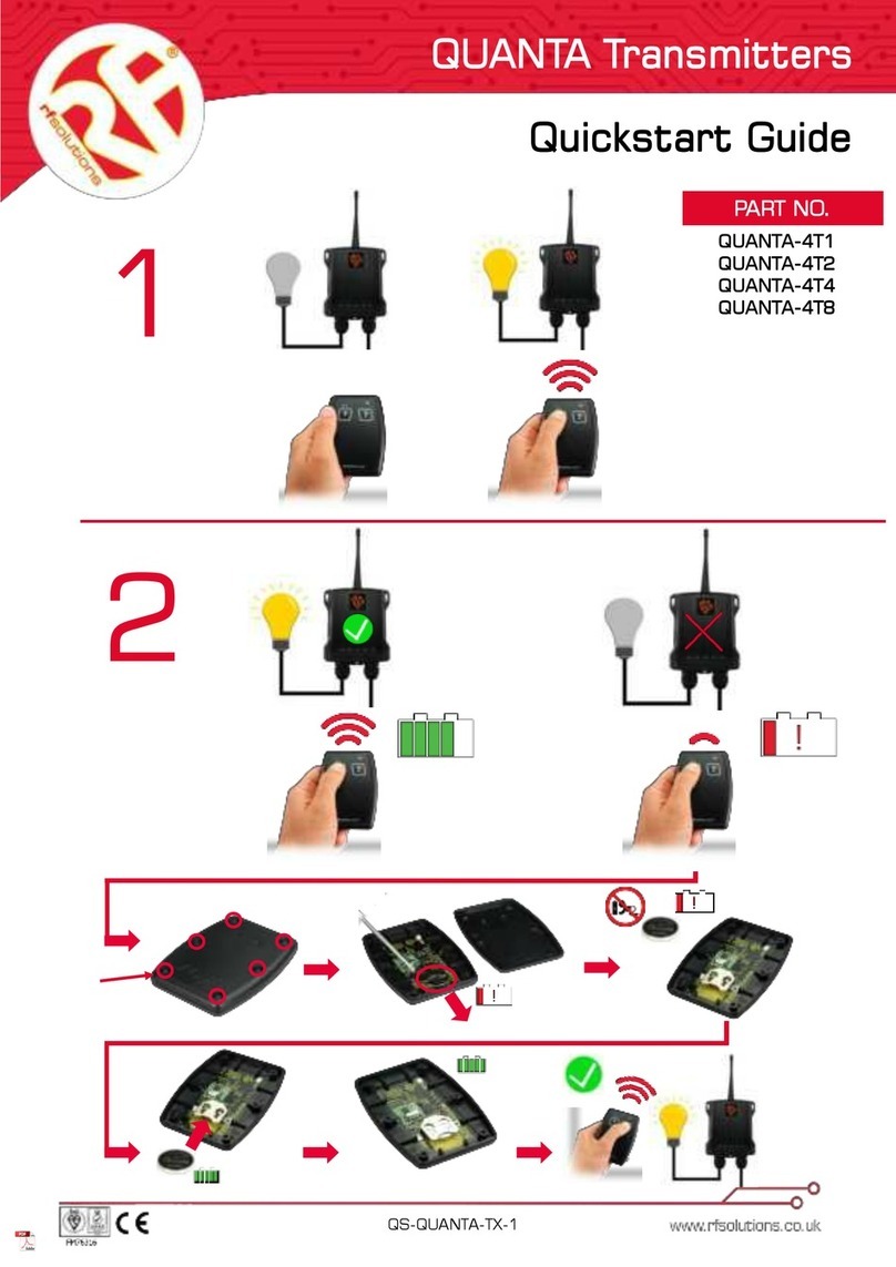
RF SOLUTIONS QUANTA QUANTA-4T1 User manual

RF SOLUTIONS

RF SOLUTIONS QUANTA QUANTA-4T1 User manual

RF SOLUTIONS SCORPION Series User manual

RF SOLUTIONS

RF SOLUTIONS SCORPION Series User manual

Popular Transmitter manuals by other brands

Tecfluid CP420L instruction manual

Tecfluid

Tecfluid CP420L instruction manual

Johnson VIKING 6N2 Assembly and operating instructions

Johnson

Johnson VIKING 6N2 Assembly and operating instructions

Abexo EGO32 user manual

Abexo

Abexo EGO32 user manual

AUREL TX 12 CH instruction manual

AUREL

AUREL TX 12 CH instruction manual

Telefunken TF-FMT19BT instruction manual

Telefunken

Telefunken TF-FMT19BT instruction manual

Extron electronics DTP2 T 201 D user guide

Extron electronics

Extron electronics DTP2 T 201 D user guide

Maverick MTX-244 instructions

Maverick

Maverick MTX-244 instructions

GPS GPS-FC-3T-BAS Installation, operation & maintenance manual

GPS

GPS GPS-FC-3T-BAS Installation, operation & maintenance manual

Tugicom TX25A user manual

Tugicom

Tugicom TX25A user manual

YOKOGAWA Dpharp EJA118N user manual

YOKOGAWA

YOKOGAWA Dpharp EJA118N user manual

Emerson Rosemount 3051SF Series quick start guide

Emerson

Emerson Rosemount 3051SF Series quick start guide

CircuitWerkes CW Broadcast ES Series Operating manual and user guide

CircuitWerkes

CircuitWerkes CW Broadcast ES Series Operating manual and user guide

ESX SXBLT2 owner's manual

ESX

ESX SXBLT2 owner's manual

Tecnocontrol SE193K Series user manual

Tecnocontrol

Tecnocontrol SE193K Series user manual

Magnetrol Pulsar R86 operating manual

Magnetrol

Magnetrol Pulsar R86 operating manual

Emerson Rosemount 1056 quick start guide

Emerson

Emerson Rosemount 1056 quick start guide

Dragon-RC DTS-1 instructions

Dragon-RC

Dragon-RC DTS-1 instructions

Grundig WST 864 user manual

Grundig

Grundig WST 864 user manual

manuals.online logo
manuals.online logoBrands
  • About & Mission
  • Contact us
  • Privacy Policy
  • Terms and Conditions

Copyright 2025 Manuals.Online. All Rights Reserved.