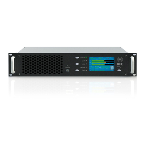
RFE 6KW DS Series User manual

SERVICE MANUAL
6KW DS SERIES

Document structure
This document contains all the technical information relating to the transmitters of Series DS.
In the first part we have all the technical specifications, followed by directions for the first
installation of the transmitter.
In the middle there is the explanation of the menu and functions of the transmitter, such as color
display touch screen.
There are explanatory photos of the various components of the transmitter.
Finally, follow the wiring diagrams and layouts.

Scope of the document
Purpose of this document is to provide a comprehensive description of the functionalities of the
DS TRANSMITTER and to provide operating information on the software elements of the system.
DS TRANSMITTER Service Manual provides software setup information.
Introduction
The transmitter DS is designed with all the latest technologies, such as high efficiency using the
latest generation LDMOS transistor and Power Supply. We used a modern interface and
performance using a color display with touch screen, with easy management software and easy to
use. Each transmitter DS is equipped with a LAN interface with the possibility of remote control
completely transmitter operation.
The transmitter DS is equipped with all audio inputs including Audio IP, for a complete audio
interface.

Preliminary Instructions
This equipment should only be operated, installed and maintened by trained or qualified personell
who know risks involved in working on electric and electronic circuits.
WARNING: Residual voltage may be present inside the equipment even when the ON/OFF
switch is set to Off. Before servicing the equipment, disconnect the power cord or switch off the
main power panel and make sure the safety earth connection is connected.
Some service situations may require inspecting the equipment with live circuits. Only trained
and qualified personnel may work on the equipment live and shall be assisted by a trained
person who shall keep ready to disconnect power supply at need.
RFE Broadcast S.r.l. shall not be liable for injury to persons or damage to property resulting from
improper use or operation by trained/untrained and qualified/unqualified persons.
WARNING: The equipment is not water resistant. Any water entering the enclosure might impair
proper operation. To prevent the risk of electrical shock or fire, do not expose this equipment to
rain, dripping or moisture.
Please observe local codes and fire prevention rules when installing and operating this equipment.
WARNING: This equipment contains exposed live parts involving an electrical shock hazard.
Always disconnect power supply before removing any covers or other parts of the equipment.
Ventilation slits and holes are provided to ensure reliable operation and prevent overheating; do
not obstruct or cover these slits. Do not obstruct the ventilation slits under any circumstances. The
product must not be incorporated in a rack unless adequate ventilation is provided or the
manufacturer’s instructions are followed closely.
WARNING: This equipment can radiate radiofrequency energy and, if not installed in compliance
with manual instructions and applicable regulations, may cause interference with radio
communications.
WARNING: This equipment is fitted with earth connections both in the power cord and for the
chassis. Make sure both are properly connected.
Operation of this equipment in a residential area may cause radio interference, in which case the
user may be required to take adequate measures.
The specifications and data contained here are provided for information only and are subject to
changes withot prior notice. RFE Broadcast S.r.l. disclaims all warrenties, express or implied. While
RFE Broadcast S.r.l. attempts to provide accurate information, it cannot accept responsibility or
liabily for any errors or inaccuracies in this manual, including the products and the software
described here. RFE Broadcast S.r.l. reserves the right to make changes to equipment design
and/or specifications and to this manual at any time without prior notice.
This product is a radio transmitter suitable for frequency modulation audio radio broadcasting. Its
operating frequencies are non-harmonised in designated countries. Before operating this

equipment, user must obtain a licence to use radio spectrum from the competent authority in the
designated user country. Operating frequency, transmitter power and other characteristics of the
transmission system are subject to restrictions as specified in the licence.

Technical Specifications
GENERAL
Power Output:6000W, adjustable from front panel.
RF Output Impedance: 50 ohm.
RF Output Connector: “7/8”.
Monitor RF: BNC connector.
VSWR: 1,5:1
Frequency Range: 87.5 ÷ 108.00 MHz, only for analog on request
66 ÷ 74 MHz ( OIRT), 76 ÷ 90 MHz (JPN) Programmable in 10 kHz steps.
Frequency Stability: ±1 ppm from -5 to 45°C.
External Reference: 10 MHz SMA connector back panel.
Type of Modulation: DS series analog synthesis, Option full digital
synthesis.
Off Lock Attenuation: ≥ -80 dBc.
Modulation Capability: ±150 KHz.
Limiter built in
Power Good Detector: adjustable from20÷90% of the power.
Audio Presence Detector: adjustable time from front panel.
External AGC: Automatic, with fine ADJ from front panel.
Modulation Mode: Mono, Stereo, Multiplex, SCA, RDS, Aux.
Preemphasis: Flat/50/75µs selectable from front panel.
Asynchronous AM S/N Ratio: -70 dB.
Synchronous AM S/N Ratio: -65 dB .
RF Harmonics: Exceeds EBU/CCIR/FCC requirements.
RF Spurious: Exceeds EBU/CCIR/FCC requirements.
MONAURAL OPERATION
Audio Input Impedance: 600 ohm - ≥10 Kohm balanced.
Audio Input Level: Digital -12 to +12 dBm, Analog -6 to +12 dBm
Input Connector: XLR female.
Audio Frequency Response: ±0.1 dB, 30 Hz to 15 KHz.
Total HarmonicDistortion + Noise: 0.01% @ 400 Hz.
Intermodulation Distortion: 0.01%, 1 KHz/1.3 KHz, 1:1 ratio.
Transient Intermodulation Distortion: 0.01% 2.96KHz square wave and
14 KHz sine wave.
Distortion: 0.01% 2.96KHz square wave and 14 KHz sine wave.
FM S/N Ratio: -80 dB rms detector,-75 dB below ±75 KHz deviation.
STEREO OPERATION
Audio Input Impedance: 600 ohm - ≥10 Kohm balanced.
Audio Input Level: Digital -12 to +12 dBm, Analog -6 to +12 dBm Input
Connector: XLR female.
Audio Frequency Response: ±0.1 dB, 30 Hz to 15 KHz.
Total Harmonic Distortion + Noise: 0.01% @ 400 Hz.
Intermodulation Distortion: 0.01%, 1 KHz/1.3 KHz, 1:1 ratio.
Transient Intermodulation Distortion: 0,01% 2.96KHz square wave and
14 KHz sine wave.
FM S/N Ratio: -80 dB rms detector, -75 dB below ±75 KHz deviation.
Stereo Separation: Digital 20 Hz ÷ 15 KHz ≥ -60dB, Analog -45 dB@30Hz
≥ -60dB@ Freq ≥ 100 Hz
Crosstalk attenuation: Digital Main to Sub -70 dB 30 Hz to 15 KHz,
Analog ≥ 45 dB@15kHz.
38 KHz Suppression: ≥ -85 dB.
Pilot Frequency: 19 KHz ± 1 Hz
Output Pilot: Digital 1 Vpp. BNC female, analog 2Vpp adjustable from
front panel
SIGNAL PROCESSING SECTION (only for Digital)
FM Carrier Generation: NCO-based synthesis
FM Modulation: Fully digital
Stereo Coder: Fully digital, integrated
Input Audio Limiter: Proprietary integrated Soft Limiter
Digital Signal Processing: Real-time internal24-bit digital processing
RDS Generator: Fully integrated
Monitoring Output Signals: Fully digitally generated
MULTIPLEX OPERATION
Composite Input Impedance: 2 Kohm unbalanced.
Composite Input Level: Digital -12 to +12 dBm, Analog -6 to +18 dBm
Input Connector: BNC female.
Composite Amplitude Response: ±0.1 dB, 30 Hz to 100 KHz.
Total Harmonic Distortion + Noise: 0.01% @ 400 Hz.
Intermodulation Distortion: 0.01%, 1 KHz/1.3 KHz, 1:1 ratio.
Transient Intermodulation Distortion: 0.01% 2.96KHz square wave and
14 KHz sine wave.
FM S/N Ratio: -80 dB rms detector, -75 dB below ±75 KHz deviation
AES/EBU OPERATION (optional for Analog)
Input Connector: XLR female, optical TOS-LINK.
Data Format: S/PDF,AES/EBU, IEC958, EIAJCP340/1201.
D/A Converter: 24 bit.
Sampling Frequency: from 32 to 96 KHz.
AUDIO IP (optional)
Lan: Audio IP and Web interface to control and configure
Transport protocol: RTP over UDP;
Protocols: RFE Codec: Alaw,OGG VORBIS, MP3, AAC
SHOUTCAST/ICECAST Codec : TX MP3, RX AAC, AAC+, MP3,
OGG(icecast 2.x)
SCA, RDS, AUX OPERATION
Input Impedance: ≥ 2 Kohm.
Input Level: -6 to +12 dBm.
Frequency Response: ±0.1 dB, 50 KHz to 100 KHz.
Input Connector: BNC female.
AUXILIARY CONNECTIONS
RS485: DB9 connector back panel.
CAN BUS (optional): DB9 connector back pane
Telemetry Interface: connector DB25 back panel.
LAN: RJ45 connector back panel
MPX OUT: connector BNC back panel.
OPTIONS
RDS/RBDS Programmable Coder via PC.
OIRT or JPN version.
SNMP
Audio Over IP
AES/EBU (only for Analog)
ELECTRICAL
AC Input Power: 90÷260 VAC 50/60 HZ single phase.
AC Apparent Power Consumption: 8500VA
Cos Ф> 0.98.
Cooling: Forced air.
Acoustic noise:< -56 dBa @ 1 meter.
ENVIRONMENTAL
Operating temperature: -5°C to +50°C.
Max Operating Altitude: 2000 mt.
Relative Humidity Range: 0 to 90%.
PHYSICAL DIMENSION
Mounting: Standard 19” chassis 4 U rack.
Size: W x 483 mm. D x 600 mm. H x 176 mm.
Weight: ~ 28Kg.
Software update
Core micro : Via Web

Installation and Use
General description
Transmitter DS series are FM transmitters manufactured by RFE Broadcast S.r.l. for audio radio
broadcasting in the 88 to 108 MHz band, featuring adjustable RF output up to 30 and 1000 W,
respectively, under 50 Ohm standard load.
The Trasmitters 6 kW DS series are designed to being contained into a rack box of 4 HE.
Unpacking
The package contains:
-1 DS TRANSMITTER
-1 CD-ROM with the User Manual
-1 Mains power cable
-Accessories and spare parts (screws/ front panel handles)
Features
State of the art performance
LCD color display with touch screen for easy setting and reading parameters
Extremely low distortion: THD, IMD & TIM (Transient Intermodulation Distortion) specified
Highest stereo performance: typ. 60 dB
L,/R, RDS / SCA, AUX, MPX, AES-EBU XLR & Optical, Audio IP
Six Memory (frequency, sensitivity, power, etc. ) which can be stored different setting.
Ready for N+1 system
Completely broadband
Remote control for telemetry LAN, RS485
RF amplifiers using the latest generation of semiconductors RF Power LDMOS
Automatic Power Control (APC) maintaining stable pre-set RF power 1.5:1 VSWR. Higher
VSWR value causes power reduction
Nominal RF output level 6000W. Continuously adjustable power output

Built-in RF harmonics filter and true wattmeter
High spectral purity
CCIR & FCC compilant
Front panel
The front panel has five LEDs that indicate the status of the transmitter, and are:
-ON LED green/yellow
-LOCK LED green
-REMOTE LED yellow
-INTERLOCK LED yellow
-FAULT LED red
There are also four keys for the functions of:
-ON
-REMOTE
-RESET
-BACK
These LEDs and its buttons, integrate the capabilities of the LCD, to understand the status of the
transmitter more clearly without access to the navigation menu.

Rear panel Transmitter
On the rear panel connectors are located as follows:
-Input Mains
-RF out 7/8 connector
-L/R audio input XLR connector
-MPX audio input BNC connector
-MPX audio output BNC connector
-AUX input BNC connector
-SCA/RDS input BNC connector
-19kHz in/out BNC connector
-AES/EBU input XLR/TOS-LINK connector (optional for analog)
-AUDIO IP input RJ45 connector
-10MHz input SMA connector (optional only for digital)
-1 PPS input SMA connector (optional only for digital)
-GSM Antenna SMA connector (optional)
-RDS/RS232 DB9 connector (optional)
-TLC/TLS DB25 connector
-RS485 DB9 connector
-LAN RJ45 connector

Rear panel Amplifier
On the rear panel connectors are located as follows:
-Input Mains
-RF out 7/8 connector
-RF in N connector
-GSM Antenna SMA connector (optional)
-TLC/TLS DB25 connector
-RS485 DB9 connector
-LAN RJ45 connector

DB25 (TLC/TLS) Rear connector
DB9 Rear connector

DB25 PinOut
1. GND
2. OUTPUT- Analog IPA
3. OUTPUT- Analog Reflected Power
4. INPUT- optoinsulated -External interlock (settable N.O. o N.C.)
5. INPUT- optoinsulated -Exciter ON (remote control)
6. INPUT- optoinsulated - memory M2
7. INPUT- optoinsulated - memory M4
8. INPUT- optoinsulated - memory M6
9. OUTPUT- Pin 2 rele contact –General alarm
10. OUTPUT- Pin 2 rele contact –Power & Audio good
11. OUTPUT- Pin 2 rele contact - ON/Stand-by
12. OUTPUT- Pin 2 rele contact - Local/Remote
13. OUTPUT +24VDC max 500mA
14. OUTPUT- Analog VPA
15. OUTPUT -Analog Forward Power
16. INPUT- optoinsulated –Alarm reset
17. INPUT- optoinsulated -Exciter OFF (remote control)
18. INPUT- optoinsulated - memory M1
19. INPUT- optoinsulated - memory M3
20. INPUT- optoinsulated - memory M5
21. INPUT- Analogico-External AGC (external directional coupler)
22. OUTPUT- Pin 1 rele contact –General Alarm
23. OUTPUT- Pin 1 rele contact –Power & Audio good
24. OUTPUT- Pin 1 rele contact - ON/Stand-by
25. OUTPUT- Pin 1 rele contact - Local/Remote
The functioning of the relays can be set from the front panel in normal open or normal closed.
DB9 PinOut
1. GND

2. 485 (optional Canbus)
3. INPUT- optoinsulated -Address 3
4. INPUT- optoinsulated - Address 1
5. OUTPUT +5VDC
6. 485 (optional Canbus)
7. GND
8. INPUT- optoinsulated - Address 2
9. INPUT- optoinsulated - Address 0
Quick Start Transmitter
Unpack the transmitter and inspect it for transport damage. Ensure that all connectors are in
perfect condition.
Connect the RF OUT of the trasmitter to the antenna cable or a dummy load capable of dissipating
exciter output power.
WARNING: Electric shock hazard! Never handle the RF output connector when the equipment is
powered on and no load is connected. Injury or death may result.
Ensure that the POWER switch on the rear panel is set to OFF.
Connect the mains power cable to the MAINS connector on the rear panel.
FIRST POWER-ON AND SETUP
At first power to make sure that the transmitter is connected to the antenna or a dummy load,
adequate power, connect the mains plug and turn on the transmitter. If you want to turn on the
transmitter with the lowest possible power, when the power to keep pressed the BACK
button simultaneously to the power on button.
Power-on transmitter display will show the following figure:

The display will show all the necessary information about the setting of the transmitter, such as:
-Frequency
-Forward Power
-Reflected Power
-L/R Modulation
-Deviation Modulation
-Limiter
-Input Mode
-RDS
-Input Impedance
-Preemphasis
-Modulation Mode
-Memory
-IP
-Mask
-Menu
Quick Start Amplifier
At first power to make sure that the amplifier is connected to the antenna or a dummy load,
adequate power, connect the mains plug and turn on the transmitter. If you want to turn on the
amplifier with the lowest possible power, when the power to keep pressed the BACK
button simultaneously to the power on button.
Power-on transmitter display will show the following figure:

The display will show all the necessary information about the setting of the transmitter, such as:
-Output Forward Power
-Output Reflected Power
-Input Forward Power
-IPA1; IPA2; IPA3
-VPA
-RF Temperature
-Menu
Menu Amplifier
Display and programming of the amplifier is through the LDC display touch screen. From the first
screen at power, as previously explained, can be accessed through the menu button to the
submenu of the Power, Setting, and Alarm.
Touching a symbol on the display is accessed directly from the menu chosen and you can
implement all the changes you want. Each menu is simple and intuitive without the need for any
manual so that all changes following what appears on the display. Following are the main screens
that allows the display.
In the settings menu you will find all the possible configurations of the date and time, external
interlock, LAN configuration, setting a general machine and all measures concerning the voltages
and currents in the transmitter.
MENU

POWER SETTING
DB25 SETTING
LAN CONFIGURATION

LOG EVENT
Menu Transmitter
Display and programming of the transmitter is through the LDC display touch screen. From the
first screen at power, as previously explained, can be accessed through the menu button to the
submenu of the Audio, Frequency, Power, Setting, Memories and Alarm.
Touching a symbol on the display is accessed directly from the menu chosen and you can
implement all the changes you want. Each menu is simple and intuitive without the need for any
manual so that all changes following what appears on the display. Following are the main screens
that allows the display.
That related to memories need an explanation, the transmitter can store six different settings in
six memories, these can be called either remotely or locally; This is used in systems n + 1 in the
case of transmitters reserve. The storing of data, frequency, power, etc. are possible with the
transmitter on the air, without interrupting transmission. When storing the display shows
"SETTING MEMORIES", at the end the display will show all the data chosen.
In the settings menu you will find all the possible configurations of the date and time, external
interlock, LAN configuration, setting a general machine and all measures concerning the voltages
and currents in the transmitter.

MAIN PAGE
MENU

POWER SETTING
FREQUENCY SETTING

AUDIO SETTING
AUDIO LEVEL SETTING
Table of contents
Other RFE Transmitter manuals