manuals.online logo
Brands
  1. Home
  2. •
  3. Brands
  4. •
  5. RGBlink
  6. •
  7. Extender
  8. •
  9. RGBlink MSP 217 Series User manual

RGBlink MSP 217 Series User manual

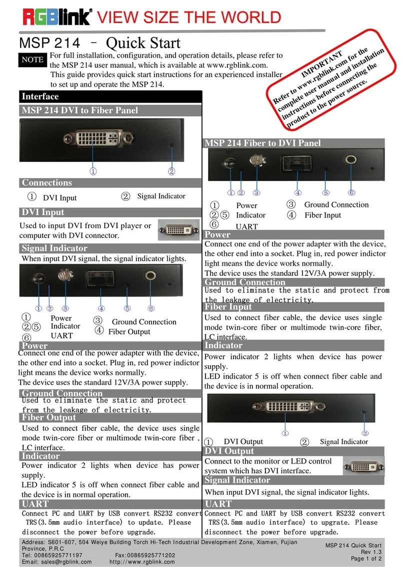
MSP 217 –Quick Start
MSP 217-TX SDI to Fiber Right Panel
Signal Indicator
Power Interface
Connection
MSP 217-RX Fiber to SDI Left Panel
14
Remote communication device control interface, used
to connect to the computer or console.
Power Interface
USB Interface
Interface
The device uses the standard 12V/1.5A power supply.
Signal Indicator
SDI Input Interface
SDI input interface,Can receive video signal from
HD player, and HD camera, connect interface 16 via
75 ohms impedance BNC port. Connect LED screens
via network cable.
Fiber Output Interface
1
1
VIEW SIZE THE WORLD
NOTE For full installation, configuration, and operation details, please refer to
the MSP 217 user manual, which is available at www.rgblink.com.
This guide provides quick start instructions for an experienced installer
to set up and operate the MSP 217.
Address: S603-604 Weiye Building Torch Hi-Tech Industrial Development Zone, Xiamen, Fujian Province, P.R.C
Tel: 00865925771197 Fax:00865925771202
Email: [email protected] http://www.rgblink.cn
MSP 217 Quick Start
Rev 1.0
Page 1 of 2
53
62
SDI Input Interface USB Interface
Power indicator 2 lights when device has power
supply.
LED indicator 4 is on when connect SDI cable and
the device is in normal Operation.
LED indicator 6 is on when connect USB cable and
the device is in normal Operation.
MSP 217-TX SDI to Fiber Left Panel
Connection
1 2Signal Indicator Fiber Output Interface
Signal Indicator
LED indicator 1 is on when connect fiber cable and
the device is in normal operation.
Used to connect fiber cable, the device uses single
mode one-core, LC interface.
Connection
2Signal Indicator Fiber Input Interface
Signal Indicator
LED indicator 1 is on when connect fiber cable and
the device is in normal operation.
Fiber Input Interface
Used to connect fiber cable, the device uses single
mode one-core, LC interface.
MSP 217-RX Fiber to SDI Right Panel
Connection
53
642Power Interface Signal Indicator
SDI Output Interface USB Interface
Power Interface
The device uses the standard 12V/1.5A power supply.
SDI Output Interface
USB Interface
Function Block Diagram
Operating Principle
MSP 217 SDI to Fiber
Address: S603-604 Weiye Building Torch Hi-Tech Industrial Development Zone, Xiamen, Fujian Province, P.R.C
Tel: 00865925771197 Fax:00865925771202
Email: [email protected] http://www.rgblink.cn
MSP 217 Quick Start
Rev 1.0
Page 2 of 2
Common Questions and Solution
Signal Indicator
Power indicator 2 lights when device has power supply.
LED indicator 4 is on when connect SDI cable and the
device is in normal Operation.
LED indicator 6 is on when connect USB cable and
the device is in normal Operation.
SDI output interface,Can receive video signal from
HD player, and HD camera, connect interface 16 via
75 ohms impedance BNC port. Connect LED
screens via network cable.
Remote communication device control interface,
used to connect to the computer or console.
Operation Manual
MSP 217 SDI to Fiber transmitter is connected to
media player or HD/SD SDI camera, etc. MSP 217
SDI to Fiber transmitter to power supply. In order to
avoid the damage of device, please use the standard
power adapter. Fiber interface is used to connect to
MSP 217 Fiber to SDI receiver.
MSP 217 Fiber to SDI
Function Block Diagram
Operating Principle
on MSP 217 SDI to Fiber transmitter with fiber cable,
and then connect the SDI interface on MSP 217 Fiber
to SDI panel to display device.In order to avoid
damaging the device, please use the standard power
adapter.
MSP 217 Fiber to SDI receiver is connected to
television (monitor) or other device which has SDI
interface
Connect the fiber interface to the other interface
Power indicator light is off or blinks
1. Check whether plug in the power cord, and has
power supply;
2. Check whether the power cable is connected, and
in good connection;
3. If above without problem, then the power indicator
is damaged.
Signal indicator light is off or blinks
1. Check whether connect the signal;
2. Check whether the input signal, input wire and output
wire are normal, the interfaces are in good connection;
3. If above without problem, then the signal indicator is
damaged.
Note: The indicator beside fiber interface is on when the
device is in normal operation. It will off or blink if the
fiber cable is in poor connection.
12V power interface poor contact
1. Check whether the power interface is in good
connection, if the interface is not tighten, screw it again.
2. Check whether any problem with adapter head,
replace it if there is any problem.
3. Check the power connector is loose, if so, please send
to processional personnel for repair.
This manual suits for next models

2

Other RGBlink Extender manuals

RGBlink MSP 215 User manual

RGBlink

RGBlink MSP 215 User manual

RGBlink MSP 215 User manual

RGBlink

RGBlink MSP 215 User manual

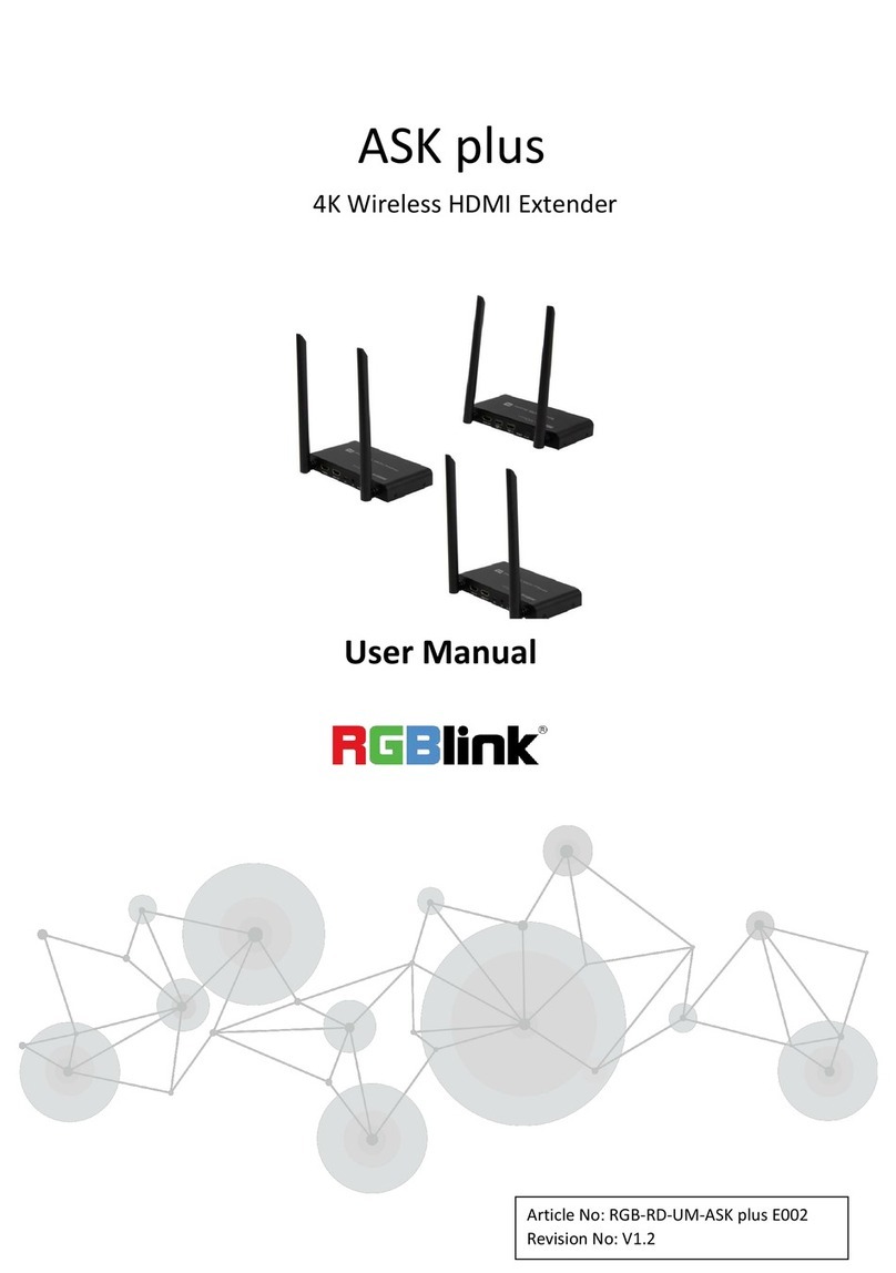
RGBlink ASK plus User manual

RGBlink

RGBlink ASK plus User manual

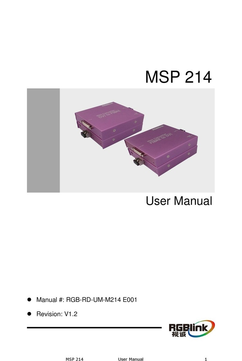
RGBlink MSP 214 User manual

RGBlink

RGBlink MSP 214 User manual

RGBlink MSP 315 User manual

RGBlink

RGBlink MSP 315 User manual

RGBlink MSP 227 User manual

RGBlink

RGBlink MSP 227 User manual

RGBlink MSP 214 User manual

RGBlink

RGBlink MSP 214 User manual

RGBlink MSP 318N User manual

RGBlink

RGBlink MSP 318N User manual

RGBlink MSP 318 User manual

RGBlink

RGBlink MSP 318 User manual

RGBlink MSP530 User manual

RGBlink

RGBlink MSP530 User manual

RGBlink MSP 225 User manual

RGBlink

RGBlink MSP 225 User manual

RGBlink MSP 214 User manual

RGBlink

RGBlink MSP 214 User manual

RGBlink MSP 226 User manual

RGBlink

RGBlink MSP 226 User manual

RGBlink ASK plus p2p User manual

RGBlink

RGBlink ASK plus p2p User manual

Popular Extender manuals by other brands

TP-Link RE230 Quick installation guide

TP-Link

TP-Link RE230 Quick installation guide

Garmin EX3800 user manual

Garmin

Garmin EX3800 user manual

Metrodata WCM5100 user manual

Metrodata

Metrodata WCM5100 user manual

Anritsu MN25131A Series Operation manual

Anritsu

Anritsu MN25131A Series Operation manual

MaxiiCopper Vi2300W installation manual

MaxiiCopper

MaxiiCopper Vi2300W installation manual

Huawei WS322 user guide

Huawei

Huawei WS322 user guide

KanexPro HDEXT50M Setup guide

KanexPro

KanexPro HDEXT50M Setup guide

TP-Link RE305 user guide

TP-Link

TP-Link RE305 user guide

StarTech.com ST121R instruction manual

StarTech.com

StarTech.com ST121R instruction manual

AV Access 4KEX70-L user manual

AV Access

AV Access 4KEX70-L user manual

VersiVision HD series user manual

VersiVision

VersiVision HD series user manual

EnGenius ERB9260 user manual

EnGenius

EnGenius ERB9260 user manual

Paradyne TNE1520-P installation instructions

Paradyne

Paradyne TNE1520-P installation instructions

Westermo Wolverine DDW-225 user guide

Westermo

Westermo Wolverine DDW-225 user guide

Extron electronics FOX II T DP Setup guide

Extron electronics

Extron electronics FOX II T DP Setup guide

atBox Technology InternetVue DT11-KIT user manual

atBox Technology

atBox Technology InternetVue DT11-KIT user manual

Allnet ALL-MC301P2WIRE-T Quick installation guide

Allnet

Allnet ALL-MC301P2WIRE-T Quick installation guide

Altronix AL642ULADA Application guide

Altronix

Altronix AL642ULADA Application guide

manuals.online logo
manuals.online logoBrands
  • About & Mission
  • Contact us
  • Privacy Policy
  • Terms and Conditions

Copyright 2025 Manuals.Online. All Rights Reserved.