WARNING:
USING DEFECTIVE WIRE ROPE CAN CAUSE EQUIPMENT DAMAGE, SERIOUS
PERSONAL INJURY, OR DEATH.
5.)Alwaysusesafetyfootwear,safetyglasses,and
6.)Wearheavyleathergloveswhenhandlingwire
4.)AllpersonnelshallbeprotectedbyOSHA
compliantfallprotectionwhereapplicable.
headprotectiondevices.
ofmovingparts.
hoistisbeingoperated.Keepallbodypartsclear
preventunathorizeduse.Neverassumeyouwill
findthehoistinthesameconditioninwhichyou
20.)Donotattempttomakeadjustmentswhilethe
21.)Atendofoperation,thehoistshouldbesecuredto
leftit.
22.)Donotweldorotherwisemodifythehoist.Such
23.)Onlytrainedpersonnelareauthorizedtomake
alterationsmayweakenthestructuralintegrityof
repairs.
thehoist.
62156789901
Donotclimbthetrack;usealadder.
hasstoppedcompletely.
16.)Keepoutfromunderaraisedload.Neverhoist
19.)Nopersonshallbeallowedtorideonthehoist.
17.)Neverstandin-linewiththeraisingorloweringof
theplatformateitherthetoporthebottomofthe
18.)Donotremovematerialfromtheplatformuntilit
10.)Donotoperatehoistwhenundertheinfluenceof
11.)Donotoperatehoistifbrakeropeiswet.
13.)NeverexceedtheRatedLoadCapacityof200lbs.
forPL-250hoist,or400poundsforthePL-400
14.)Iftheengineormotorfailsduringoperation,
releasecontrolleverstopreventloadfromfalling.
15.)Controlloadatalltimes.Avoidsuddenstops
hoist.TheRatedLoadCapacityisthemaximum
loadthatmusteverbeappliedtothehoist.
7.)Hoistingareaistobekeptclearofunathorized
personnelatalltimes.Placebarricadesorsecure
theareainsuchmannerthatiftherewerean
8.)Hoistingareaistobeclearofpowerlines.Consult
PowerCompanybeforeyouworknearpower
equipmentfailure,nopersonnelwouldbeinjured.
9.)FollowthePre-HoistingChecklistbeforeoperating.
overanopendoorway.
hoisttrack.
drugs,alcohol,ormedication.
12.)Secureloadbeforelifting.
andshockloads.
lines.
rope.
individualresponsibilities,personalprotective
PL-250/400HOISTSAFETYRULES:
operatingthishoist.Atrainedpersonisonewho
1.)Operatorsmustbethoroughlytrainedbefore
hasreadandthoroughlyunderstandsthe
instructionmanualandrelatedequipment
manualsand,throughtrainingandexperience,
hasshownknowledgeregardingsafeoperating
2.)Priortosettingupthehoisttheremustbeaplanof
actionoutliningtheworktobeaccomplished,
3.)Agoodlineofcommunicationmustbemaintained
betweenthehoistoperatorandroofcrew.
equipment,andmethodofcommunication.
procedures.
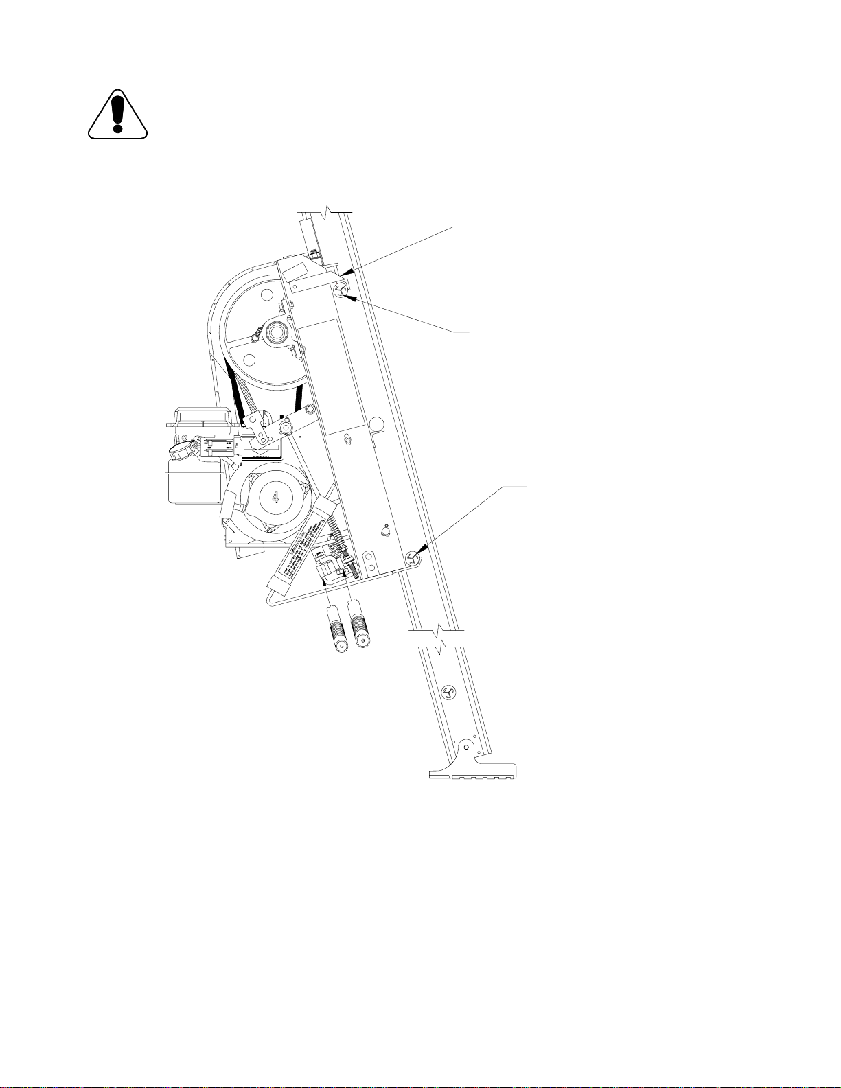
3RD CROSSTIE
CROSS TIE CLAMP
5TH CROSSTIE
Figure 3-1.
Classic Power Drive 250HG Installation on Pro track
5