6
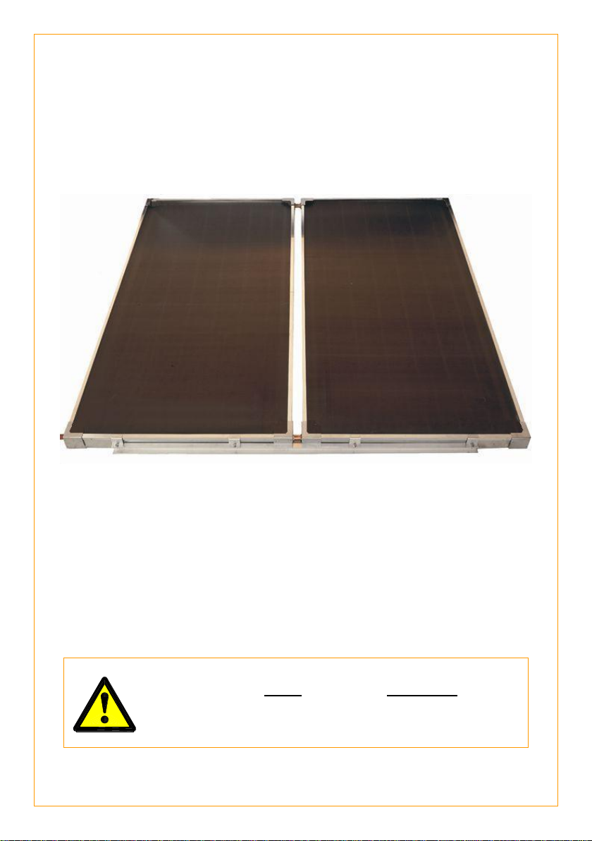
SOLAR COLLECTOR LOCATION
Consideration must be given to the position of the solar collectors in relation to
the solar storage tank. There are limitations on both the maximum length of the
solar hot and solar cold pipes and the maximum height between the solar
storage tank and the solar collectors. Refer to “Solar Storage Tank Location” on
page 5 and to “Pipe Lengths” on page 8.
The solar collectors must be installed in a shade free position.
The solar collectors are to be installed
facing toward the equator (i.e. north
facing in the southern hemisphere and
south facing in the northern
hemisphere). Where this orientation is
not practical, a system facing up to 45°
from the equator will have its efficiency
reduced by approximately 4%.
Inclination of the solar collectors should
be approximately equal to 90% of the
local latitude angle. The latitude of
some Australian cities are listed on
page 7. Solar collectors may be
installed at the roof angle for simplicity
of installation and appearance, but must
never be less than 10° from the
horizontal for an indirect closed circuit
drain back system. If the roof angle
varies by 15° from the correct angle,
efficiency will be reduced by 10%.
For a solar collector installation on a roof with a pitch less than 10°, a
Variable Pitch stand is required. Refer to your local Solar Distributor for
details.
For an installation at right angles to (across) the roof pitch, a Flat Roof stand
and an Across Pitch kit are both required. Refer to your local Solar
Distributor for details.
For an installation opposite to (against) the roof pitch, a Flat Roof stand and
an Against Pitch kit are both required. Refer to your local Solar Distributor
for details.
For an installation of collectors in a cyclonic or high wind area, a suitable
With Pitch frame (cyclone frame) is required. Refer to your local Solar
Distributor for details.