Rheem Solar Controller Kit User manual

Installation Instructions
Solar Controller Kit
(Part Number 299121)
SOLAR CONTROLLER KIT
For installation with a solar storage tank with a raised solar hot water inlet
Your solar water heater is designed for the solar collectors to be roof
mounted and the solar storage tank to be installed at ground or floor level.
This solar controller kit is designed to be mounted on the side of the solar
storage tank incorporating a raised solar hot water inlet. The solar control unit
governs the operation of the solar water heater. For full details on the
installation of the solar storage tank, the cold water plumbing supply details
and electrical connections to the tank, refer to the Owners Guide and
Installation Instructions supplied with the solar storage tank. The Owners
Guide also contains consumer information on the operation of the solar water
heater system.
PATENTS
This water heater may be protected by one or more patents or registered designs.
This solar controller kit must be installed and serviced by an authorised person.
Please leave this guide with the householder.

INSTALLATION – SOLAR CONTROL UNIT
The solar control unit is designed to be mounted on the side of the solar
storage tank, with its location above and offset from the solar cold water outlet.
The solar control unit, supplied with a 1.8 metre power cord, requires a 240 V
50 Hz general purpose outlet (GPO) located within 1.2 metres of its installation.
The GPO must have a continuous power supply originating from a circuit other
than the water heater circuit. The GPO is required to be weatherproof if
installed outdoors (refer to “Connections – Electrical” on page 8).
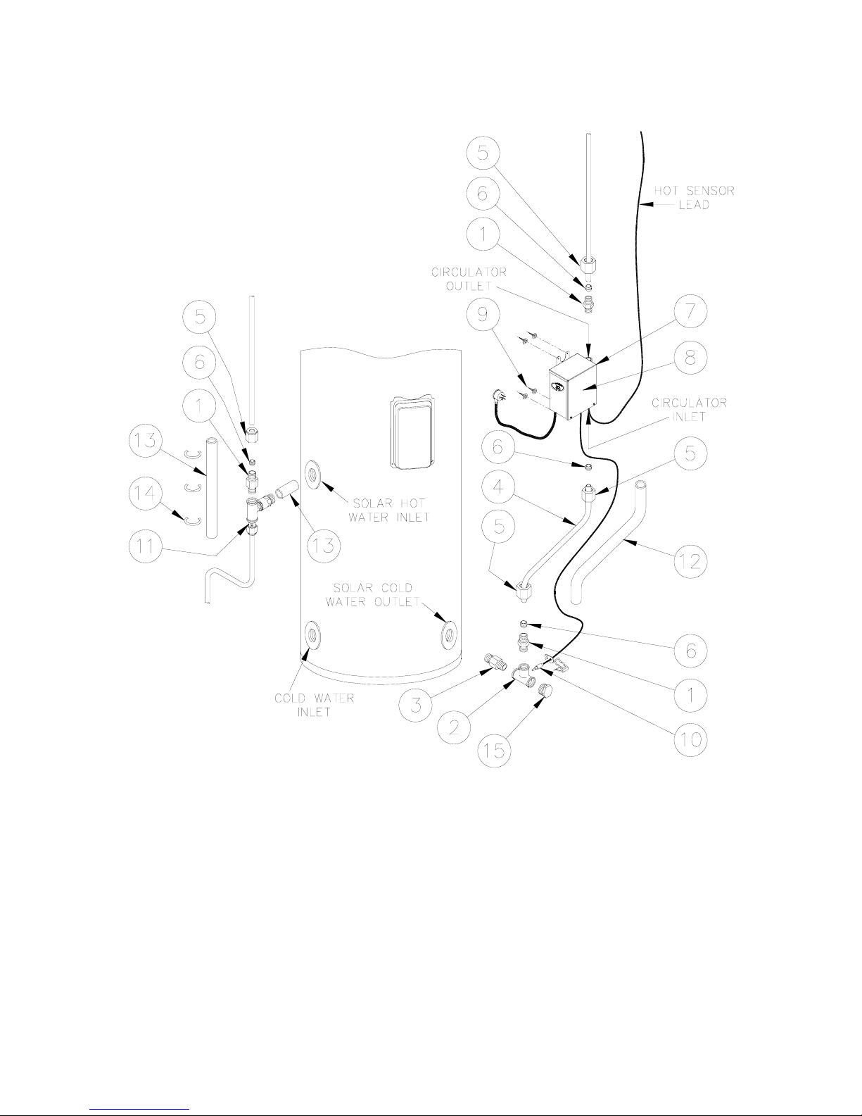
Part No Kit Components and Description - Controller Kit 299121
126554 Installation instructions solar controller kit 1
052104 Control unit solar pumped assembly 1
220342 Valve assembly air bleed and check
consisting of:
1 x 088058 fitting tee brass ½” screwed Rye 4203
1 x 088071 solar non return valve RMC ½” x ¾” SNR502
1 x 088069 fitting adaptor brass 1” F x ½” M
1 x 220340 air bleed ball valve
1 x 080123 washer 30 OD x 20 ID x 2 Salmson
1
088064 Sensor tee / nipple assembly solar pumped
consisting of:
1 x 088061 tee 3 way / cold sensor
1 x 088062 sensor nipple – solar pumped
1 x 087026 O ring 5/16” ID x 1/16” BS011 silicone
1
223603 Pipe preformed tube ½” x 240 mm long 1
080031 Screws No 8 x 13 mm 4
088063 Fitting union male ½” x ½” Rye 4910 3
088039 Fitting nipple brass ¾” x ½” 1
080079 Plug ½” BSP brass 1
Cable tie black 150 mm x 3 mm 3
Insulation pipe 12 mm ID x 280 mm long 1
Insulation pipe 35 mm ID x 150 mm long 1
Insulation pipe 35 mm ID x 50 mm long 1
Notes:
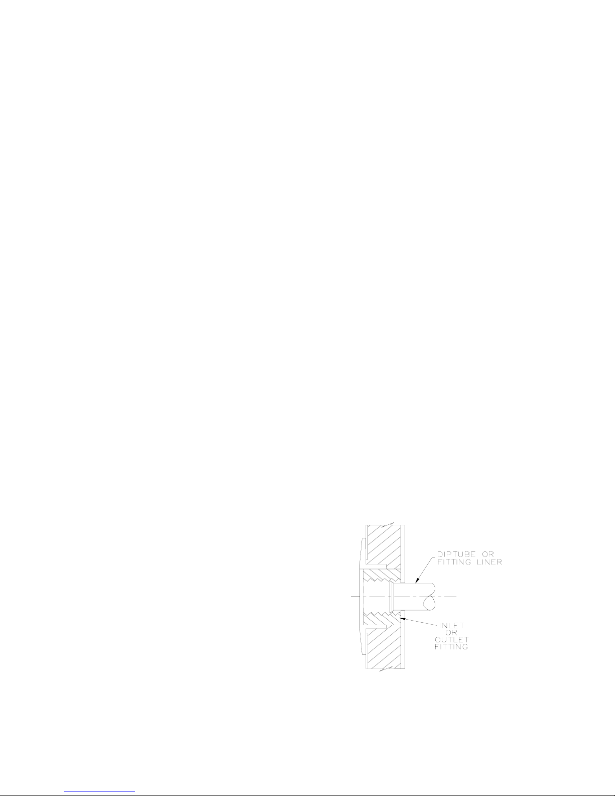
•Care must be taken when mounting the solar control unit to the side of the
solar storage tank. Damage to the cylinder as a result of mounting the solar
control unit to the jacket will void the warranty (refer to “Saddling - Pipe
Work” on page 7).
•Use thread sealing tape or an approved thread sealant on all fittings.
2

INSTALLATION – SOLAR CONTROL UNIT
3
SOLAR STORAGE TANK WITH RAISED SOLAR HOT INLET
Numbers in parentheses refer to items on diagram on page 5.
To connect the solar cold pipe and mount the solar control unit on a solar
storage tank with a raised solar hot inlet (and raised heating unit):
•Assemble a ½” x ½” hex nipple (1) into the branch outlet of the 4 way tee (2)
(ensure the compression end of the nipple is exposed) and the ½” x ¾” hex
nipple (3) in the end of the 4 way tee, so that when the assembly is fitted to
the cold water inlet of the solar storage tank, the compression nipple (1) is
orientated vertically upwards and the cold sensor housing is orientated to
the rear of the solar storage tank.
•Fit the assembly to the solar cold water outlet of the solar storage tank.
•Fit the ½”plug (15) into the end of the 4 way tee.
•Connect the DN15 preformed pipe (4) to the branch tee connection, using
the compression nut (5) and olive (6) provided, ensuring the longer straight
end is orientated upwards.
•Insulate the preformed pipe (4) with the 280 mm long x 12 mm diam
insulation (12) provided, ensuring the insulation is pushed down the full
length of the pipe.
•Fit a ½” x ½” hex nipple (1) to the outlet of the circulator (7) mounted in the
solar control unit (8) (ensure the compression end of the nipple is exposed).
•Locate the solar control unit (8) by connecting the DN15 preformed pipe (4)
to the nipple on the inlet of the circulator (7) using the compression nut (5)
and olive (6) provided.
•Secure the solar control unit (8) to the solar storage tank using the four
screws (9) provided.
•Connect the solar cold pipe (to the collector) to the nipple (1) on the outlet
side of the circulator (7) using the compression nut (5) and olive (6)
provided.
•Insert the cold sensor probe (10) into the cold sensor housing on the 4 way
tee (2), ensuring the ‘O’ ring is in position on the probe. Lock it into position
with the locking washer and clip provided.
•Connect the hot sensor lead (from the solar collector installation) to the hot
sensor cable connector at the underside of the solar control unit (8).

INSTALLATION – SOLAR CONTROL UNIT
4
To connect the solar hot pipe to the solar storage tank:
•Insulate the solar non return valve of the air bleed valve and solar non
return valve assembly (11) with the 50 mm long x 35 mm diam
insulation (13) provided.
•Fit the air bleed valve and solar non return valve assembly (11) to the solar
hot water inlet of the solar storage tank. Ensure the bleed valve outlet is
pointing vertically downwards.
•Connect a DN15 copper drain line to the bleed valve to carry the discharge
clear of the water heater and solar control unit (refer to “Bleed Valve Drain”
page 7), using the compression nut and olive provided.
•Fit a ½” x ½” hex nipple (1) to the exposed end (inlet) of the air bleed valve
and solar non return valve assembly (11) (ensure the compression end of
the nipple is exposed).
•Connect the solar hot pipe (from the collector) to the nipple (1) on the air
bleed valve and solar non return valve assembly (11) using the
compression nut (5) and olive (6) provided.
•Insulate the tee and bleed valve, from the solar hot pipe to the drain line of
the bleed valve, with the 150 mm long x 35 mm diam insulation (13) and
secure with the cable ties (14) provided.
•Insulate the drain line from the bleed valve with closed cell polymer
insulation or similar (minimum thickness 13 mm). The insulation must be
weatherproof and UV resistant if exposed.
to solar
collectors
from solar
collectors
refer to the
installation diagram
on page 5for
assembly details of
solar cold and hot
pipe connections
Solar Storage Tank with Solar Control Unit

INSTALLATION – SOLAR CONTROL UNIT
5
SUPPLIED IN SOLAR CONTROL UNIT KIT (299121)
1. Hex nipple ½” X ½”
2. 4 way tee
3. Hex nipple ½” x ¾”
4. Preformed pipe DN15
5. Compression nut
6. Olive
7. Circulator
8. Solar control unit
9. Screws
10. Cold sensor probe
11. Air bleed valve and non return valve
assembly
12. Insulation 280 mm long x 12 mm diam
13. Insulation 150 mm long x 35 mm diam &
50 mm long x 35 mm diam
14. Cable tie
15. Plug ½”

CONNECTIONS – PLUMBING
CONNECTION SIZES
•Hot water connection: RP¾/20.
•Cold water connection: RP¾/20.
•Solar hot (from collector) connection: DN15 compression fitting.
(solar hot inlet to tank RP¾/20)
•Solar cold (to collector) connection: DN15 compression fitting.
(solar cold outlet from tank: RP¾/20)
•Relief valve connection: RP½/15.
•Bleed valve connection: G1.0B.
All plumbing work must be carried out by a qualified person and in accordance
with the National Plumbing Standard AS/NZS 3500.4 and local authority
requirements.
WATER INLET AND OUTLET
All pipe work must be cleared of foreign matter before connection and purged
before attempting to operate the water heater. All olive compression fittings
must use brass or copper olives. Use thread sealing tape or approved thread
sealant on all fittings.
Refer to the Owners Guide and Installation Instructions supplied with the solar
storage tank for the plumbing arrangement to be used for connecting the cold
water supply line to the solar water heater system. The plumbing arrangements
for the solar cold and solar hot pipes are shown on page 5.
A disconnection union must always be
provided at the cold water inlet, solar cold
water outlet, solar hot water inlet and hot
water outlet on the water heater to allow
for disconnection of the water heater.
This water heater has either a plastic dip
tube or fitting liner in the inlet and outlet
fittings (see diagram). These must be in
place for the water heater to function
properly. Do not remove or damage them
by using heat nearby. They will be pushed
into the correct position as the fitting is
screwed in.
6

CONNECTIONS – PLUMBING
7
BLEED VALVE DRAIN
A copper drain line must be fitted to the bleed valve to carry the discharge clear
of the water heater and solar control unit. Connect the drain line to the bleed
valve using a disconnection union. The pipe work from the bleed valve to the
drain should be as short as possible and fall all the way from the valve with no
restrictions. It should have no more than three right angle bends in it. Use
DN15 pipe.
The outlet of the drain line must be in such a position that flow out of the pipe
can be easily seen (refer AS/NZS 3500.4) - but arranged so water discharge
will not cause injury, damage, nuisance or splashing. The water discharged
may be of a high temperature under certain conditions. The drain line must be
fully insulated with closed cell polymer insulation or similar (minimum thickness
13 mm). The insulation must be weatherproof and UV resistant if exposed.
SADDLING - PIPE WORK
To prevent damage to the cylinder when attaching pipe clips or saddles to the
water heater jacket, we recommend the use of self-drilling screws with a
maximum length of 13 mm. Should pre drilling be required extreme caution
must be observed when penetrating the jacket of the water heater.
Note: Damage to the cylinder as a result of saddling to the jacket will void
the warranty.

CONNECTIONS – ELECTRICAL
The power supply to the water heater must not be switched on until the
water heater is filled with water and a satisfactory megger reading is
obtained.
All electrical work and permanent wiring must be carried out by a qualified
person and in accordance with the Wiring Rules AS/NZS 3000 and local
authority requirements.
The solar control unit, supplied with a 1.8 metre power cord, requires a 240 V
50 Hz general purpose outlet (GPO) to be located within 1.2 metres of the
installation. The GPO must have a continuous power supply originating from a
circuit other than the water heater circuit. The GPO is required to be
weatherproof if installed outdoors.
If the power supply cord or plug is damaged, it must be replaced by an
authorised person in order to avoid a hazard. The power supply cord and plug
must be replaced with a genuine replacement part available from Rheem,
Solahart or Edwards.
8

SOLAR CONTROLLER AND SOLAR MONITOR
SOLAR MONITOR
A solar monitor is located on the side of the solar control unit and houses a
green and a red LED.
The green LED, marked “Solar”, indicates the current operational mode of the
solar water heater and the red LED, marked “Attention”, indicates a fault mode.
The green LED will emit either a constant glow or a series of flashes, with a
2 second interval between each series.
The red LED will emit a series of flashes, with a 2 second interval between
each series, only if there is a particular fault condition with the system.
9

SOLAR CONTROLLER AND SOLAR MONITOR
10
COMMISSIONING
Refer to the installation instructions supplied with the solar storage tank for the
complete commissioning procedure.
When the electrical supply is switched on to the solar control unit at start up:
•If there is no solar gain, the circulator will not activate and the green LED
will emit a slow pulse.
The slow pulse indicates the circulator is not activated and the power to the
solar control unit has been on for less than 48 hours.
•If there is solar gain, the circulator activates and the green LED will emit a
series of three (3) flashes.
The three (3) flashes indicate the circulator is operating and power to the
solar control unit has been on for less than 48 hours.
•The circulator will operate at full speed for approximately fifteen (15)
seconds. If the red LED is emitting a rapid pulse, the circulator may operate
at full speed for up to ten (10) minutes.
After fifteen (15) seconds or after the red LED has extinguished, the solar
controller will commence to pulse the circulator to control the flow rate
through the collector circuit and achieve a constant temperature rise across
the collector(s). It is normal operation for the circulator to experience a
pulsing effect.
•The red LED may emit a rapid pulse for a short period.
This indicates a temperature difference between the hot sensor and cold
sensor of greater than 40°C and does not represent a fault code. This is the
result of a build-up of heat and increase in water temperature in the
collector prior to the switching on of the electrical supply to the solar control
unit.
The rapid pulsing of the red LED will cease as the water circulates and the
heat is dissipated. This should be within four (4) to five (5) minutes of start
up, but may take up to ten (10) minutes.
If the red LED does continue to emit a rapid pulse for longer than ten (10)
minutes, this may indicate water is not circulating through the collectors and
solar circuit:
switch off the electrical supply at the power outlet to the solar control unit
repeat the procedure to bleed the solar collectors
switch on the electrical supply at the power outlet to the solar control unit

SOLAR CONTROLLER AND SOLAR MONITOR
11
DIAGNOSTIC FEATURES OF THE SOLAR CONTROLLER
The operational modes are:
Flashes Operational Modes
solid green
(remains on) Standby mode
green
slow pulse
Standby mode
(power on for less than 48 hours)
green
rapid pulse Circulating water through collectors
3 x green Circulating water through collectors
(power on for less than 48 hours)
no green
(remains off) Power outage or call for service
Flashes Fault Modes
red
rapid pulse
Temperature rise across collector greater than 40°C
(circulator at full speed)
3 x red Hot sensor in collector – short circuit
4 x red Hot sensor in collector – open circuit
5 x red Cold sensor –short circuit
6 x red Cold sensor – open circuit
If the power supply to the solar control unit is on and the green LED is off or the
red LED is flashing, this indicates there may be a fault with the water heater.
The red LED may emit up to six flashes in each series of flashes.
Note: During periods of high solar radiation and if the circulator activates after
having been off, such as during start up, it is possible the red LED may emit a
rapid pulse for a period of up to ten (10) minutes. This does not indicate a fault.
Refer to “Commissioning” on page 10 for the possible green and red LED
flashing sequence during start up procedure.
If the red LED continues to emit a rapid pulse for longer than ten (10) minutes,
or emits a series of flashes, then count the number of flashes and phone your
nearest Service Department or Accredited Service Agent to arrange for an
inspection.

Your solar water heater and its components are covered by a comprehensive
warranty. For full warranty details, refer to the Owners Guide and Installation
Instructions supplied with the solar storage tank.
RHEEM AUSTRALIA PTY LTD
A.B.N. 21 098 823 511
www.rheem.com.au
FOR SERVICE TELEPHONE
131 031 AUSTRALIA
0800 657 335 NEW ZEALAND
or refer local Yellow Pages
Note: Every care has been taken to ensure accuracy in preparation of this publication. No
liability can be accepted for any consequences, which may arise as a result of its application.
12
Revision Date: 2007 November 126554C
This manual suits for next models
1
Table of contents
Other Rheem Inverter manuals
Popular Inverter manuals by other brands

SUNBEAMsystem
SUNBEAMsystem MOONRAY Series user manual

Daikin
Daikin RKC09NV2S Service Manual Removal Procedure

Mid-Continent Instrument
Mid-Continent Instrument TRUE BLUE POWER TI1200 Series Installation manual and operating instructions

Emheater
Emheater EM15-SP Series user manual

Gondzik
Gondzik NL-BKDX30-95II/R user manual

SolarEdge
SolarEdge BI-EU1P Quick installation guide