manuals.online logo
Brands
  1. Home
  2. •
  3. Brands
  4. •
  5. Rheodyne
  6. •
  7. Laboratory Equipment
  8. •
  9. Rheodyne Model 7010 User manual

Rheodyne Model 7010 User manual

Operating Instructions
Type 70 High Pressure Switching Valves
Model 7010 Sample Injector
1.0 DESCRIPTION
Rheodyne’s Type 70 valves are high
pressure switching valves: 7000, 7000L,
7030, 7030L, 7040, 7040L, 7060 and 7060L.
Unless otherwise indicated, statements about
non-L models apply also to the L models.
Model 7010 is a sample injector. An
accessory Loop Filler Port (P/N 7012) is
needed to load sample into Model 7010. If
your valve is to be operated with a Rheodyne
actuator, refer also to the separate actuator
instructions.
Figure 1 shows a schematic flow diagram
of each of the switching valves. The circles
represent the ports in the valve stator. The
dark grooves are the connecting passages in
the rotor seal.
Rotation of the valve shaft through 60°
switches the valve from one position to the
other. Models 7010, 7000, 7030, and 7040
are two-position valves with stops that
restrict the rotation of the valve to 60° turns.
Model 7060 is a six-position valve. A spring-
loaded detent mechanism is included which
allows continuous rotation and insures that
the shaft “falls into” each of the six positions
at the precise 60° spacing.
2.0 SUPPLIED WITH THE VALVE
Supplied with the valve in a separate bag
are RheFlex®stainless steel fittings sets for
all ports and the following items. A 20 µL
sample loop is supplied with Model 7010.
A joining tube is supplied with Model 7040.
• Hex Key(s)
• Mounting Screws (2)
3.0 SPECIFICATIONS
• Maximum Operating Pressure: Model
7010 and Type 70 non-L models -
48 MPa (483 bar, 7000 psi); L models -
34 MPa (345 bar, 5000 psi)
• Maximum Operating Temperature:
Models 7010, 7000, 7030, 7040, and
L models - 150°C; Model 7060 - 80°C
• Flow Passage Diameters: Models 7010,
7000, 7030, 7040 - 0.5 mm (0.018") and
0.6 mm (0.024"); Model 7060 - 0.5 mm
(0.018") and 0.4 mm (0.016");
L models - 1 mm (0.040")
• Wetted Surfaces: stainless steel and an
inert polymer
• Ports in all models accept 10-32 male
threaded fittings
4.0 IMPORTANT SAFETY NOTICES
4.1 Warning: (Using 7010 as an injector):
When using sample loops larger than
100 µL, shield yourself from mobile phase
coming out of the needle port when the valve
is turned from INJECT to LOAD. Example:
1 mL loop ejects 20 µL upon decompression
from 19 MPa (200 bar, 2898 psi).
4.2 Caution: Do not mount the valve with
the ports facing up. Leakage due to a
damaged rotor seal or loose fittings can
cause the bearings to corrode.
4.3 Caution: Rinse the valve thoroughly
after using buffer solutions to prevent salt
crystals from forming, which can cause
damage to the rotor seal and stator face
assembly.
5.0 INSTALLATION
All valves can be panel mounted:
a) Remove the handle assembly by
loosening the knob set screw(s).
b) Fasten the valve to the panel using the
two mounting screws supplied.
On Model 7060, the two screws that hold
the detent mechanism on the valve should
be removed before fastening the valve to the
panel. If the detent mechanism needs to be
disabled, as is required when installing a
pneumatic actuator around Model 7060,
refer to Section 8.4.
5.1 MODEL 7010 INJECTOR
Model 7010, as a sample injector, connects
to different system components.
a) Connect an accessory injection port to
Port 5 and the vent line to Port 6. Place the
injection port at the same horizontal level as
Vent Line 6 to avoid siphoning.
b) Connect the pump to Port 2 and the
column to Port 3. Leave the column
disconnected from the valve during initial
Position A Position B
Models 7000 & 7010
Two-Position, Six-Port
Position A Position B
Model 7030
Three-Way
Position BPosition A
3
24
5
1
3
24
65
1
6
Model 7060
Six-Position
3
2
4
6
75
1
Position A Position B
Model 7040
Four-Way
24
6
5
1
3
24
6
5
1
3
Fig. 1. Flow diagrams of Rheodyne Type 70 high pressure switching valves. Page 1 of 4
2320666B
6/02
24
6
5
1
3
24
6
5
1
3
Position A Position B
Rheodyne LLC • A Unit of IDEX Corporation • 600 Park Court, Rohnert Park, CA 94928 • (707) 588-2000 • Fax (707) 588-2020
www.rheodyne.com
flushing.
6.0 OPERATION
6.1 INJECTIONS (MODEL 7010 ONLY)
Before connecting the column to the
injector, flush the injector with mobile phase
in both the LOAD and INJECT positions.
After flushing the injector, turn to LOAD,
and connect the column.
6.1.1 LOADING THE SAMPLE LOOP
Overfill the loop with at least two to five
loop volumes of sample. Six to ten loop
volumes will provide even better precision.
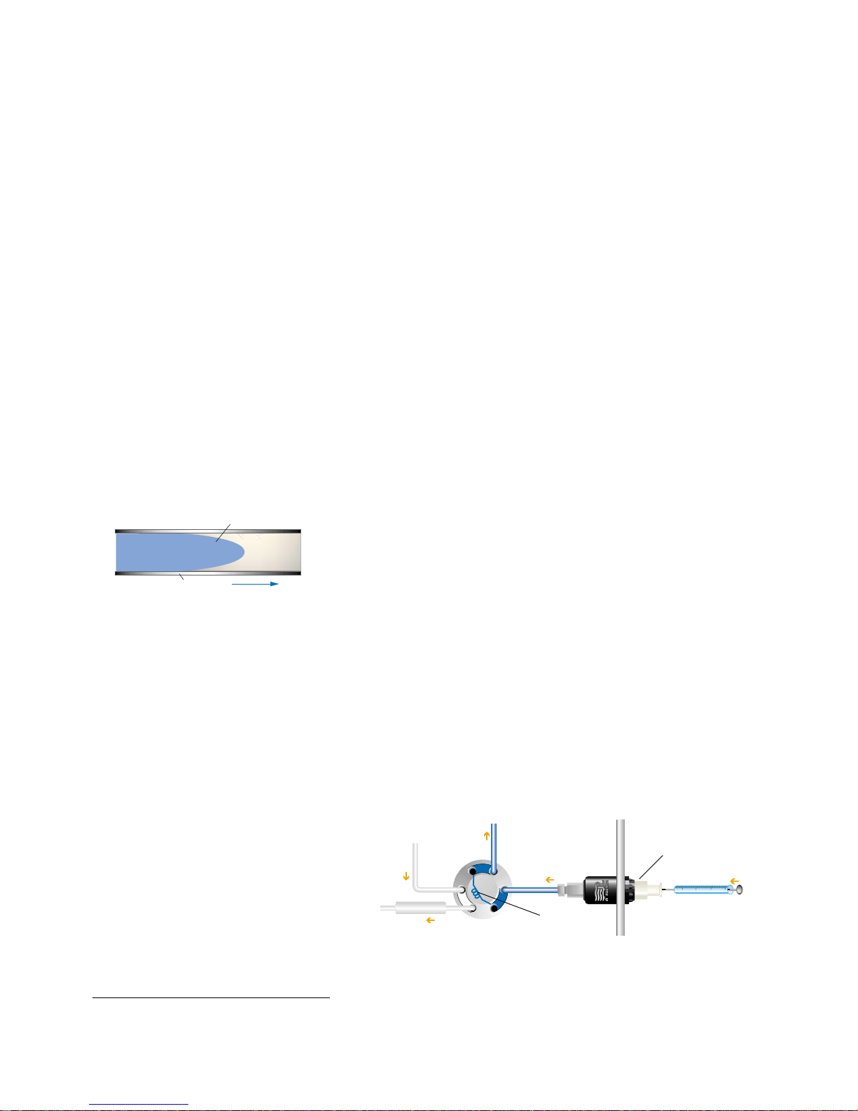
An excess of sample is needed because
mobile phase near the wall of the loop is
displaced slowly due to the laminar flow
effect shown in Figure 2.
To completely fill the loop (see Figure 3):
a) See Warning 4.1 and turn to LOAD.
b) Insert the syringe into the accessory
injection port.
c) Load the sample.
d) Leave the syringe in position and turn to
INJECT.
6.2 SUGGESTED APPLICATIONS FOR
SWITCHING VALVES
Flush the valve with mobile phase before
connecting the valve to system components.
Suggested applications for switching valve
applications are shown in Figures 7, 8, 9, and
10.
7.0 ADJUSTING FOR LEAKAGE OR
HIGHER PRESSURE OPERATION
The three small set screws in the stator (see
Figure 4) have been factory set so that when
the three stator screws are fully tightened, the
spring force between the valve rotor and
stator is sufficient to hold the indicated
pressure. If leakage is to be corrected, or if
operation at a higher pressure is to be done,
proceed as follows: The three set screws
should be loosened about 1/20 turn each (18°
of rotation) and the three stator screws
tightened an equal amount. If this new
setting fails to accomplish leak-free
operation at the desired pressure, repeat the
procedure by an additional 1/20 turn. Avoid
excessive tightening which will only
increase wear of the rotor seal. If it is
necessary to loosen spring tension, either to
lower the operating pressure, or to adjust for
a new rotor seal, which may be thicker than
the one being replaced, reverse the above
procedures. For example, first loosen the
stator screws, then tighten the set screws.
If leakage cannot be stopped by tightening
the valve, or if, as a result of tightening to
stop the leakage, the handle is too hard to
turn, the rotor seal needs replacing. See next
section.
8.0 MAINTENANCE
The only parts that may need eventual
replacement are the rotor seal and isolation
seal. Abrasive particles in the sample can
damage the rotor seal.
Genuine Rheodyne parts are easily replaced
by the following instructions.
8.1 DISASSEMBLY
To disassemble the valve, refer to Figure 4
and proceed as follows:
a) Remove the three stator screws.
b)Remove stator and stator ring from
valve body.
c) Pull the rotor seal off of the pins.
d)Remove the isolation seal.
8.2 REASSEMBLY
8.2.1 TWO-POSITION VALVE REASSEMBLY
To reassemble Models 7010, 7000, 7030,
and 7040, refer to Figures 4 and 6 and
proceed as follows:
a) Mount the new isolation seal onto the
shaft with the open side facing the handle.
b) Be sure that the rotor seal is correctly
oriented as shown in Figure 6 with rotor seal
grooves facing the stator and with the notch
in the metal rim of the rotor seal in line as
shown (the notch also faces the stator).
c) In replacing the stator ring, be sure that
the two stop pins are still in their holes in the
stator ring, then push the stator ring squarely
onto the shaft assembly allowing the stop
pins to enter the mating holes in the body. Be
sure the rotor pin is located between the two
stop pins (Model 7060 does not have a rotor
pin so the rotor can be in any position).
d) Replace the stator by first pushing it
onto the two pins on the stator ring and then
adding the three stator screws. Tighten each
screw a little at a time to keep the stator
surface parallel to the stator ring surface. If
the three set screws in the stator were left
unchanged, tighten the three stator screws a
1/2 turn past fingertight. The three set screws
will ensure that the gap between stator and
stator ring is uniform and in the original
position before disassembly.
e) If the set screws need adjusting because
a new rotor seal was installed or because
leakage has to be stopped, each set screw
should be turned an equal amount to ensure
that after the stator screws are retightened,
the gap between the stator and stator ring is
uniform all around. Refer also to Section 7.0.
8.2.2 MODEL 7060 REASSEMBLY
An arrow has been engraved on the knob
end of the shaft. Orient the rotor seal on the
rotor as shown in Figure 6 relative to this
arrow (with the grooves in the rotor seal
facing the stator).
Follow the steps in Section 8.2.1.
8.3 ATTACHING HANDLE
The knob for the Model 7060 has a single
set screw located opposite the black handle.
The knob should be oriented on the Model
7060 shaft so that the knob pointer points in
the same direction as the arrow on the end
of the shaft. The set screw should be
tightened on the flat of the shaft with the tip
of the set screw centered on the hole in the
shaft. Confirm this centering before final
tightening of the set screw.
The knob for the two-position valves has
two set screws, both at 90° from the black
handle. It is best to tighten only the one set
screw on the flat of the shaft although both
set screws can be tightened. Confirm that
the set screw tip is centered on the hole in
the shaft before tightening (remove one set
screw to observe alignment while tightening
the other).
Fig. 2. Laminar flow effect.
Flow
Sample
TubeWall
Mobile Phase
Waste
3
2
4
6
5
1
Column
Pressure
Loading Instrument Panel
or Mounting Bracket
Syringe
Sample Loop
Loop Filler
Port
Pump
Fig. 3. Using a Loop Filler Port to fill the loop by pressure loading.
Page 2 of 4
2320666B
6/02
Rheodyne LLC • A Unit of IDEX Corporation • 600 Park Court, Rohnert Park, CA 94928 • (707) 588-2000 • Fax (707) 588-2020
www.rheodyne.com
8.4 DETENT MECHANISM ON
MODEL 7060
If mounting Model 7060 on an actuator, the
detent mechanism must be disabled (refer to
Figure 5):
a) Remove the detent pin and centering
ring.
b) Push the detent pin into the holes in the
centering ring and the shaft.
c) Center the pin, making each end project
equally from the ring OD.
d) Rotate the body while pushing the detent
body in place to allow the detent pin to fall
into the two notches in the detent wheel.
e) Rotate the body while holding the detent
body in place to allow the mounting holes to
line up with the threaded mounting holes in
the valve body.
9.0 OPERATING SUGGESTIONS
9.1 USE OF AQUEOUS BUFFERS OR
SALT SOLUTIONS
To prevent the formation of salt crystals in
the valve, flush out the flow passages with
water after using salt solutions.
9.2 USE OF HIGH pH SOLUTIONS
The standard rotor seal is Vespel1, which
has exceptionally good wear resistance.
However, Vespel is susceptible to alkaline
attack, deteriorating rapidly when used with
solutions of pH over 10. PEEK and
Tefzel1 rotor seals are available for alkaline
applications.
9.3 ACCURACY OF SAMPLE LOOPS
Sample loop sizes are not actual values.The
actual volume can differ by ± 10% for a 20
µL loop and ±5% for a 10 mL loop. There is
a greater difference for smaller loops.
Detent Housing Ball (2)
Spring (2) Detent Wheel Centering Ring
Detent Pin
Stator Screws (3)
Knob
Shaft Assembly Stator Pins (2)
Stator
Set Screws (3)
Stator Ring
Stop Pins (2)
Rotor Seal
Isolation Seal
Bearing Ring
Rotor Pin
Spring Washers (4)
Thrust Bearing
Body
Shaft
* Shaft Assembly includes Shaft,
Rotor, and Pins.
*
Stop Pins Rotor Pin
Notch
Model
7060
Model
7030
Models
7010, 7000 & 7040
Shaft End
Fig. 6. Correct rotor seal orientation (viewed from stator).
Fig. 4. Exploded view ofType 70 valves.
Handle
Assembly
Page 3 of 4
2320666B
6/02
Fig. 5. Detent mechanism on Model 7060.
Rheodyne LLC • A Unit of IDEX Corporation • 600 Park Court, Rohnert Park, CA 94928 • (707) 588-2000 • Fax (707) 588-2020
www.rheodyne.com
10.0 RECOMMENDED SPARE PARTS
The only parts that may need eventual
replacement is the rotor seal and the isolation
seal. Genuine Rheodyne rotor seals are
easily replaced by following the instructions
in Section 8.0.
Table I shows the Rheodyne part numbers
for the replacement rotor seal:
Table I. Standard L
Model Models Models
7000 and
7040 7010-039 7000-016
7030 7030-003 7030-014
7060 7060-070 7060-064
A convenient alternative to separate
replacement part ordering is the Rheodyne
RheBuild®Kit for Models 7010, 7000 and
7040. The RheBuild Kit includes all
necessary parts, tools, and instructions to
maintain the quality performance of your
Rheodyne valve.
7010-999 RheBuild Kit for 7010,
7000, and 7040.
11.0 WARRANTY
All Rheodyne products are warranted
against defects in materials and
workmanship for a period of one-year
following the date of shipment by Rheodyne.
Rheodyne will repair or replace any
Rheodyne product that fails during the
warranty period due to a defect in materials
or workmanship at no charge to the
customer. The product must be returned to
Rheodyne’s factory in original packaging or
equivalent, transportation prepaid. Damage
occurring in transit is not covered by the
warranty. This limited warranty is
Rheodyne’s sole warranty of its products,
and all other warranties of merchantability or
fitness for any particular purpose are hereby
disclaimed.
Under no circumstances will Rheodyne be
liable for any consequential or incidental
damages attributable to a claimed failure of a
Rheodyne product, even if Rheodyne has
been placed on notice of possibility of such
damages.
Detector
Column B
Position A
Column A
3
2
4
6
5
1
Sample Injector
Detector
Column B
Position B
Column A
3
2
4
6
5
1
Sample Injector
Fig. 7.Two column selection using Model 7000.
Detector A
2
1
3
5
4
6
Column
Position B
Sample
Injector Pump A
1.00
Detector B
Position A
2
1
3
5
4
6
Column
Sample
Injector Pump A
1.00
Detector A
Detector B
Fig. 9. Diverting flow from one detector to the
other using Model 7030.
Fig. 8. Illustration of column flow reversal for
backflushing using Model 7040.
Detector
Column
Column
Pump
34
6
5
1
Detector
Position A (Forward Flow)
Position B (Reverse Flow)
3
2
4
6
5
1
Sample Injector
1.00
Pump
2
Sample Injector
1.00
Fig. 10. Six column selection using two
Model 7060 switching valves.
Detector
3
2
4
6
75
1
3
2
4
6
5
1
12 3 456
Pump
Sample
Injector
1.00
1Tefzel and Vespel are trademarks of E.I. DuPont.
Page 4 of 4
2320666B
6/02
Rheodyne LLC • A Unit of IDEX Corporation • 600 Park Court, Rohnert Park, CA 94928 • (707) 588-2000 • Fax (707) 588-2020
www.rheodyne.com

Other Rheodyne Laboratory Equipment manuals

Rheodyne 7125 User manual

Rheodyne

Rheodyne 7125 User manual

Rheodyne 8125 User manual

Rheodyne

Rheodyne 8125 User manual

Popular Laboratory Equipment manuals by other brands

N-BIOTEK NB-205QM operating manual

N-BIOTEK

N-BIOTEK NB-205QM operating manual

overhoff TASC-HTO-HT-C14 Operation & maintenance manual

overhoff

overhoff TASC-HTO-HT-C14 Operation & maintenance manual

Fotric 326 Quick start manual

Fotric

Fotric 326 Quick start manual

Thermo Scientific TSE Series Operating and maintenance manual

Thermo Scientific

Thermo Scientific TSE Series Operating and maintenance manual

WLD-TEC Sensorturn pro instruction manual

WLD-TEC

WLD-TEC Sensorturn pro instruction manual

Labnet D0100 instruction manual

Labnet

Labnet D0100 instruction manual

Cascade Sciences CVO-5-EX Series Installation & operation manual

Cascade Sciences

Cascade Sciences CVO-5-EX Series Installation & operation manual

Miele A 814 operating instructions

Miele

Miele A 814 operating instructions

Steinberg Systems SBS-LAB-107 user manual

Steinberg Systems

Steinberg Systems SBS-LAB-107 user manual

Lafayette Instrument 82400SS user manual

Lafayette Instrument

Lafayette Instrument 82400SS user manual

KVARZ CH1-76A operating manual

KVARZ

KVARZ CH1-76A operating manual

BioLAB BFSD-502 Operation manual

BioLAB

BioLAB BFSD-502 Operation manual

Graco PR70 Series Instructions - parts

Graco

Graco PR70 Series Instructions - parts

DrBrowns AC178-INTL Instructions for use

DrBrowns

DrBrowns AC178-INTL Instructions for use

Beckman Industrial L8-70 manual

Beckman Industrial

Beckman Industrial L8-70 manual

Kinematica MICROTON SYSTEM MB 950 G instruction manual

Kinematica

Kinematica MICROTON SYSTEM MB 950 G instruction manual

Molecular Devices StakMax user guide

Molecular Devices

Molecular Devices StakMax user guide

LIAD ColorSave 1000ST-INJ user manual

LIAD

LIAD ColorSave 1000ST-INJ user manual

manuals.online logo
manuals.online logoBrands
  • About & Mission
  • Contact us
  • Privacy Policy
  • Terms and Conditions

Copyright 2025 Manuals.Online. All Rights Reserved.