Rhino Shelter Round Style Portable Building User manual

Assembly Instructions 30x30x15 Round Style Portable Building
Version 2.3
Please DO NOT return unit to store or dealer. For all questions or shortages please contact
Customer Service at: 800-447-7079 or 203-877-7070
1
ASSEMBLY INSTRUCTIONS
ROUND STYLE 30x30x15
Please read instructions completely before you
begin. This will help attain the best results for your
installation.
CONGRATULATIONS!
Congratulations on your purchase of a Rhino Shelter
30x30x15 Round Style Portable Building. With proper
installation, use and maintenance, your new unit will
provide many years of good and suitable service. Your
new Rhino Shelter portable enclosure is a combination
of excellent engineering and well thought out design.
The unit is comprised of a rigid tubular frame, covered
with a long life polyethylene cover and double door ends.
The multiple part frame assembly is pre-drilled for easy
insertion of frame bolts. The tubing is made from high-
grade galvanized steel., resisting moisture and oxidation
over the life of the shelter. The cover and doors are
made from ASTM-5 approved polyethylene materials.
The cover is UV protected for exposure to sunlight.
SAFETY WARNING
The installation of this unit must conform to the
requirements of all authorities having jurisdiction in
your specific local area. In the absence of such
requirements, the assembly and installation must
conform to the provided assembly and installation
instructions. Rhino Shelter will not responsible for
failure to comply with any requirements in a given
local area. Damages, consequential damages, or
injuries caused by improper installation, alteration,
improper use, or damages caused by snow, wind, or
any acts of nature are strictly that of the user. Unit is
not intended for occupancy for any length of time.
NO running of internal combustion engines, open
flames or contact with heated surfaces is allowed.
For installation assistance or Customer Service, please
call 800-447-7079 or 203-877-7070, 8AM-5PM EST.
Cartons should be inspected upon delivery from carrier,
and any evident damages should be noted on the bill of
lading before signing. If upon opening the cartons hidden
damage is discovered, contact carrier or it’s agent
immediately. Claims for shipping damage MUST be
made with the shipping company. An inspection of the
goods will most likely be required. Do not discard
packing or any components before the freight company
inspection. All claims for freight damage must be made
within 15 days of receipt of the goods in accordance with
ICC regulations.
ASSEMBLY PROCEDURE
The proper sequence and steps to install this unit will
produce a proper and good installation. Failure to read
and follow these guidelines may result in an improper
installation and will void all warranty and protection the
owner is entitled to with the product. The steps to be
undertaken are:
1. Perform an inventory check before beginning, to
be certain all components are available for
installation.
2. Prepare location and place all unit boxes near
location sight.
3. Assemble Seven (7) Arch Assemblies of unit.
4. Assemble unit End Arch, first Interior Arch, and
Wind Braces with the first ridge crest, base, and
side rail sections.
5. Add additional Arch Assemblies with each
section of base rails and side rails.
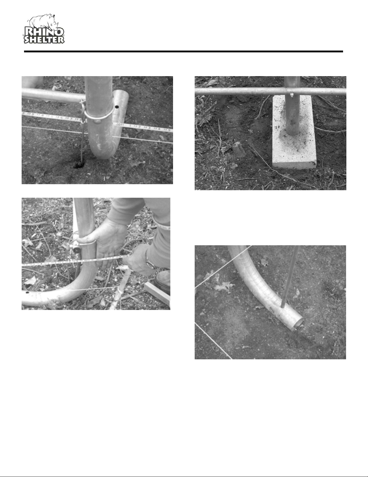
6. Level and square Frame of Unit.
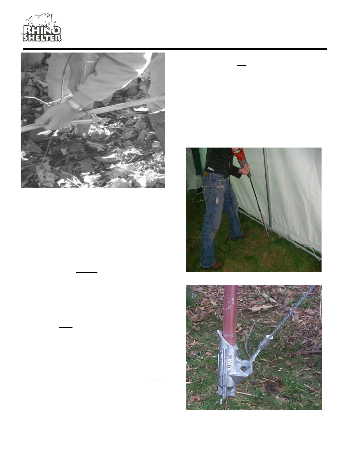
7. Anchor frame assembly to ground with provided
anchors, U-bolts and drive rod.
8. Install Doors (2) on ends of frame assembly.
9. Install Main Cover over frame assembly.
10. Install Door Roll-up kits
TOOLS REQUIRED
The following hand tools will be needed for proper
installation of your new Rhino Shelter building:
9/16 Open End Wrench
9/16 Socket or Box Wrench
Large Flat Head Screwdriver
2lb maul or Sledgehammer
2 Foot Level
12’ Step Ladder
Stakes & String for squaring Frame
INVENTORY CHECK
Start installation procedure by removing all components
from packaging to ensure all components are present.
Inventory chart appears on the last page of this manual.

Assembly Instructions 30x30x15 Round Style Portable Building
Version 2.3
Please DO NOT return unit to store or dealer. For all questions or shortages please contact
Customer Service at: 800-447-7079 or 203-877-7070
2

Assembly Instructions 30x30x15 Round Style Portable Building
Version 2.3
Please DO NOT return unit to store or dealer. For all questions or shortages please contact
Customer Service at: 800-447-7079 or 203-877-7070
3
#1
#1
#1
#1

Assembly Instructions 30x30x15 Round Style Portable Building
Version 2.3
Please DO NOT return unit to store or dealer. For all questions or shortages please contact
Customer Service at: 800-447-7079 or 203-877-7070
4

Assembly Instructions 30x30x15 Round Style Portable Building
Version 2.3
Please DO NOT return unit to store or dealer. For all questions or shortages please contact
Customer Service at: 800-447-7079 or 203-877-7070
5
Use Carriage Bolts with Washers and Nuts through
pre-drilled holes in frame members. (refer to detail of
arch assembly for correct hardware) Be certain to insert
carriage bolts from the outside into the interior of the
unit, with the washers and nuts on the inside of the
frame. This will prevent the bolts from puncturing
through the cover material. Do not tighten down the nuts
completely until frame is fully assembled and set in
place.
SITE PREPARATION
Select a level or as close to level as practical location for
your Rhino Shelter Building. The building should be
placed on a base of materials suitable for the storage
load to be protected. The unit should not be located
under trees, which will shed hard fruit such as apples,
walnuts, or heavy pine cones. The cover of your unit will
protect against normal falling leaves and light debris,
however, large branches or other falling items may
cause a puncture or tear in the cover material.
STEP 2. ATTACH CORNER WIND BRACES TO
FRONT AND REAR END ARCHES
Take notice of drainage around your intended location.
Water draining from the surrounding terrain should be
planned so that it does not run into the unit. As well, rain
or melting snow hat comes off the unit should be drained
away rather than accumulate and pool around the unit.
Attach Corner Wind Braces #6 CW-7005 to the INSIDE
of EACH side of the End Arches you assembled in step
1. Refer to detail drawing for correct hardware. Do not
tighten completely.
Check to be certain that adequate clearance is allowed
for entry and exit from ends of the unit. As unit has doors
on both ends, ideally boat or equipment can be inserted
or removed from either end.
STEP 3. ASSEMBLE THE REMAINING (4) FOUR
INTERIOR ARCHES
Each INTERIOR ARCH consists of:
Using the stakes and string, measure off and square
area for intended installation. Level the ground as best
as possible.
3 - #1 CT-7006 Crest Tube-swedged end
1 - #2 CT-7007 Crest Tube-plain ends
2 - #3 CT-7008 Arch Side Tube
A properly leveled frame yields maximum strength. 2 - #5 EUL-7003 Arch End Upright –plain base
Use Carriage Bolts with Washers and Nuts through pre-
drilled holes in frame members. Refer to detail drawing
for correct hardware. Be certain to insert carriage bolts
from the outside into the interior of the unit, with the
washers and nuts on the inside of the frame. Do not
tighten down the nuts completely.
ARCH AND FRAME ASSEMBLY
STEP 1. ASSEMBLE THE FRONT & REAR END
ARCHES AND #4 MIDDLE ARCH W/FEET
(3 ARCHES)
Each ARCH consists of:
3 - #1 CT-7006 Crest Tube-swedged end
1 - #2 CT-7007 Crest Tube-plain ends
2 - #3 CT-7008 Arch Side Tube
2 - #4 EUL-7002 Arch End Upright with Foot

Assembly Instructions 30x30x15 Round Style Portable Building
Version 2.3
Please DO NOT return unit to store or dealer. For all questions or shortages please contact
Customer Service at: 800-447-7079 or 203-877-7070
6
STEP 4. START COMBINING ARCH SECTIONS
TO BUILD FRAME
Stand first End Arch Assembly up and support with the
wind brace temporarily. Attach #7 ECR-7003 Plain End
Cross Rails to the inside of the End Arch Assembly
using 4” Carriage bolts, washers and nuts through the
pre-drilled holes. Again do not tighten down completely.
Always remember to insert bolts from the outside into
the interior to prevent damage to cover.
Stand an Interior Arch Assembly (without feet) assembly
into place about 60” from end arch assembly. Align
holes in Arch with Cross Rails. Using 4” Carriage Bolts,
with nuts and washers connect the Side Cross Rails
between the arches. Connect Wind Brace from End
Arch Assembly To first Interior Arch. This will make the
first two arches self-supporting. Insert next Cross Rail
into the base and Side Rails for the next arch assembly.
STEP 5. TOP RIDGE CREST CROSS RAIL
Begin the Top Ridge Crest Cross Rail by placing the first
end UNDER the End Arch Assembly, secure loosely with
carriage Bolt CBN-7005-3, with washer and nut facing
interior of unit.
Under End
Arch
Over
Interior Arch
STEP 6. CONNECT ADDITIONAL ARCHES
Add Interior Arch Assembly #3 to the first two arches
assembled in Step 4. The Top Ridge Crest Cross Rail
(only) will be UNDER the End Arches and OVER the
Interior Arches (see Illustration). All the other Cross
Rails will be on the inside of the frame. Interior Arch
Assembly #4 (Middle Arch) with feet is put on in the
middle of the frame support.
Interior Arch Assembly #5 and #6 have plain feet ends.
The last Arch #7 will be the remaining End Arch
Assembly with feet. Make certain to install the Wind
Braces between the End Arch Assembly (#7) and the

Assembly Instructions 30x30x15 Round Style Portable Building
Version 2.3
Please DO NOT return unit to store or dealer. For all questions or shortages please contact
Customer Service at: 800-447-7079 or 203-877-7070
7
first Interior Arch Assembly (#6) to complete the frame
assembly.
DO NOT completely tighten down bolts that connect the
Cross Rails to the END ARCHES, they must be removed
for End Panel Zippered Door Installation.
STEP 7. LEVEL AND SQUARE FRAME
Align the first side of the building arch assemblies using
a string. This should be the permanent position desired
for the building.
Measure the base span of each arch, side to side. The
outside of the arch bases should be 30’. Too wide a
span will weaken the frame resistance to load, such as
snow, and prevent the doors and main cover from fitting
properly. Adjust each arch to the correct width, using
the first side aligned above.
Measure diagonally from inside corner to inside corner of
frame. Both diagonal measurements should match.
Adjust frame and support as necessary to bring frame
into square. Failure to square frame will result in poor
cover fit and reduced strength and rigidity. Frame should
be 30’ side to side and 30’ front to back – Outside
Dimensions.
String drawn along base of frame
Align each Arch
with string to make
edge of Frame
STRAIGHT before
securing

Assembly Instructions 30x30x15 Round Style Portable Building
Version 2.3
Please DO NOT return unit to store or dealer. For all questions or shortages please contact
Customer Service at: 800-447-7079 or 203-877-7070
8
30’ Length and 30’ Width Outside Dimensions
PROPER BASE SUPPORT
The weight of the building will rest on the base of the
arch uprights and feet. If the ground is not hard, support
the legs with a patio block or brick to prevent sinking into
the earth or settling afterwards.
MAINTAINING FRAME POSITION
To help hold the frame in place and square, insert a
piece of rebar or landscape stake into the hole in the end
and center arch feet into the ground. This will help keep
the frame square, and prevent the ends from spreading
and straining the zippered doors.
Step 8. TIGHTEN CARRIAGE BOLTS
Once frame is square and leveled and properly
supported, tighten down carriage bolts. Do NOT over
tighten. Do not oval or otherwise crush tubing pieces.
Do not tighten cross rails on end arches or wind braces
until after doors are assembled.

Assembly Instructions 30x30x15 Round Style Portable Building
Version 2.3
Please DO NOT return unit to store or dealer. For all questions or shortages please contact
Customer Service at: 800-447-7079 or 203-877-7070
9
Insert PLASTIC END PLUGS #EP-1000 & #EP-1001
into all open ends of frame members.
ANCHORING FRAME TO GROUND
NOTE: Frame must be anchored before installing
any doors or cover.
Once frame is square and properly
supported, tighten carriage bolts on all
frame members, except for End Arch
members to Cross Rails along base, side,
and top. Do not over tighten or oval tubing.
After hardware is tightened, insert plastic
end plugs #14 (2 3/8”) & #15 (1 1/8”) into all
open ends of frame members.
NOTE: Frame must be anchored before
installing any doors or cover.
Each Rhino Shelter 30x30 building comes with 14
EARTH CABLE ANCHORS (DBA-3000) with U-bolts
and nuts. These versatile anchors allow the frame to be
secured to almost any surface. In addition a 36” DRIVE
ROD ( DR-3001) is included to drive the anchor heads
into the earth. Anchor placement should be on the inside
of the unit, at each corner and at the base of each
upright leg pole. This will prevent unit frame from
spreading over time.
If the location where you are placing the building has
very hard ground or any rock in it, pre-drill the holes
before inserting anchors. Hammer drills can be rented
at most home improvement or rent-all centers. Hitting
the anchors into rock will cause the drive rod end to
mushroom inside the anchor head, and prevent the drive
rod from coming out of the hole.
Anchor placement should be made inside the frame at
the interior corners of the unit, and midway along the
sides of the frames. Anchors secure the building to the
ground, as well as prevent spread of the frame over
time.
Pre-Drill Holes if there is Any Rock In Ground
Drive Rod inserts into Anchor Head

Assembly Instructions 30x30x15 Round Style Portable Building
Version 2.3
Please DO NOT return unit to store or dealer. For all questions or shortages please contact
Customer Service at: 800-447-7079 or 203-877-7070
10
ANCHOR STEP 1
Place the drive rod provided into the cup of the anchor.
Using a heavy hammer drive the anchor into the soil until
6-8 inches of cable remains above the earth. Remove
drive rod.
ANCHOR STEP 2
Place the Drive Rod through the loop in the anchor
lanyard. Pull upward to set anchor head into the ground.
ANCHOR STEP 3
Slip one side of the U-bolt through the eyelet at the end
of the anchor cable. Attach the cable to the Arch leg
upright with the U-bolt and tighten. Do not attach to base
cross rails. Ensure there is no slack in the cable. Slack
can be removed by wrapping the cable around the tie-
down rail.
Step 8 - End Panel Installation
Note: Both End Panels MUST be installed
before installing Main Cover onto frame.
STEP 1. Remove Carriage bolts from the Top Crest
Rail and the two Upper Cross Rails. Install one #14 End
Panel Door w/Zippers at a time to the Frame assembly.
STEP 2. Place the end panel over the first arch and
wrap the material around the arch bringing the slits in the
end panel to the inside of the frame arch. End Door
Panels have pre-cut slits that allow frame members to
pass through so rope pocket is inside unit. Place the top
ridge pole and the side cross rails through the material
slits and replace the carriage bolts and tighten. The
door end will also require removal of the wind brace
bolts and placement of the wind braces through slits in
the ends panel. Reconnect wind braces with carriage
bolts once end panel is put into place.
Door Panel
positioned over end
arch with cross
rails through fabric
Pull U-Bolt &
Anchor Loop up on
Arch Base and
Ti
g
hten

Assembly Instructions 30x30x15 Round Style Portable Building
Version 2.3
Please DO NOT return unit to store or dealer. For all questions or shortages please contact
Customer Service at: 800-447-7079 or 203-877-7070
11
End Panel / Doors have pre-cut slots that allow Cross
Rails to pass through, so material can wrap around arch
with rope pocket inside unit
END PANEL/ZIPPERED DOOR INSTALLATION
NOTE: End Panel/Doors MUST be installed BEFORE
Main Cover. Also required for Building Strength.
STEP 1. PREPARE FRAME MEMBERS
Remove the Carriage Bolts holding the Top Crest Cross
Rail and Side Cross Rails to the End Arch. (these are
the ones you left loose). Bring the Door Panel up to the
outside of the frame arch, keeping the white side in,
colored side out. Align the material evenly over the arch
so bottom is slightly off ground.
STEP 2. ATTACH END DOOR PANEL
Wrap the edges of the panel around the frame arch,
bringing the slits in the panel, to the inside of the frame.
Thread the Top Ridge and Side Cross Rails through the
slits and re-attach to the frame arch using carriage bolts,
with nuts and washers facing inward as always. Tighten
down.
Each End Panel/Door will also require removal of Wind
Brace bolts, and placement of Wind Brace through slits
in End Panels. Remember to reconnect Wind braces
with carriage bolts and tighten down, once End Panel is
in place.
STEP 3. TIGHTEN AND SECURE END
PANEL/DOOR
Tie off one end of the rope coming out of the end panel
to a TURNBUCKLE (turnbuckle should be loosened all
the way), and attach the turnbuckle to the hole in the
Corner Foot of the End Arch. Grab the other end of the
rope and apply downward pressure with your foot to
tighten the fabric around the arch and remove excess
slack. Re-adjust gathered material evenly along frame
arch, this step is key to getting a good door fit.

Assembly Instructions 30x30x15 Round Style Portable Building
Version 2.3
Please DO NOT return unit to store or dealer. For all questions or shortages please contact
Customer Service at: 800-447-7079 or 203-877-7070
12
Tie off that end of the rope to a turnbuckle (fully opened)
attached to that Corner Foot. The End Panel / Door can
then be tightened further by adjusting the Turnbuckles.
NOTE: Adjust the end panel / door by turning the
turnbuckles or repeating step 3 till taut.
Adjust the door panel so that the edges do not come in
contact with the ground. Cut the Slits as Needed To
Adjust the Door Edge Off the Ground. Put an Electrical
EMT or Pipe into the bottom edge to put weight on the
door fabric.
Repeat Installation for other End Panel / Door.
The Rope Pocket should be located inside the unit with
frame members passing through the pre-cut slots.
Replace carriage bolts after putting the end panel in
place.
When putting on the doors, adjust the length to make
certain the doors do not drape onto the ground. If pulling
them up puts too much stress on the slit where it goes
over the wind brace, use a sharp knife to cut slit another
inch or two to relieve it. The PE fabric is rip-stop weave,
and can easily be cut to relieve stress at the frame
members.
MAIN COVER INSTALLATION
STEP 1. To elongate the life of Main Cover, put a small
square of duct tape (field supplied) over each bolt head
on frame that comes in contact with cover. The tape
acts as a cushion to avoid rubbing damage to the cover
over years. As an alternative, foam rubber pipe
insulation makes a good cushion between the bolt heads
and the main cover as well.

Assembly Instructions 30x30x15 Round Style Portable Building
Version 2.3
Please DO NOT return unit to store or dealer. For all questions or shortages please contact
Customer Service at: 800-447-7079 or 203-877-7070
13
AIN COVER INSTALLATIONM
Step 1. To elongate the life of Main Cover, put a small
square of duct tape (field supplied) over each bolt head
on frame that comes in contact with cover. The tape
acts as a cushion to avoid rubbing damage to the cover
ver years.o
Unpack the Main Cover from the protective plastic
packaging. The line of grommets on the inside (white) of
the cover on the tie down Flap run parallel to the sides of
the frame assembly for positioning. Once cover is
oriented properly to the Frame Assembly, pull Main
Cover over frame assembly from the side, being careful
not to snag the cover on any member, bolt, or other
obstruction. Center the Main Cover over the Frame
Assembly with the Main Cover colored side showing
om the outside of the unit.fr
Step 2. Loosen the 4 ratchets. Place the hook that is
attached to the ratchet strap into the outer hole in the
ot of each end arch.
fo
Step 3. It is important that your cover is laying square
over the frame before you start ratcheting down the
cover. Once the cover is even on all four sides, slowly
tart ratcheting down all four corners.s
arning: Do not over tighten the ratchet straps.W
Pay close attention to how tight the cover is put onto the
frame. It should be tight enough so it does not flap
around in the wind, but not so tight that it tears the
material cover. The fabric backed PE fabric of Rhino
Shelter units does not stretch. If you pull it so tight that
the fabric is stretched, a small amount of additional
stress from wind or contact can cause premature tears
and material failure. Only tighten cover enough to
emove vr alleys between arch assemblies. Do Not over
arder to tighten stop
o you do not damage the cover.
tighten.
nce the ratchet starts becoming hO
s
Step 4. When the cover is completely aligned secure
the cover to the bottom tie-down cross rail using the rop
provided. Start at one end and tie off the rope to the
cross rail. Lace the rope through the grommets in the
over and back under the t
e
ie-down cross rail. Repeat
is on the opposite side.
c
th

Assembly Instructions 30x30x15 Round Style Portable Building
Version 2.3
Please DO NOT return unit to store or dealer. For all questions or shortages please contact
Customer Service at: 800-447-7079 or 203-877-7070
14
BOTH THE COVER AND END PANELS SHOULD BE
CHECKED AND TIGHTENED ON A MONTHLY BASIS.
You can now install the Door Roll-up Kit that was
provided with your unit. Your kit is meant for ONE end,
two doors. You can purchase an additional kit for the
other end if desired from our Customer Service
Department 1-800-447-7079 or our website
www.mdmproducts.com
COMPLETED STRUCTURE
The roll up door kit rollers should be positioned along the
width of the door equal form both ends.
Place the two-piece rail into the base pocket of the doors
for weight and rigidity to roll easily.

Assembly Instructions 30x30x15 Round Style Portable Building
Version 2.3
Please DO NOT return unit to store or dealer. For all questions or shortages please contact
Customer Service at: 800-447-7079 or 203-877-7070
15
Maintenance and Care
Annually or more often, the unit should be completely
inspected internally and externally to make certain the
unit remains properly installed and secured. Particular
attention should be paid to:
Hardware – check all carriage bolts and hardware
connectors to be certain they are in place and tightened.
Anchors – during normal weather trends, the unit will
strain against the anchors under windy conditions.
Anchor hardware connection to frame members should
be maintained tight and depth of anchors should be
checked to be certain they remain deeply and firmly set.
Snow Accumulation – All snow accumulation on the
main cover should be removed as soon as possible.
Tap the main cover from the inside with a broom or soft
brush to clear cover. Unit is not designed for any
amount of accumulated snow or ice. Warrantee does
NOT cover damage due to snow accumulation.
Main Cover Lacing – the poly rope that secures the main
cover to the bottom rail of the frame assembly should be
checked, and adjusted as needed. The tension on the
main cover should be uniform from end to end and side
to side. Rope ends must be tied off onto the frame
members at the ends on each side.
Turnbuckle Adjustment – during normal wind conditions
and load, the doors and main cover adjustment points at
the turnbuckle should be checked and tightened as
necessary. The turnbuckles should be neither
completely extended nor taken up, so that turnbuckle
should be tight when in the mid range of overall
adjustment. If necessary, readjust rope tie off on
turnbuckle as needed to tighten or loosen as needed.
Cleaning – cover and doors can be cleaned with a
mixture of light detergent and water. A soft bristle brush
with the mixture can be used to loosen any hard dirt,
mold, or buildup on the cover. After cleansing, the cover
should be rinsed thoroughly to avoid any chemical
reaction from residual detergent. Allowing dirt and
debris to sit on cover over an extended time will damage
cover irreparably.
Severe Weather – in preparation for inclement weather,
completely secure the doors on both ends of your Rhino
Shelter portable building. Allowing wind to enter either
end lifts the building and puts undue stress on the
anchoring system. This also shortens the life of the
doors, zippers, and main cover.
Door Operation – Every time doors are put down the
zipper must be pulled down completely, and the snap
buckles MUST be put together and adjusted. Failure to
do so will cause door zipper to fail prematurely. Door
area is so large that wind can pull zipper apart if the
snap buckles are not adjusted to take the stress of wind.
Customer Service or Installation Assistance
Please call MDM Products at 800-447-7079 or 203-877-
7070 for questions about the proper installation of the
unit in any way. Care and attention to a proper
installation will add many years of life and function to
your Rhino Shelter unit.
Please retain purchase documentation for your Rhino
Shelter unit. All warranty claims must include purchase
documentation for verification. All parts on your Rhino
Shelter unit are available for replacement as needed.
Protect your purchase by completing warranty
registration card and mail/fax as soon as practical after
installing your unit.
Thanks again for choosing this quality product. With
proper operation and care we are confident it will meet
your expectations in functionality, appearance and
longevity.

Assembly Instructions 30x30x15 Round Style Portable Building
Version 2.3
Please DO NOT return unit to store or dealer. For all questions or shortages please contact
Customer Service at: 800-447-7079 or 203-877-7070
16
INVENTORY CHART
Item Number Part Number Description Qty
1 CT-7006 Crest Tube – Swedged End 21
2 CT-7007 Crest Tube – Fem X Fem 7
3 CT-7008 Arch Side Tube 14
4 EUL-7002 Arch End Upright w/Foot 6
5 EUL-7003 Arch End - Plain 8
6 CW-7005 Corner Wind Brace 4
7 ECR-7003 End Cross Rails – Plain Ends 7
8 SCR-7004 Cross Rail Pieces – swedged one end 35
9 EP-1001 End Plug 1” 14
10 EP-1003 End Plug 2-3/8” 6
11 CBN-7005-4 Carriage Bolt – 3/8”X 4” 49
12 CBN-7005-CW Curve Washer – 3/8” 55
13 CBN-7005-3 Carriage Bolt – 3/8”X 2-7/8” 14
14 CBN-7005-W Flat Washer- 3/8” 8
15 CBN-7005-N Locknut 3/8” 63
16 TB-3004 Galvanized Turnbuckles 8
17 R-7003 3/16” Rope 2
18 DBA-3000 Earth Anchor Cable Anchors 14
19 UB-3002 U Bolt w/ Nuts 14
20 DR-3001 36” Steel Drive Rod 1
21 ** Door Bottom Pipe 1” X 72” Plain End 2
22 ** Door Bottom Pipe 1” X 72” Swedged
One End 2
23 ** Roller Pulley 4
24 ** Rope for Door ¼“ X 49’ 2
25 ** Bolt ¼”X 1-3/8” 2
26 ** Self Tapping Screw ¼”X ½” 2
27 ** Tie Off Rope Cleat 2
28 MUC-7000 Main Cover 1
29 TZD-7002 End Panel Door – Triple Zipper 2
** - Parts included in Roll Up Door Kit
Table of contents
Other Rhino Shelter Greenhouse Kit manuals
Popular Greenhouse Kit manuals by other brands

Halls
Halls Garden Room manual

Palram
Palram Harmony 6'x4' - Clear Glazing Assembly instructions

ACF Greenhouses
ACF Greenhouses Cross Country Arctic Series manual

Forest garden
Forest garden MGHFP quick start guide

GrowSpan
GrowSpan 500 Series manual

GF
GF RUBY Pro 4m Passport and instructions for assembly and operation

DAESAN
DAESAN M&F DHL-A48 Assembly

Mercia Garden Products
Mercia Garden Products 04GREENLEAN0804-V2 Assembly instructions

Riverstone Networks
Riverstone Networks Monticello 160701V Assembly instructions

Robinsons
Robinsons Extensions 6ft Assembly instructions

Parkside
Parkside 304279 Assembly instructions

harvst
harvst WaterMate manual