Rhino Shelter Two Car Peak User manual

Assembly Instructions22x24x12 Peak Style Two Car Garage
V2.3 1
ASSEMBLY INSTRUCTIONS
TWO CAR GARAGE 22Wx24Lx12H
Congratulations!
Congratulations on your purchase of a Two Car House
Style Garage by MDM Products LLC. With proper
installation, use, and maintenance, your new unit will
provide many years of good and suitable service. Your
new Rhino Shelter portable enclosure is a combination
of excellent engineering and well thought out design.
The unit is comprised of a rigid tubular frame, covered
with a long life polyethylene cover and double door ends.
The multiple part frame assembly is pre-drilled for easy
insertion of hardware to assemble. The tubing is made
from high-grade galvanized steel tubing, to resist
moisture and oxidation over the life of the shelter. The
covering membrane is made from ASTM-5 approved
polyethylene materials. The cover is also UV protected
for continual exposure to the sunlight.
It is suggested that you read the assembly instructions
completely before you begin. This will help attain the
best results for your installation.
SAFETY WARNING
The installation of this unit must conform to the
requirements of all authorities having jurisdiction in
your specific local area. In the absence of such
requirements, the installation must conform to the
provided assembly and installation instructions.
MDM Products LLC will not be responsible for failure
to comply with any requirements in a given local
area. Consequential damages or injuries caused by
improper installation, alteration, or improper use are
strictly that of the user. Unit MUST be cleared of All
Snow Accumulation immediately to avoid overload.
Unit is not to be used for occupancy for any length
of time. No running internal combustion engines,
open flames, or contact with heated surfaces are
allowed.
Cartons should be inspected upon delivery from carrier,
and any evident damages should be noted on the bill of
lading before signing. If upon opening the cartons
hidden damage is noted, contact carrier or its agent
immediately. Claims for shipping damage MUST be
made with the shipping company. An inspection of the
goods will most likely be required. Do not discard
packing or any components before the freight
company’s inspection. All claims for freight damage
must be made
with 15 days of receipt of the goods in accordance with
ICC regulations.
ASSEMBLY PROCEDURE
The proper sequence and steps to install this unit will
produce a proper and good installation. Failure to read
and follow these guidelines may result in an improper
installation and will void all warranty and protection the
owner is entitled to with the product. The steps to be
undertaken are:
1. Perform an inventory check before beginning to be
certain all components are available for installation.
2. Prepare location and place both unit boxes near
location sight.
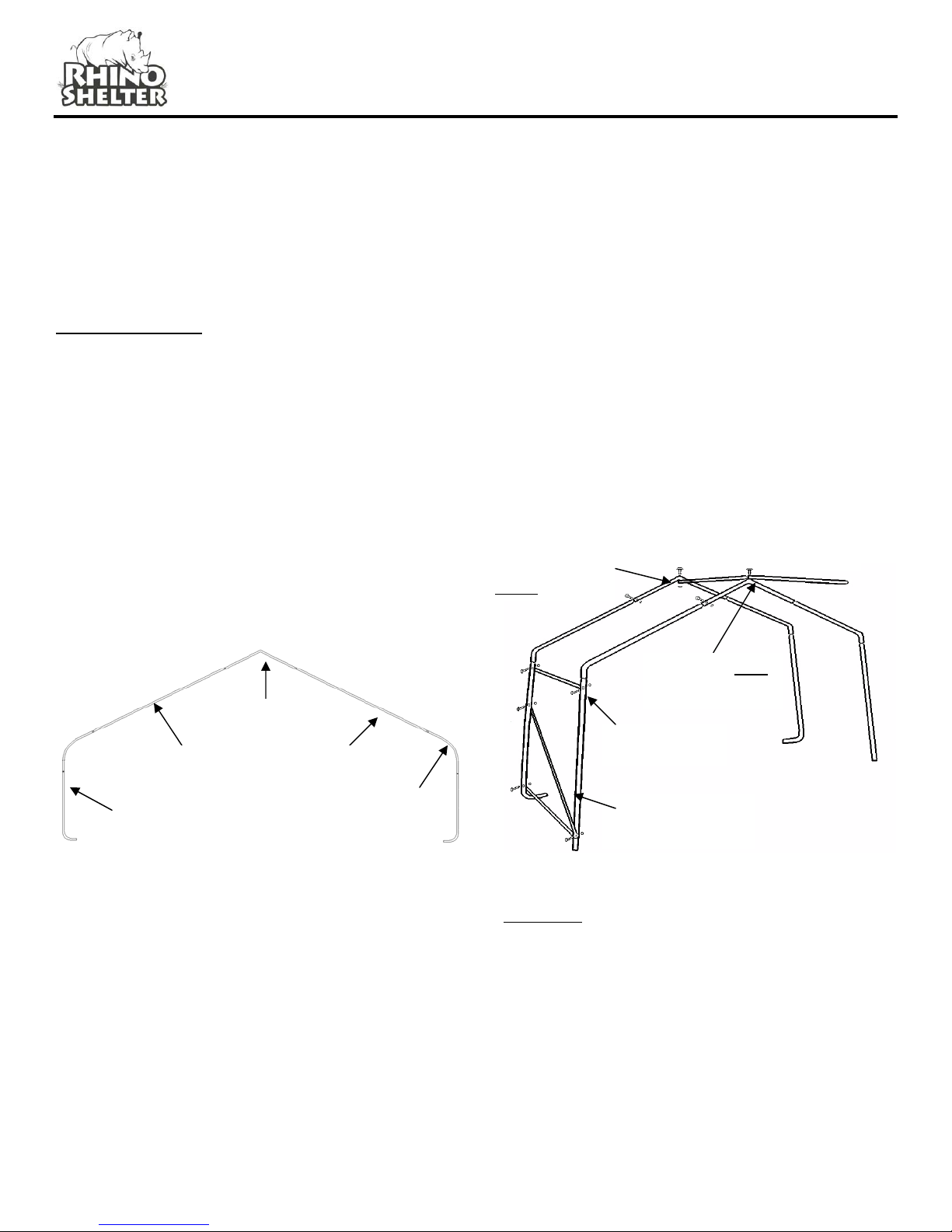
3. Assemble seven (7) arches of unit
4. Assemble unit end arch, first interior arch, and wind
braces with first base rails and side rail sections.
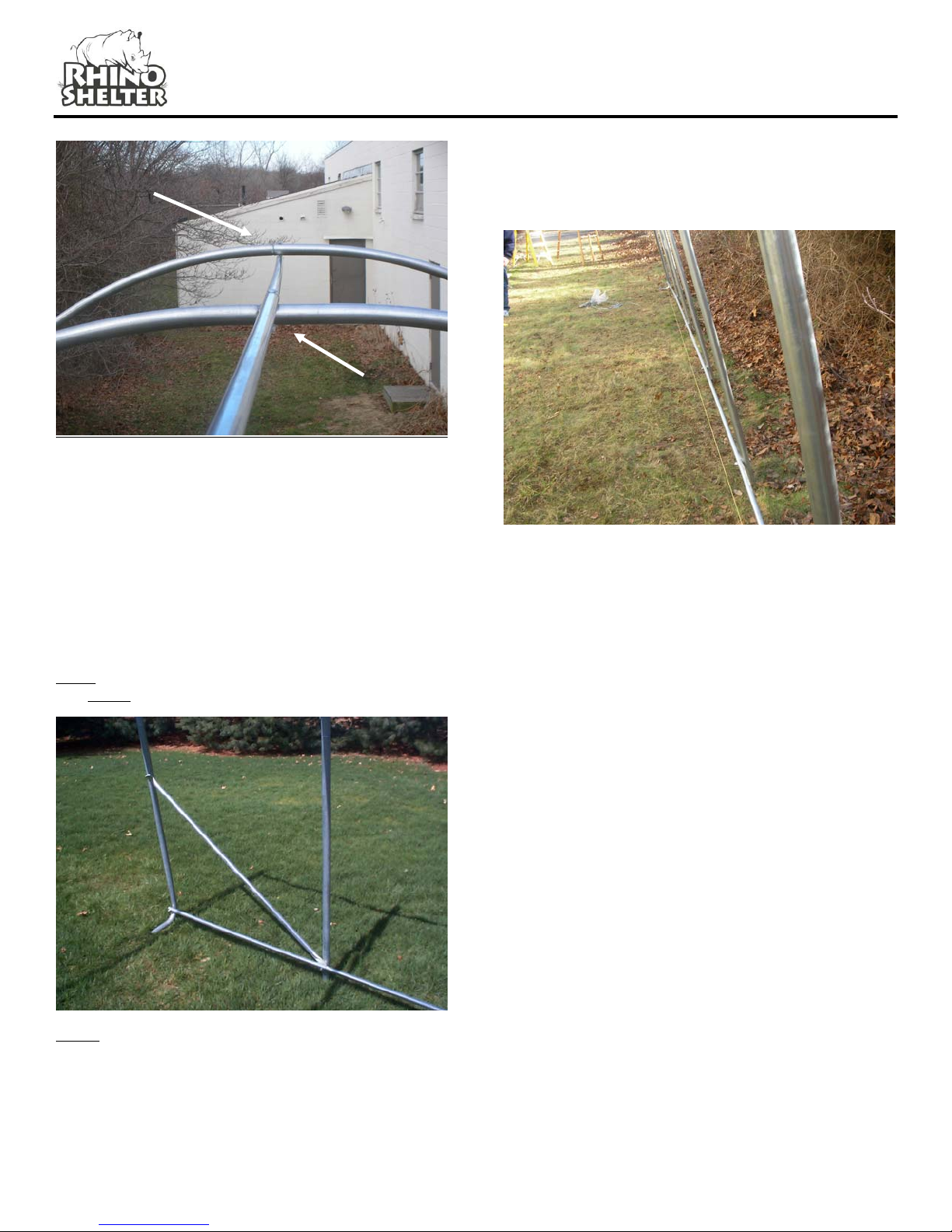
5. Add additional arch assemblies with each section of
base rails and side rails.
6. Place frame into desired position and level frame
both end-to-end and side-to-side. Measure interior
of frame feet across opposite corners and square as
needed.
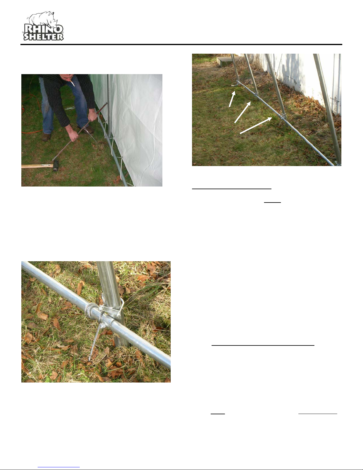
7. Anchor frame assembly firmly to ground with
anchors, u-bolts and drive rod provided.
8. Install two (2) doors on ends of frame assembly.
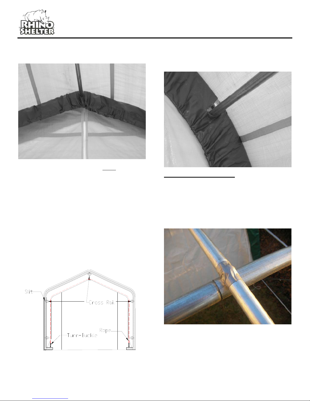
9. Install main cover over frame assembly.
TOOLS REQUIRED
The following hand tools are suggested for proper
installation of your new Rhino Shelter unit:
9/16” Open End Wrench
9/16” Socket or Box Wrench
Large Flat Tip Screwdriver
Maul or Sledgehammer
2-foot Level
10-Foot Step Ladder
INVENTORY CHECK
Start installation procedure by removing all components
from packaging and ensure all components are present
Qty Part Number Description
1 MUC-6000 Main Unit Cover
2 DZD-6002 End Panel Door with Zippers
4 EUL-6002 End Upright w/Foot
14 BTSC-6006 Bent Tube Side Crest
7 TC-6000 Top Crest Tube
10 CSU-62001 Center Straight Uprights
14 TSS-6000 Top Straight Supports
4 CW-6005 Corner Wind Brace

Assembly Instructions22x24x12 Peak Style Two Car Garage
25 SCR-2004 Swedged End Cross Rails
5 ECR-2003 Plain End Cross Rails
8 TB-3004 Turnbuckles
35 CBN-3005-4 Carriage Bolts – 4”
42 CBN-3005-
278 Carriage Bolts – 2-7/8”
77 CBN-3005-N 9/16” Nuts
69 CBN-3005-W Washers – 9/16” Cupped
8 Washers – 9/16” Flat
2 R-3003 3/16” Rope
14 DBA-3000 Earth Cable Anchors
14 UB-3002 U Bolts with Nuts
1 DR-3001 36” Anchor Drive Rod
4 EP-1000 2-3/8” Plastic End Plugs
10 EP-1001 1” Plastic End Plugs
Note: All Side & Base Cross Rails MUST be on the
inside of Arch frame members. Top Ridge Cross
Rails MUST be on the outside of Arch frame
members, except at End Arches. See Step 5 for
details.
End Arch Assembl
y
To
p
Rid
g
e Rail
Side Cross Rails
Top Straight Support
Bent Tube Side
Crest
End Upright with
Foot
Corner Wind Brace
Center Straight Uprights
Base Cross
Rails
Top Crest Tube
SITE PREPARATION
Select a level or as close to level as practical location for
your Rhino Shelter unit. The unit should be placed on a
base of materials suitable for the storage load to be
protected. The unit should not be located under trees,
which will shed hard fruit such as apples, walnuts, or
heavy pinecones. The cover of your unit will protect
against normally leaves and light debris, however large
branches or other falling items may cause puncture or
tears in the cover material.
Take notice of drainage both near and around your
intended location. Water draining from the surrounding
V2.3 2

Assembly Instructions22x24x12 Peak Style Two Car Garage
terrain should be planned so that it does not run into the
unit. As well, rain or melting snow that comes off the
unit should be drained away rather than accumulate and
pool around the unit.
Check to be certain that adequate clearance is allowed
for entry and exit from ends of unit. As unit has doors on
both ends, ideally vehicle or contents can be inserted or
removed from either end.
V2.3 3
FRAME ASSEMBLY
Step1. Assemble the Front and Rear End Arch
Assemblies (2) using (1) Top Crest Tube (TC-2000), (2)
Top Straight Supports (TS-6000), (2) Bent Tube Side
Crest (BTSC-2006) and (2) End Upright w/Foot (EUL-
2002) for each End Arch Assembly. Slide the male
(swedged) end of the frame components into the
matching female end of the next frame member. Use 2
¼” Carriage Bolts (CBN-3005-2) with washer and nuts to
assemble the arch assemblies through the pre-drilled
holes.
Be certain to insert carriage bolts from the outer edge
into the interior of the unit, with the washers and nuts on
the inside of the arches. This will avoid tearing the fabric
on doors and main cover when installed. Do not tighten
the nuts completely until the frame is completed and set
in place.
Step 2. Assemble (2) Corner Wind Braces (CW-2005) to
the End Upright w/Foot (EUL-2002) on each of the End
Arch assemblies. Use a 2 1/8” (CBN-3005-2) Carriage
Bolt with Washer and Nut to secure the braces loosely to
the Upright. Do not tighten completely.
Step 3. Assemble the remaining four Interior Arch
Assemblies using (1) Top Crest Tube (TC-2000), (2)
Bent Tube Side Crest (BTSC-2006), (2) Top Straight
Supports (TS-6000), and (2) Center Straight Upright
(CSU-2001) for each Interior Arch Assembly. Use 3¼ ”
(CBN-3005-3) carriage bolts with washers and nuts in
the pre-drilled holes, aligned to form the arch.
Step 4. Prepare the first End Arch Assembly by
supporting it temporarily in the vertical position. Connect
the (4) Plain End Cross Rails 1” diameter (ECR-2003) to
the End Arch at the base rail and side rails positions.
Use (4) 3¼” (CBN-3005-3) carriage bolts, washers, and
nuts through the pre-drilled holes in the arch members.
The Cross Rails should be put into the bottom and side
hole of the arch upright. Again, don’t tighten the
hardware until the next arch and cross rails are
assembled. It is very important to make certain all nuts
are on the inside of the unit to avoid damaging the cover
when put on.
Stand an interior arch assembly up approximately 48”
apart from the End Arch Assembly. Position it so the
cross rails from the End Arch Assembly align with the
holes in the Interior Arch. Using (4) 3¼” Carriage Bolts
(CBN-3005-3) with nuts and washers, connect the cross
rails between the end arch and the first interior arch
assemblies. Connect the (2) Wind Braces #CW-2005
diagonally across the end and interior arch as shown in
the frame illustration. Use flat 9/16” washer on the
carriage bolt for the wind braces.
Step 5. Begin the Top Ridge Rail by placing the
remaining Plain End Cross Rails (ECR-2003)
underneath the End Top Crest Tube. Secure the Cross
Rail loosely with a 3¼” Carriage Bolt (CBN-3005-3) with
washer and nut facing the interior of the unit. Place the
other end of the cross rail over the first Interior Arch as
shown in the picture below.
EUL-2002
End Upright w/Foot
TC-2000 Top
Crest Tube
BTSC-2006
Bent Tube Side
Crest CW-2005 Corner
Wind Brace
End Cross Rails
Under End Arch
Cross Rails Over
Interior Arches
Side Cross Rail
TSS-6000 To
p
Strai
g
ht Su
pp
orts

Assembly Instructions22x24x12 Peak Style Two Car Garage
V2.3 4
Step 6. Add remaining 4 Interior Arch Assemblies and
finally 2nd End Arch Assembly in sequence in the same
fashion. For each arch that is added, add a pair of base
cross rails, a pair of side cross rail and the top ridge rail
by inserting a Swedged End Cross Rail (SCR-5030) into
the prior pole end. By adding cross rails at base, side,
and top ridge, the arches will integrate into a strong
frame assembly.
At the other End Arch Assembly, be certain to install the
remaining two (2) Wind Braces (CW-6005) for stability.
Plain end of final Swedged Cross Rail should fasten
under the End Top Ridge Crest Arch and the Swedged
End above middle Top Ridge Crest arch.
NOTE: Do not completely tighten bolts that connect the
Cross Rails to the End Arches. They must be removed
for proper for End Panel Zippered Door installation
Step 7. Move the frame assembly into its final
installation location. This should be done with at least
one person lifting each frame upright to avoid bending or
stressing any frame members.
Under End
Arch
Frame should now be squared up in position. Use a
straight-line string to align all frame members on the first
side into position. Then measure and adjust each arch
end to the proper base width of 22’ to align the other
side. Finally measure diagonally from inside corner to
inside corner of frame. Both diagonal measurements
should match. Measure at each end across base of
arches. Do not expand arch width beyond 22’ wide.
This will severely reduce strength of arch assembly and
cause fabric misfit. Adjust frame and support as
necessary to bring frame into square. Failure to square
frame of unit will result in poor main cover fit and
reduced strength and rigidity. If end or interior upright
ends are placed on soft material that will not support
weight, recess small patio blocks or bricks under leg
ends. This will also allow better setting of frame before
securing to ground.
Over
Interior Arch
Align each
Arch with
string to make
edge of Frame
STRAIGHT
before securing
Wind Brace
Across End
Arch and
Interior Arch
Assemblies

Assembly Instructions22x24x12 Peak Style Two Car Garage
V2.3 5
Step 8. Once frame is square and properly supported,
tighten carriage bolts on all frame members, except for
End Arch members to Cross Rails along base, side, and
top. After hardware is tightened, insert plastic end plugs
2-3/8” EP-1000 & 1” EP-1001 into all open ends of frame
members.
ANCHORING FRAME TO GROUND
Once frame is square and properly supported, tighten
carriage bolts on all frame members, except for End
Arch members to Cross Rails along base, side, and top.
Do not over tighten or oval tubing. After hardware is
tightened, insert plastic end plugs #14 (2 3/8”) & #15 (1
1/8”) into all open ends of frame members.
NOTE: Frame must be anchored before
installing any doors or cover.
Each Rhino Shelter 22x24x12 building comes with 14
EARTH CABLE ANCHORS with U-bolts and nuts.
These versatile anchors allow the frame to be secured to
almost any surface. In addition you have also been
provided with a 36” Drive Rod used to drive the anchor
heads into the earth.
If the location where you are placing the building has
very hard ground or any rock in it, pre-drill the holes
before inserting anchors. Hammer drills can be rented
at most home improvement or rent-all centers. Hitting
the anchors into rock will cause the drive rod end to
mushroom inside the anchor head, and prevent the drive
rod from coming out of the hole.
Anchor placement should be made inside the frame at
the interior corners of the unit, and midway along the
sides of the frames. Anchors secure the building to the
ground, as well as prevent spread of the frame over
time.
Support Each
Upright on a
Solid Base
Pre-Drill Holes if there is Any Rock In Ground
Drive Rod inserts into Anchor Head
ANCHOR STEP 1
Step 1. Place the drive rod provided into the cup of the
anchor. Using a heavy hammer drive the anchor into the
soil until 6-8 inches of cable remains above the earth.
Remove drive rod.
ANCHOR STEP 2

Assembly Instructions22x24x12 Peak Style Two Car Garage
Place the Drive Rod through the loop in the anchor
lanyard. Pull upward to set anchor head into the ground.
V2.3 6
ANCHOR STEP 3
Slip one side of the U-bolt through the eyelet at the end
of the anchor cable. Attach the cable to the Arch leg
upright with the U-bolt and tighten. Do not attach to base
cross rails. Ensure there is no slack in the cable. Slack
can be removed by wrapping the cable around the tie-
down rail.
EVERY
Arch
Upright
MUST be
anchored
END PANEL INSTALLATION
Note: Both End Panels MUST be installed before
installing Main Cover onto frame.
Step1. Install One (1) End Panel Door w/Zippers (DZD-
6002) at a time to ends of the Frame assembly.
Remove Carriage bolts from the Top Ridge Rail, the two
Base cross rails, and the two side Cross Rails.
Step 2. Place the end panel over the door over end
arch and wrap the material around the arch bringing the
vertical slits in the end panel to the inside of the frame
arch. End Door Panels have pre-cut slits that allow
frame members to pass through so rope pocket is inside
unit. Place the top rail ridge pole and the side cross rails
through the material slits and replace the carriage bolts
and tighten. The door end will also require removal of
the wind brace bolts and placement of the wind braces
through slits in the ends panel. Reconnect wind braces
with carriage bolts once end panel is put into place.
Wrap Excess
Cable around
Frame
Member to
Draw Anchor
Connection
Tight
When putting on the doors, adjust the length to make
certain the doors do not drape onto the ground. Adjust
by pulling more or less material over the end arch
assembly. If pulling them up puts too much stress on
the slit where it goes over the wind brace, use a sharp
knife to cut slit another inch or two to relieve it. The PE
fabric is rip-stop weave, and can easily be cut to relieve
stress at the frame members.
Door assembly is drawn over frame by tightening rope
and securing to turnbuckles at the arch foot (Step 3).
Frame must be secured in position so it does not move
as end doors and main cover are tightened over frame.

Assembly Instructions22x24x12 Peak Style Two Car Garage
This step is key to good fit and to prevent door
movement in wind.
The rope channels should be located inside the unit, with
the frame members passing through the pre-cut slots in
the end panel/door. Replace and tighten the carriage
bolts after putting the end panel into position.
V2.3 7
Step 3. Tie off one end of the rope coming out of the
end panel to a turnbuckle. Turnbuckle should be
loosened all the way and the open hook end attached to
the hole in the inside of the end arch foot. Hold the end
of the unsecured rope and apply pressure downward
with a foot to remove excess. Re-adjust gathered
material evenly along door rope. This step is key to
getting a good door fit. Tie off the end off the rope to a
second turnbuckle attached to a hole in the foot of the
end arch on the opposite side. The end panel can be
adjusted further by tightening the turnbuckles.
Note: Adjust/Snug the end panel by turning the
turnbuckles or repeating step 3 on a regular basis
MAIN COVER INSTALLATION
Step 1. To elongate the life of Main Cover, put a small
square of duct tape (field supplied) over each bolt head
on frame that comes in contact with cover. The tape
acts as a cushion to avoid rubbing damage to the cover
over years. As an alternative, foam rubber pipe
insulation also makes a good cushioning material over
frame parts.
Unpack the Main Cover #MUC-7000 from the protective
plastic packaging. The line of grommets on the inside
(white) of the cover on the tie down Flap run parallel to
the sides of the frame assembly for positioning. Once
cover is oriented parallel to the side of the Frame

Assembly Instructions22x24x12 Peak Style Two Car Garage
Assembly (lengthwise), lift Main Cover edge over frame
assembly from the side, being careful not to snag the
cover on any member, bolt, or other obstruction. Center
the Main Cover over the Frame Assembly with the Main
Cover colored side showing from the outside of the unit.
Step 2. Loosen the 4 remaining turnbuckles completely.
Place the turnbuckles into outer hole in the foot of each
end arch. Tie off the rope coming out of the Main Cover
rope slot on either side to the turnbuckles. After
securing one end of the rope in the Main Cover, pull the
excess slack out of the rope and cover to tighten. Hold
the end of the unsecured rope and apply pressure
downward with a foot to remove excess. Temporarily tie
the end of the rope to the turnbuckle. Go over the entire
outer edge of the cover and adjust the excess material
around the end so it is not bunched up. Spread excess
material evenly along the outer edge. Once cover is
pulled tight and even, tie off the rope end to the
turnbuckle. All slack should be out of the rope at this
time. Repeat this step on both ends of the cover.
Tighten the turnbuckle to tighten the cover. This step
may need to be repeated to ensure a snug and centered
fit.
Step 3. When the cover is completely aligned secure
the cover to the bottom tie-down cross rail using the rope
provided. Start at one end and tie off the rope to the
cross rail. Lace the rope through the grommets in the
cover and back under the tie-down cross rail. Repeat
this on the opposite side
V2.3 8
Pay close attention to how tight the cover is put onto the
frame. It should be tight enough so it does not flap
around in the wind, but not so tight that it tears the
material cover. The fabric backed PE fabric of Rhino
Shelter units does not stretch. If you pull it so tight that
the fabric is stretched, a small amount of additional
stress from wind or contact can cause premature tears
and failure. Only tighten cover enough to remove
valleys between arch assemblies. Do Not over tighten.
Step 4. Retighten the turnbuckles on both the cover and
end panels. Retighten the rope holding the main cover
to the bottom cross rail. Both the cover and the end
panels should be checked and tightened on a
monthly basis.
Roll Up Door Kits are included standard for triple zipper
doors on one end of your Rhino Shelter 22X24X12 unit.
Refer to the Roll Up Door Kit Installation Instructions for
proper installation. These should be installed only after
complete installation of doors and main cover. For best
operation and fit, install the Roll Up Door Kits after a few
days and making adjustment to cover as needed.
MAINTENANCE AND CARE
Annually or more often, the unit should be completely
inspected internally and externally to make certain the
unit remains properly installed and secured. Particular
attention should be paid to:
Hardware – check all carriage bolts and hardware
connectors to be certain they are in place and tightened.
Anchors – during normal weather trends, the unit will
strain against the anchors under windy conditions.
Anchor hardware connection to frame members should
be maintained tight and depth of anchors should be
checked to be certain they remain deeply and firmly set.
Snow Accumulation – All snow accumulation on the
main cover should be removed as soon as possible.
Tap the main cover from the inside with a broom or soft
brush to clear cover. Unit is not designed for any
amount of accumulated snow or ice. Warrantee does
NOT cover damage due to snow accumulation.

Assembly Instructions22x24x12 Peak Style Two Car Garage
V2.3 9
Main Cover Lacing – the poly rope that secures the main
cover to the bottom rail of the frame assembly should be
checked, and adjusted as needed. The tension on the
main cover should be uniform from end to end and side
to side. Rope ends must be tied off onto the frame
members at the ends on each side.
Turnbuckle Adjustment – during normal wind conditions
and load, the doors and main cover adjustment points at
the turnbuckle should be checked and tightened as
necessary. The turnbuckles should be neither
completely extended nor taken up, so that turnbuckle
should be tight when in the mid range of overall
adjustment. If necessary, readjust rope tie off on
turnbuckle as needed to tighten or loosen as needed.
Cleaning – cover and doors can be cleaned with a
mixture of light detergent and water. A soft bristle brush
with the mixture can be used to loosen any hard dirt,
mold, or buildup on the cover. After cleansing, the cover
should be rinsed thoroughly to avoid any chemical
reaction from residual detergent. Allowing dirt and
debris to sit on cover over an extended time will damage
cover irreparably.
Severe Weather – in preparation for inclement weather,
completely secure the doors on both ends of your Rhino
Shelter portable building. Allowing windto enter either
end lifts the building and puts undue stress on the
anchoring system. This also shortens the life of the
doors, zippers, and main cover.
Door Operation – Every timedoors are put down the
zipper must be pulled down completely. Failure to do so
will cause door zipper to fail prematurely.
CUSTOMER SERVICE & ASSISTANCE
Care and attention to a proper installation will add many
years of life and function to your Rhino Shelter unit.
Please retain purchase documentation for your Rhino
Shelter unit. All warranty claims must include purchase
documentation for verification. All parts on your Rhino
Shelter unit are available for replacement as needed.
Protect your purchase by completing warranty
registration card and mail/fax as soon as practical after
installing your unit.
Thanks again for choosing this quality product. With
proper operation and care we are confident it will meet
your expectations in functionality, appearance and
longevity.
Check out the collection of covers world we offer.
Table of contents
Other Rhino Shelter Tent manuals