RT-1000 MC DF-Channel
RHOTHETA Page 3 of 27 User Manual
Content
1
Description.......................................................................................................................5
2
Front View ........................................................................................................................5
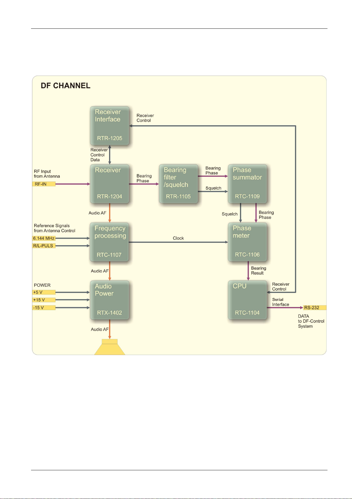
3
Block Diagram and Component Description.................................................................6
4
Control Elements.............................................................................................................8
5
Rear View..........................................................................................................................9
6
Functional Descriptions................................................................................................12
6.1
Switching on the DF-Channel...............................................................................................................12
6.2
Switch-on Reaction, Operation, Control Equipment.............................................................................12
6.3
Receiver Self-Test................................................................................................................................12
6.4
Power Supply OK Control LED.............................................................................................................12
6.5
Control Data Transmission...................................................................................................................12
6.6
Squelch Control LED “Sql” ...................................................................................................................12
6.7
Bearing Indication.................................................................................................................................12
6.8
∆f-, ∆f+ Deviation Recognition Control LEDs.......................................................................................13
6.9
Control LED “No Sync”.........................................................................................................................13
6.10
“IF” Intermediate Frequency Jack.........................................................................................................13
6.11
Remote / Local Switch..........................................................................................................................13
6.12
“Level-Frequency-QDR” Switch............................................................................................................13
6.13
Frequency Selection key ▲/▼.............................................................................................................13
6.14
Squelch adjustment potentiometer.......................................................................................................13
6.15
Phase Adjustment.................................................................................................................................14
6.15.1
Adjustment Using RTM 1500 Antenna Model (Option)..........................................................14
6.15.2
Adjustment Using a Transmitter.............................................................................................14
6.16
Error Indication .....................................................................................................................................15
6.17
"Sync" Synchronisation Indicators........................................................................................................15
6.18
"DF Signal 2" Test Plug........................................................................................................................15
6.19
"R/L" Test Connector............................................................................................................................15
6.20
Serial Interface......................................................................................................................................16
6.21
Data Output ..........................................................................................................................................17
6.22
Data Input .............................................................................................................................................19
7
Electrical Parameters ....................................................................................................22
7.1
Power Supply........................................................................................................................................22
7.2
DF-Signal 2 and R/L.............................................................................................................................22
7.3
Reference Signals Input .......................................................................................................................23
7.4
Pegel- Output........................................................................................................................................24