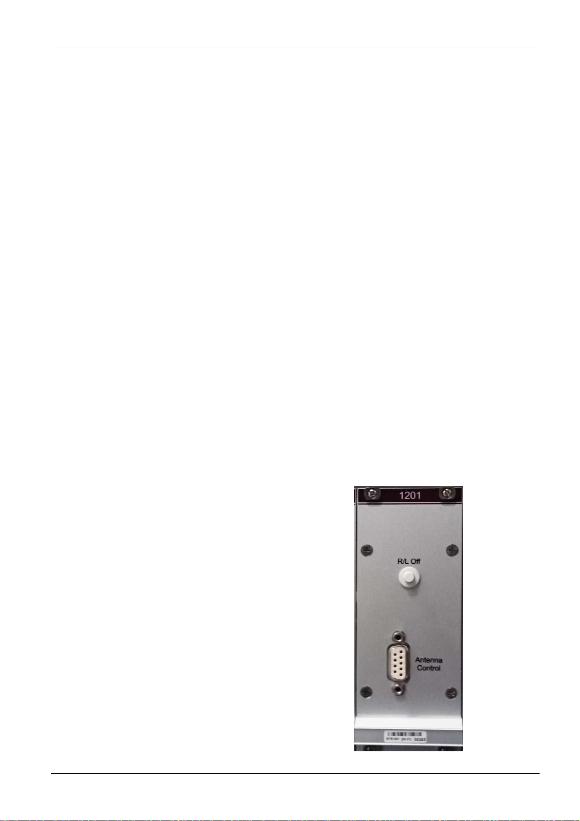
RT-1000 Antenna Control
RHOTHETA Page 7 of 10 User Manual
5.2 Backplane Interfaces
X1 -- -- Internal connection
X2 1 -15 V DC Supply Input -15 V
2 +15 V DC Supply Input +15 V
3 +5 V DC Supply Input +5 V
4 GND DC Supply Input Ground
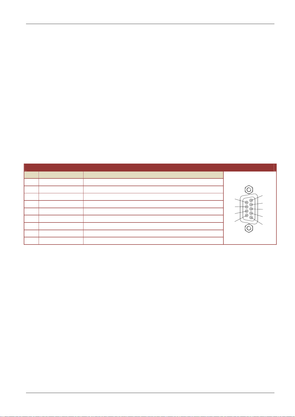
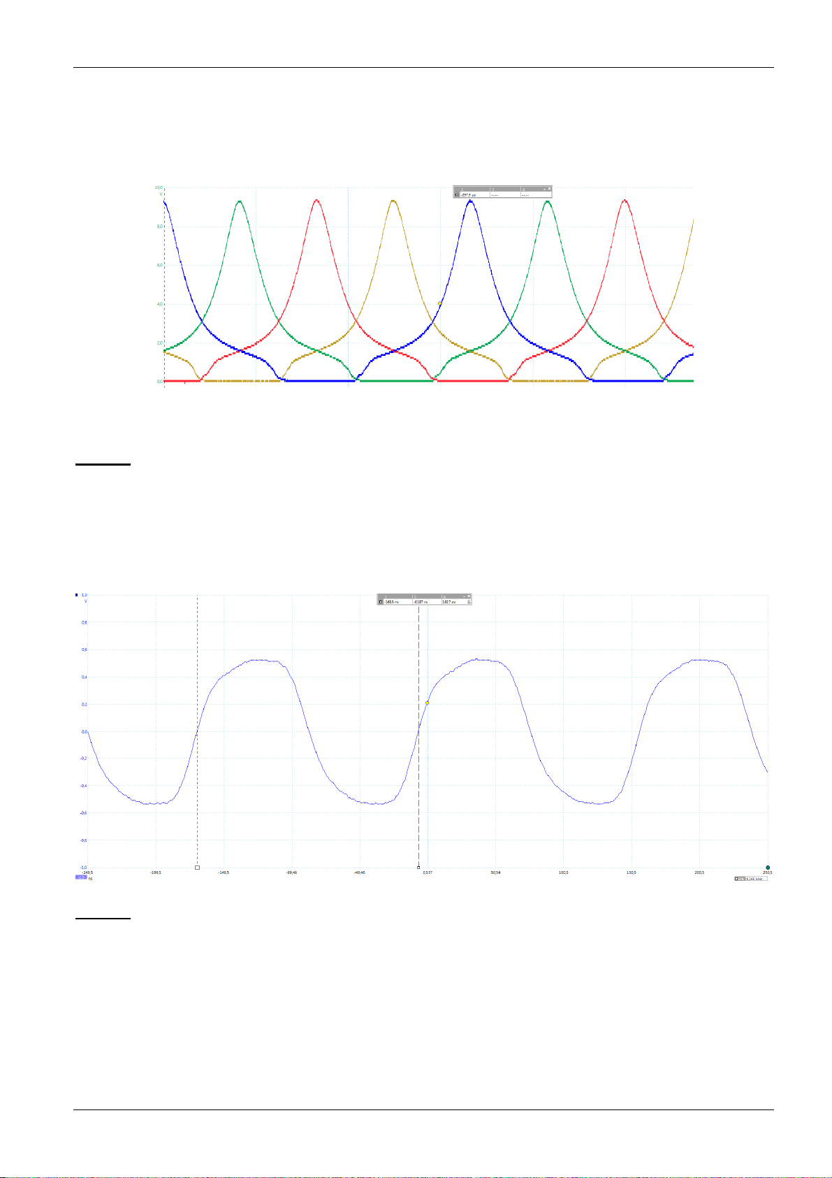
X3 1 WEST Antenna Control Signal, West
2 EAST Antenna Control Signal, East
3 SOUTH Antenna Control Signal, South
4 NORTH Antenna Control Signal, North
5 +15 V Antenna Control Signal, +15 V
6 GND Antenna Control Signal, Ground
X4 -- R/L-PULS-1 Reference Signal R/L Pulse
X5 -- R/L-PULS-2 Reference Signal R/L Pulse
X6 -- R/L-PULS-3 Reference Signal R/L Pulse
X7 -- R/L-PULS-4 Reference Signal R/L Pulse
X8 -- 6144KHZ-1 Reference Signal 6,144 MHz
X9 -- 6144KHZ-2 Reference Signal 6,144 MHz
X10 -- 6144KHZ-3 Reference Signal 6,144 MHz
X11 -- 6144KHZ-4 Reference Signal 6,144 MHz
X12 1 ROT-OFF-1 ON/OFF Antenna Control Signals, Channel 1
2 GND ON/OFF Antenna Control Signals, Channel 1 Ground
3 ROT-OFF-2 ON/OFF Antenna Control Signals, Channel 2
4 GND ON/OFF Antenna Control Signals, Channel 2 Ground
X13 1 ROT-OFF-3 ON/OFF Antenna Control Signals, Channel 3
2 GND ON/OFF Antenna Control Signals, Channel 3 Ground
3 ROT-OFF-4 ON/OFF Antenna Control Signals, Channel 4
4 GND ON/OFF Antenna Control Signals, Channel 4 Ground
X14 1 ROT-OFF-5 ON/OFF Antenna Control Signals, Channel 5
2 GND ON/OFF Antenna Control Signals, Channel 5 Ground
3 ROT-OFF-6 ON/OFF Antenna Control Signals, Channel 6
4 GND ON/OFF Antenna Control Signals, Channel 6 Ground
X15 1 ROT-OFF-7 ON/OFF Antenna Control Signals, Channel 7
2 GND ON/OFF Antenna Control Signals, Channel 7 Ground
3 ROT-OFF-8 ON/OFF Antenna Control Signals, Channel 8
4 GND ON/OFF Antenna Control Signals, Channel 8 Ground