Rhotheta RT-1000 User manual

User Manual
RT-1000
Antenna Mast

RT-1000 Antenna
RHOTHETA Page 2 of 17 User Manual
Edited by:
RHOTHETA Elektronik GmbH
Kemmelpark
Dr.-Ingeborg-Haeckel-Str. 2
82418 Murnau
Germany
Tel.: +49 8841 4879 - 0
Fax: +49 8841 4879 - 15
Internet: www.rhotheta.de
E-Mail: [email protected]
Copyright © RHOTHETA Elektronik GmbH
All rights reserved
-Issue: 2016/01/28 [Rev 1.00]
-Document-ID: 12-9-1-0015-10-4-3-60
Note
The manufacturer reserves the right to make modifications at any time and without previous
information of the here described product.

RT-1000 Antenna
RHOTHETA Page 3 of 17 User Manual
Content
1
General Description.........................................................................................................4
2
Part List ............................................................................................................................5
3
Assembly of the Mast......................................................................................................6
4
Installation........................................................................................................................7
5
Functional Descriptions................................................................................................12
5.1
Tilting of the Mast .................................................................................................................................12
5.2
Rotating of the Direction Finder Antenna .............................................................................................12
6
Base................................................................................................................................13
6.1
Mounting of the Masts to their Base.....................................................................................................13
7
Lightning Rod / Grounding...........................................................................................16
8
Mechanical Data.............................................................................................................16
9
Notes...............................................................................................................................17

RT-1000 Antenna
RHOTHETA Page 4 of 17 User Manual
1 General Description
The antenna mast is a girder mast which has been developed especially for the Doppler
antenna system RTA 1300, which makes possible the turning and titling of the antenna for
assembly and maintenance purposes. The mast will be delivered in disassembled condition. It
has to be mounted and grounded after the assembly on a suitable base. The scope of
delivery also includes a waterproof installation box, in which the receiver unit and remote data
transmission or the lightning protection can be located. All parts of the mast and the bolted
connections are hot-dip galvanized or respectively made out of stainless steel.

RT-1000 Antenna
RHOTHETA Page 5 of 17 User Manual
2 Part List
Part List
Pos
.
Component
Number
1 Support Tube 4
2 Base Plate (bottom) 1
3 Support Tube Clamp (pre-assembled) 5
4 Cover Plate (above) 1
5 10° Step Angle Disk with Tilting Joint 1
6 Vertical Brace (l = 600) 2
7 Vertical Brace with Fixed Clamp (l = 600) 1
8 Cross Brace (l = 1200) 8
9 Suspension Brace (l = 450) 8
10 Mast Tube 1
11 Lever 1
12 Clip 1
13 Screw M 10 x 30 22
14 Screw M 10 x 35 8
15 Fitting Screw (for Lever) 1
16 Nut M 10 30
17 Disk for M 10 60
18 Screw M 8 x 25 4
19 Screw M 8 x 30 6
20 Screw M 8 x 40 8
21 Nut M 8 34
22 Disk for M 8 48
23 Screw M 6 x 30 4
24 Nut M 6 1
25 Disk for M 6 5
26 Installation Box / Antenna Cabinet 1
27 Sun Shade for back an side part of the Installation Box 1
28 Sun Shade for top face of the Installation Box 1
29 Protective Hose 1
30 Bolting of the Protective Hose 1
31 Rubber Joint 1

RT-1000 Antenna
RHOTHETA Page 6 of 17 User Manual
3 Assembly of the Mast
After unpacking and comparing the supplied parts to the list of parts, the assembly can be
done. If you want to assemble the mast in a closed room, you should make sure that doors
and windows are large enough to transport the assembled mast out of the room. We
recommend preparing items which are included in the scope of supply, e.g. sealing silicone
and tools, before starting the assembly. You need two persons for the mast mounting.
Additional Items Required
Pos.
Component
Number
1 Drill machine --
2 Felt tip pen or similar --
3 10 mm drill for steel 1
4 wrench MW 1O 1
5 wrench MW 13 2
6 wrench MW 17 2
7 wrench MW 19 1
8 wrench MW 22 1
9 Silicone sealing material --
The mast has to be mounted in a horizontal position and can only be positioned after the
assembly. The screws are initially hand-tightened. The tightening is done after completion of
installation and positioning.
For the assembly of the mast frame, please make sure to use the corresponding screws with
a diameter of 10 mm and the corresponding disks.
The braces designated in the text as “vertical braces” are about 600 mm long; they connect
the support tubes directly. The cross braces are approximately 1200 mm in length and
connect the support tubes crosswise. Suspension braces are approximately 450 mm long and
are used to fix the mast base.

RT-1000 Antenna
RHOTHETA Page 7 of 17 User Manual
4 Installation
Installation Procedure
Step
Description
Figure
1
Set the four support tubes according to Figure 1
on the ground. The two supporting tubes with the
fixing clamps for the installations box have to be
set mirror reversed to each other on the floor. The
two other support tubes have to be set in the same
way, also the mirror reversed.
Figure 1: Lining up of support tubes
2
Connect the two support tubes (with the fixing
clamps) with the aid of the vertical brace, which
also has clamps for fixing the installation box.
Make sure that the vertical brace, which is
“outside” the mast, is directed towards the end of
the mast or inwards. All fixing clamps for the
installation box are now parallel to each other.
3
Now you have to fix the two cross braces
according to the Figure 2. The cross braces have
to be mounted on the fixing clamps on the "outside
of the mast". For the fixing clamps on the mast
foot, you have to use the upper holes.
Figure 2: Lining up of support tubes

RT-1000 Antenna
RHOTHETA Page 8 of 17 User Manual
Installation Procedure
Step
Description
4
The second couple of support tubes has to be treated similarly; however, you don't
have to mount a cross brace to permit a tilting of the mast tube for mounting the
antenna.
Figure 3
5
Now you have to install the remaining vertical and cross braces on one of the support
tube pairs. These are bolted to those fixing clamps on the support tubes, which are
perpendicularly fixed to the fixing clamps of the already attached braces.
Figure 4

RT-1000 Antenna
RHOTHETA Page 9 of 17 User Manual
Installation Procedure
Step
Description
Figure
6
You next put the second support tube pair
congruent on the pair with the already assembled
brace with the "internal side" towards each other
(Figure 3). The two support tube pairs are now
connected. Therefore, one person raises the
upper support tube pair at the open end until the
two vertical braces can be connected with the
corresponding fixing clamps (Figure 4). Do the
same with the cross braces (Figure 5).
Figure 5
7
Now you can attach the cover plate. The clamps
are already preassembled on the top plate. The
top plate has a cut-out for the mast tube, which
has to point away from the support tube pair with
the fixing clamps for the installation box. Now you
can open the clamps completely and move them
over the lower support tube pair. To bring the
upper support tube pair into the clamps, you have
to impose light pressure upon the support tubes.
Make sure, that the supporting tubes are really
flush to the cover plate (Figure 6) and then close
the clamps.
Figure 6

RT-1000 Antenna
RHOTHETA Page 10 of 17 User Manual
Installation Procedure
Step
Description
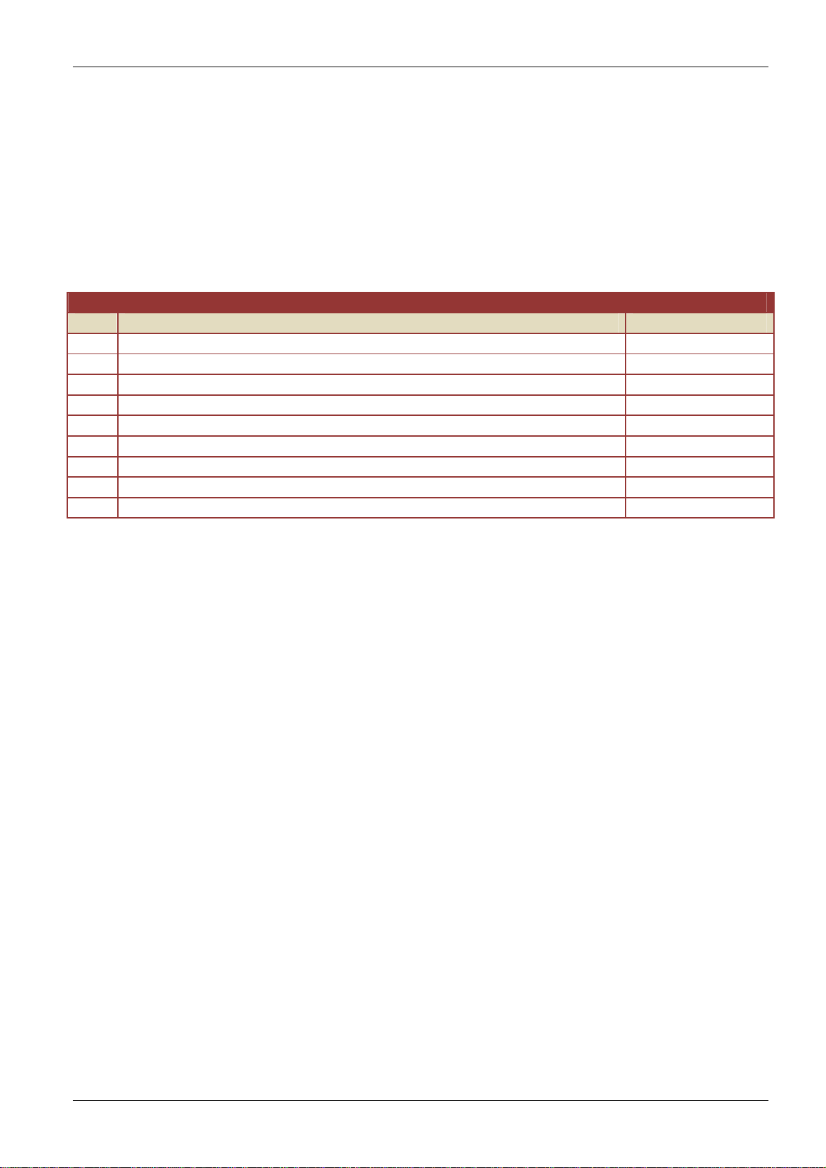
8 Now the mast can be installed on the flat ground. All screws have to be tightened.
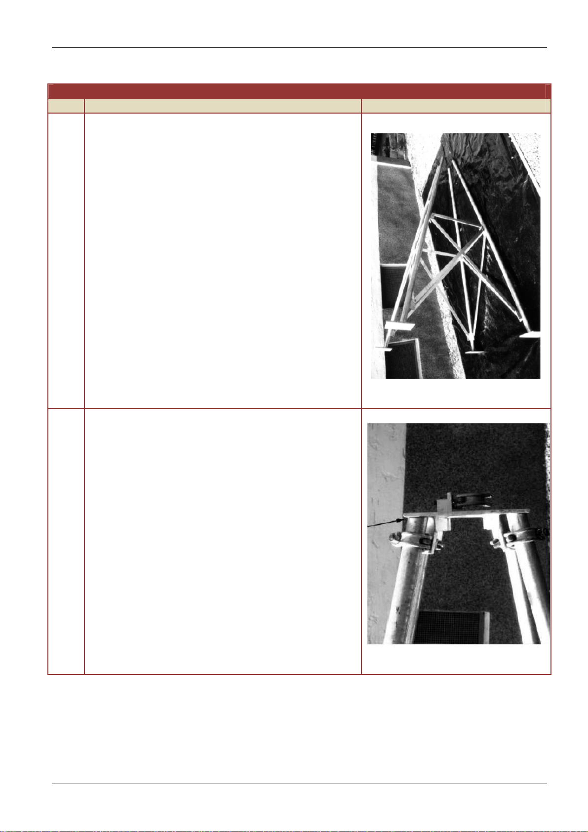
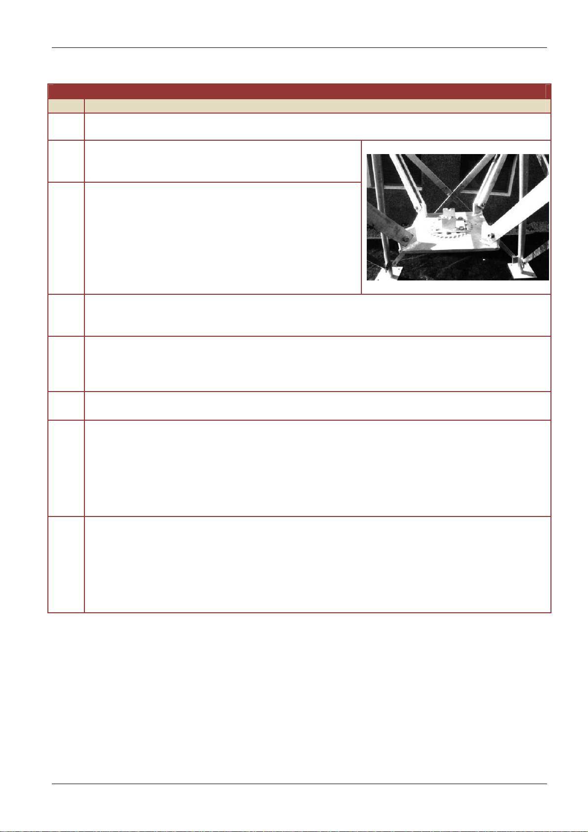
9 The eight suspension braces for the mast foot
plate needs to be installed now on the fish plates,
which have remained free (Figure 7).
Figure 7
10
You now screw the preassembled mast foot plate
(see drawing "mast") to the suspension braces.
You need to make sure that the hole for the lever
of the angular adjustment turns away from the
mounting of the installation box (Figure 7).
11 Open the loose clamps for the mast foot and assemble the mast. The cut at the mast
foot has to face towards the installation box. The mast needs to be loosely attached in
the gripper clamp, and then screw the clamp.
12
The installation box needs to be put between the provided fixation clamps. It should be
cantered and parallel to the mast tube and should have a distance of 60 mm to it. After
that, you have to mark the holes through the holes of the fixing clamps on the
installation box.
13 With the installation box removed out of the mast, drill the previously marked holes
with a 10 mm drill bit.
14
You have to create a breakthrough in the flange of the installation box to carry out the
data and power supply underground cable. We recommend to route the cable from the
exit site in the ground to the installation box through a galvanized steel pipe (42, 4 x
3,5mm). The steel pipe should be interred 30 cm under the ground and on the other
side you have to affix it with the aid of the rubber joint to the flange plate (see drawing
“mast base”). An appropriate rubber joint is included. The point, on which the cable
should be routed through the flange plate, is already marked on the flange plate.
15
You now have to mount the installation box with the supplied screws M8 x 30. The
screws, which connect the control cabinet to the holding brace, have to be bolted with
lock washers (on the side of the control cabinet). To assure a good ground connection
to the switchbox and the mast, the contact surface of the screws has to be cleaned
from paint. Before final tightening of the screws, they have to be sealed with UV-
resistant silicone (such as roofer usually use). Any inaccuracies can be compensated
by bending the fixation clamps or by shimming of the corresponding washer.

RT-1000 Antenna
RHOTHETA Page 11 of 17 User Manual
Installation Procedure
Step
Description
16
Now you have to fix the sun shades with the
supplied screws M8 X 40. First the screws are
bolted from the inside to outside. You'll use 2
washers per screw and seal them with silicone
before tightening. On each screw sticking out from
the casing, you have to put a washer at distance/
intervals of 20mm. Attach the sun shades and the
washers and screw them together (Figure 8).
Figure 8
17
After installation of the mast at the site, protect the cable running from the antenna to
the installation box with the supplied protective tube. Mount the gland for the protective
tube into the bottom flange in the control cabinet. Then you have to put the protective
tube in it, and the other side should be shifted 30mm into the mast tube. At the lowest
point of the protective tube, you have to drill a hole to drain possibly occurring
condensation.
Caution
During installation, the antenna cable has to be pulled from the control cabinet through the
protection tube and the antenna tubes before it will be connected to the antenna.
(Round plug does not fit through the protective tube

RT-1000 Antenna
RHOTHETA Page 12 of 17 User Manual
5 Functional Descriptions
An appropriate location of the antenna is prerequisite for the proper function of the direction
finder, which precludes possible disturbing reflections by surrounding buildings, forest or
geographic circumstances.
5.1 Tilting of the Mast
To avoid damage to the sensitive antenna beams, you
can turn the mast tube for assembly and maintenance
through 90°. Then the whole antenna head is
accessible. Therefore, the four terminal screws of the
tilting joint have to be loosened and the upper mast
clamp has to be opened. To avoid a sudden tilting of
the mast, the mast tube should already be held during
opening procedure of the clamp by a second person.
When folding back, it is imperative to ensure that the
antenna cables are not jammed (see Figure 9).
Figure 9
5.2 Rotating of the Direction Finder Antenna
To check the direction finder after assembly, the
antenna can be rotated at 10° increments. This
requires that the four lock bolts of the 10° step
angle disk are removed and the clamp holding the
upper mast pipe is loosen as far as a rotation of
the mast tube is possible. After that, the lever with
spring has to be attached on the special screw.
The mast tube can be rotated whereupon the lever
catches the step angle disk in 10° increments. The
connection cable to the antenna must not be
stretched by turning too far (Figure 10). Should the
mast tube rotate only with difficulty, or even not at
all, the four screws on the bottom clamp of the
mast tube holder should be eased.
Figure 10
Caution
You have to control if the four fixing bolts of the 10° step angle disk are tightened and if the
four screws of the clamps are loosened.

RT-1000 Antenna
RHOTHETA Page 13 of 17 User Manual
6 Base
The base for antenna mast RTA-l306 C consists of 4 single concrete bases. The floor plates
of the antenna mast will be fixed on these concrete bases by screwed anchors. The bases
can be produced by using concrete pipe tubes (DIN 4032 or similar) of at least 30 cm inner
diameter and 1 m length as permanent shuttering. There must be a cluster from concrete, at
the lower side of the tube, in order to prohibit the base socket from rising in case of frost.
Reinforcement from steel needs to be planned for so the cluster will not break away from the
tube’s concrete filling. Furthermore, wrap the concrete tube down to the freezing level with
roofing cardboard. The base sockets should protrude for some cm above ground; they have
to be flush at their upper side and must end at identical heights, so the Antenna Mast will
stand upright. The water level should be checked and adjusted if necessary. The position of
each base socket should be observed exactly so the mast feet will stand completely on its
socket and the screwed anchor can be tied into the concrete filling. If this should cause
difficulties, due to structurally engineered reasons, please plan for bigger tubes.
6.1 Mounting of the Masts to their Base
a) Place the mast cantered to the base. Adjust with water level and – if needed – spacers.
If an armoured conduit has been planned to protect the long-distance transmittal cable,
the mast has to be aligned to this.
Caution
The mast has to be positioned so that the installation box’s rear side will show towards
south (protection against sun).
b) Drill through mast foot’s holes with a driller appropriate for concrete (fitting for the
concrete anchors), and tighten the mast by screwing.
c) Adjust grounding clamps according to figure and connect with grounder by a steel wire,
diameter 10 mm DIN 48 801.

RT-1000 Antenna
RHOTHETA Page 14 of 17 User Manual

RT-1000 Antenna
RHOTHETA Page 15 of 17 User Manual

RT-1000 Antenna
RHOTHETA Page 16 of 17 User Manual
7 Lightning Rod / Grounding
For grounding, dig a hot zinc dipped strip iron (30 x 3.5 mm) of 10 – 15 m length approx. 1 m
deep into the ground. Pay attention that the strip iron will not be affected by field work or
ground moving especially in agricultural areas. Normally a cable channel has to be provided
for power connection and data cables; therefore, it might make sense to install the grounding
strip in the same cable channel. Take care that the strip iron will be separated from the cables
by a layer of sand of minimum 10 cm. The grounding strip’s exit is marked in the plan. The
strip iron has to protrude 20 cm above the base’s upper edge. After setting up of the mast,
connect the grounding strip to the mast by a lightning rod wire (diameter 10 mm).
8 Mechanical Data
Dimensions and Weight
Pos
Parameter
Value
1 Base (L x B) 142 cm x 142 cm
2 Height Mast 280 cm
3 Height Mast with Antenna 570 cm
4 High Antenna Basis 410 cm
5 Weight 120 kg

RT-1000 Antenna
RHOTHETA Page 17 of 17 User Manual
9 Notes
Other manuals for RT-1000
7
Table of contents
Other Rhotheta Marine Radio manuals
Popular Marine Radio manuals by other brands

Kongsberg
Kongsberg cNODE Mini LF 7000 m instruction manual

NorthStar
NorthStar Explorer 710 VHF Operation and installation manual

Uniden
Uniden HH985 user guide

Simons Voss Technologies
Simons Voss Technologies TRA.G2.FSR quick guide

Funke
Funke TRT800A-OLED Operation and installation

tron
tron SART Instrument manual