RT-1000 MC Maintenance Manual
RHOTHETA Page 9 of 20 Maintenance Manual
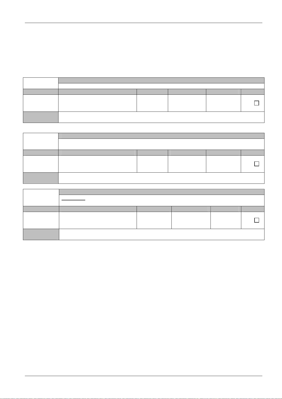
2.4 DF-Channels
2.4.1 Display and Control Elements
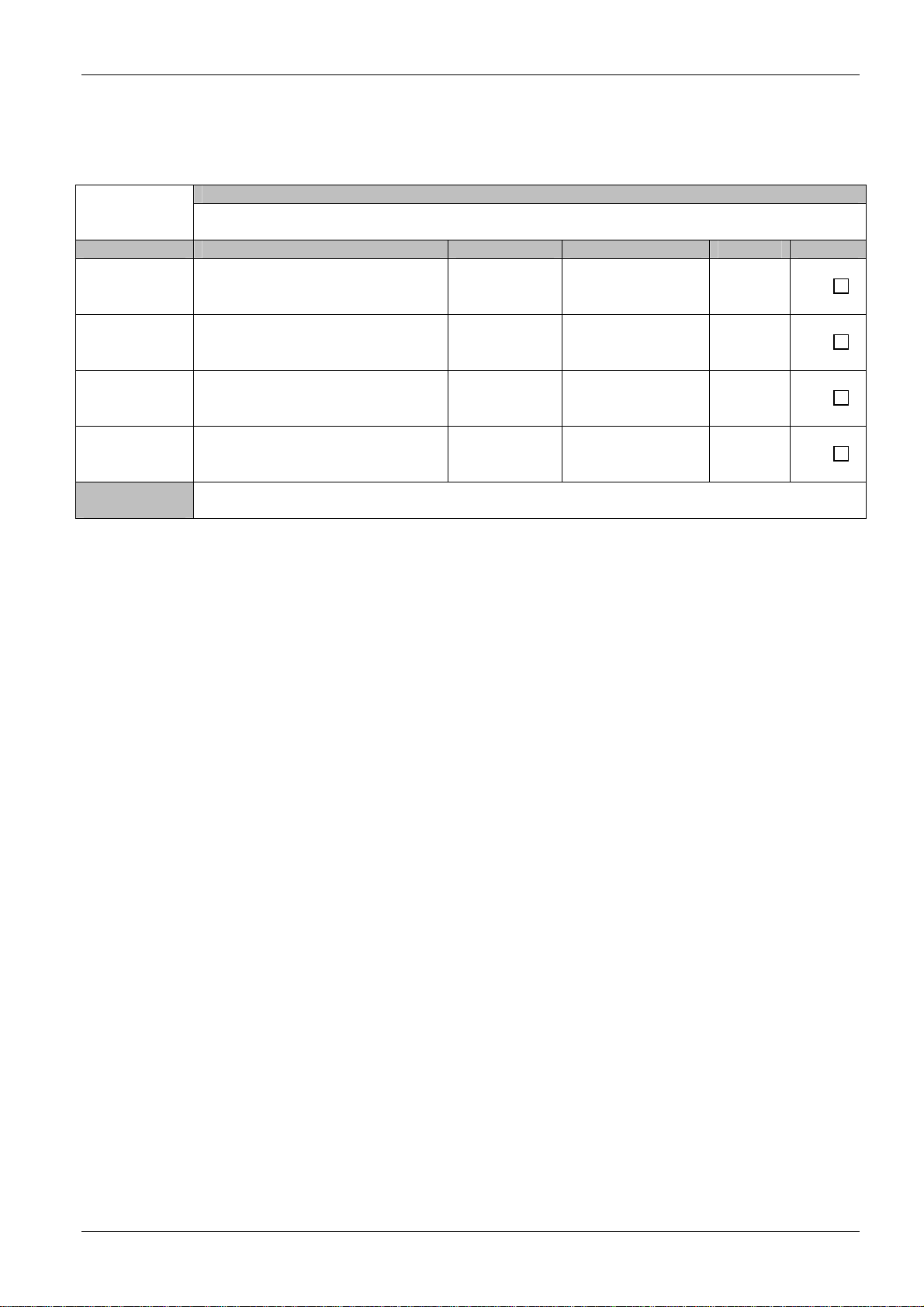
Test procedure:
Connect the RF-Generator to the antenna model Input. Connect the antenna model output to
the Test In port of the RF-Splitter. Switch on the RF-Generator.
f = 127.000 MHz, Level = 0 dBm, Modulation AM: 800 Hz, m=60%.
Check the functionality of all control elements at all DF-Channels.
TC.Nr. TC. Name Description Criteria Passed
[TC 040.10] Switch «On/Off» - Position «ON» OK
[TC 040.11] LED «+5V» Supply +5V Green OK
[TC 040.12] LED «+15V» Supply +15V Green OK
[TC 040.13] LED «-15V» Supply -15V Green OK
[TC 040.14] LED «Pow» Control lamp receiver
supply voltage Green OK
[TC 040.15] LED «Sql» Control lamp for
receiver squelch Yellow OK
[TC 040.16] LED «F+, F-» Control lamp,
frequency offset LED is off OK
[TC 040.17] LED «No Sync» Control lamp for error
in receiver LED is off OK
[TC 040.18] Display «Frequency
(MHz)» Frequency (MHz)
indication Frequency indicated OK
[TC 040.19] Switch «Local/Remote» Switch for
Local/Remote Mode Local and Remote Mode
switched OK
[TC 040.20] Button «Band» Switch for ATC band
and Marine band ATC band and Marine
band switched OK
[TC 040.21] Switch
«Level/Frequency/QDR»
Switch for Input RX
Level and QDR
(Switch is not fixed)
Input RX Level and QDR
Switched OK
[TC 040.22] Button «↑,↓» Buttons for frequency
change in local mode Frequency changed OK
[TC 040.23] Bearing indication on
Display (*) - With a bearing signal is
« * » displayed OK
[TC 040.24] Sync (o.k , Err.) Synchronizations
LEDs of the control
signals
Green OK
[TC 040.25] Audio Check the audio
output at the
loudspeaker
The audio tone of 800 Hz
should be audible OK
Measurement
Equipment: RF-Generator
Antenna Model