RT-1000 Multichannel
RHOTHETA Page 10 of 18 Installation Manual
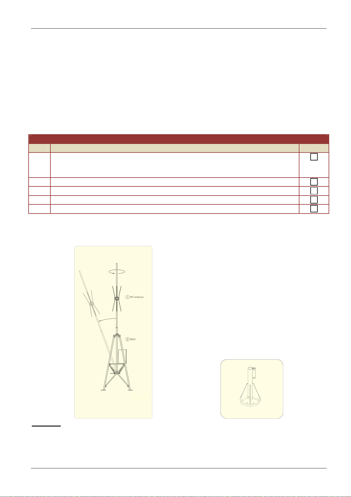
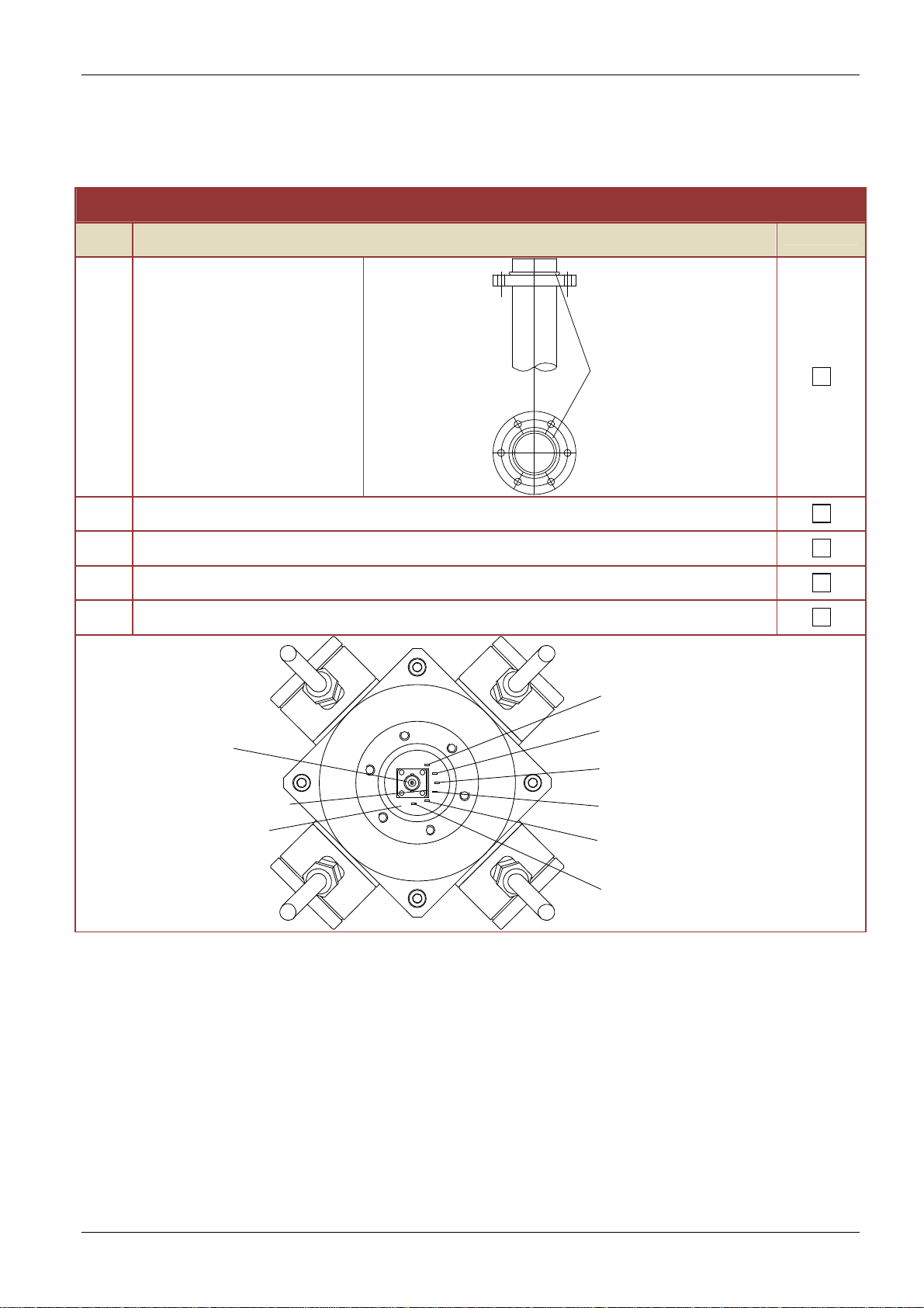
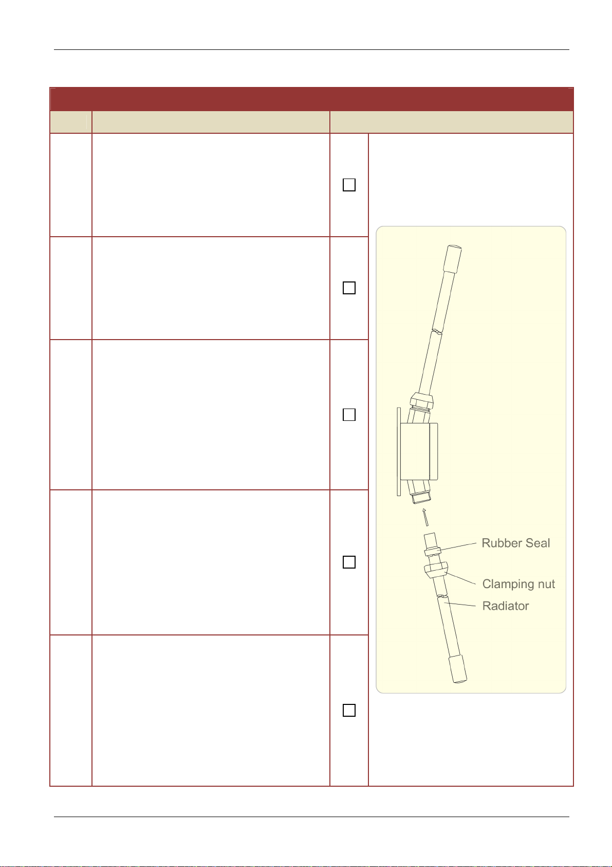
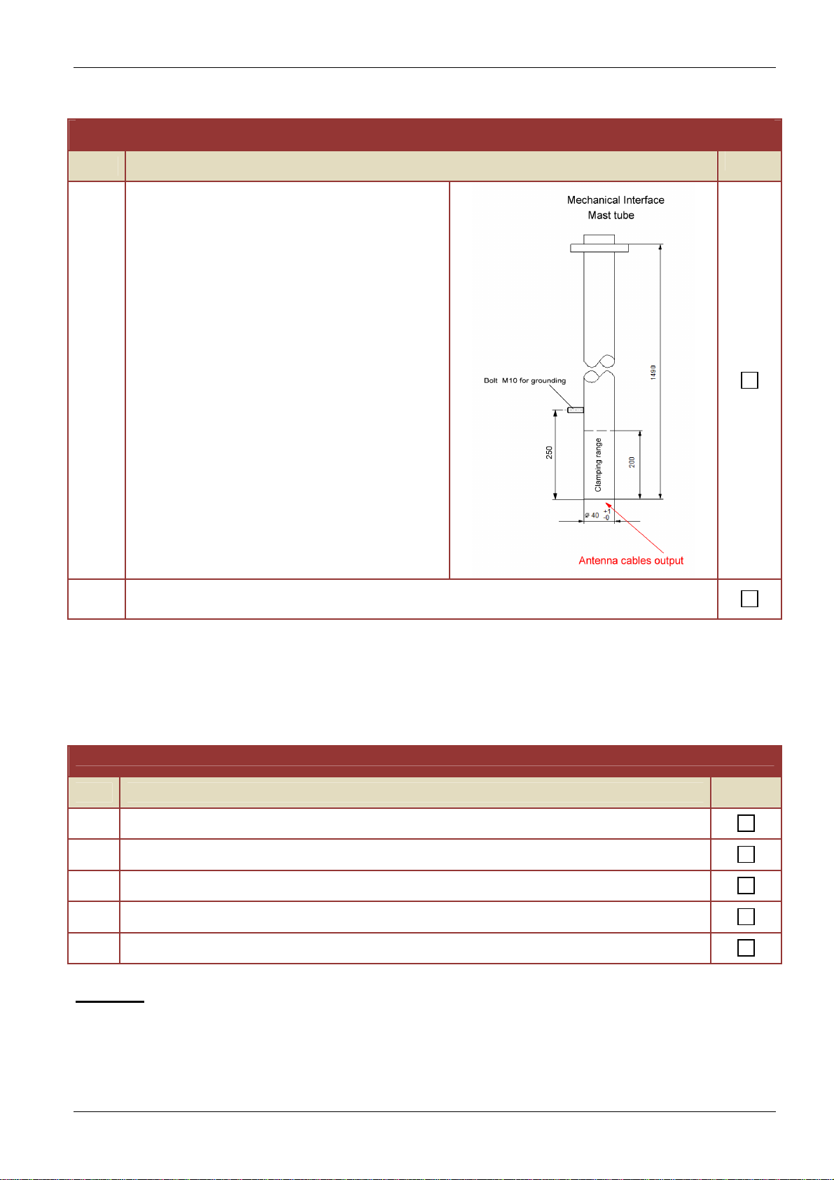
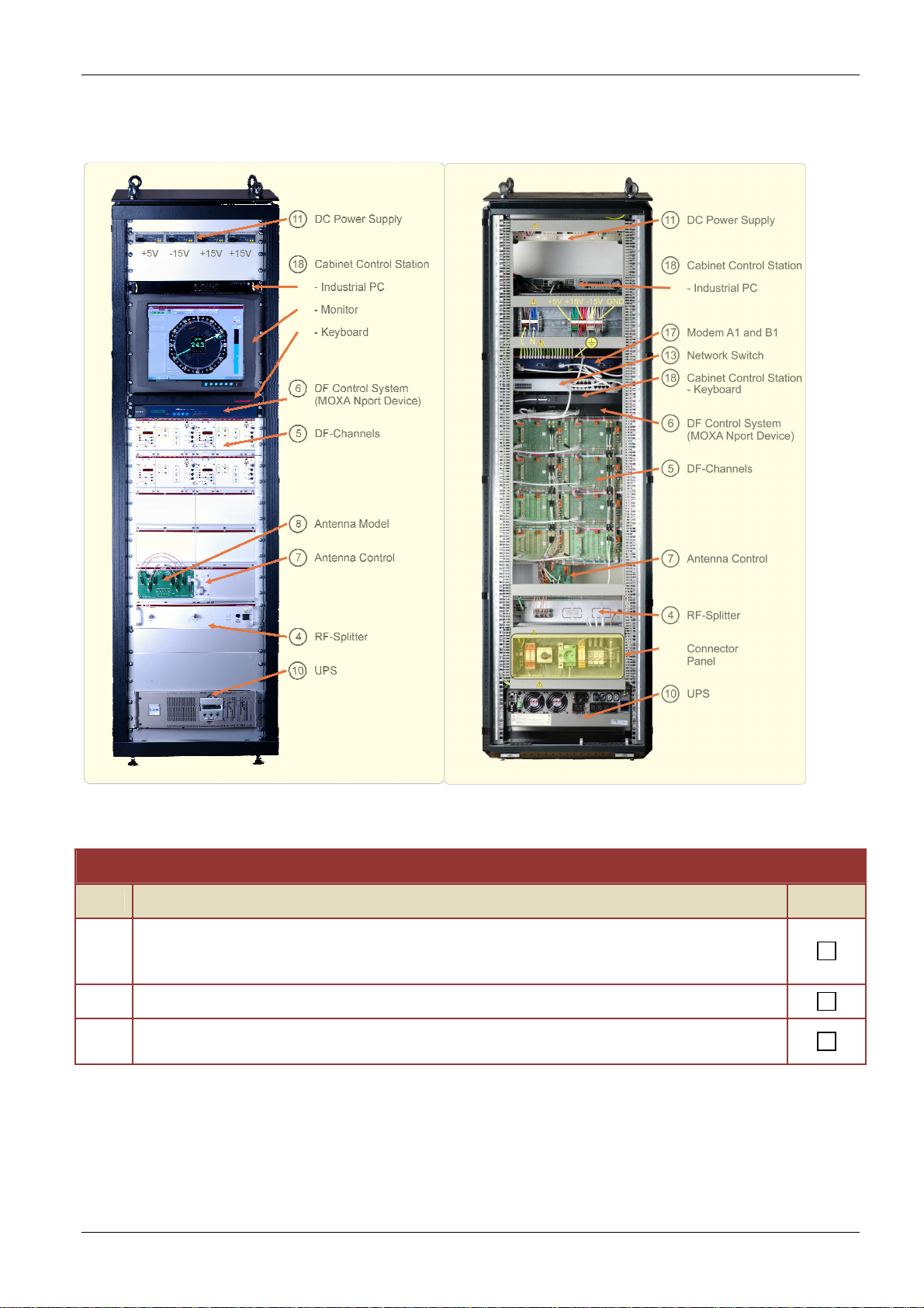
Installation of the DF Main Unit
Step
Description
10 Switch ON the UPS
The UPS displays “Power ON”
11 Switch ON the Main Power Switch
12
Switch ON the DC power supplies. (from left to right)
•+ 5 V
•- 15 V
•+ 15 V one
•+ 15 V two
The Power-ON LEDs must light up (green and orange)
13 Switch on the RF-Splitter
(described in the user manual of the RF-Splitter)
The green Power-ON LED must light up
14
Switch ON the DF Channels successively
If there is a problem in one channel, do not switch on the other channels.
Solve the problem before.
•The 3 Power-ON LEDs must light up green
If a Power-ON LED is Red, control the DC fuses of the DF Channel
If a Power-ON LED do not light up, control the particular Power
supply.
•The Receiver Power LED must light up green.
•Behave the receiver start up sequence described in the DF Channel
user manual. The frequency display started with “88888888”, followed
by the system identification “RT-1000 A” and the actual software
revision.
15 Switch ON the DF Control System, the MOXA NPort device.
The actual IP address should be displayed in the MOXA display.
16 Control the Power On LED of the network switch
17 Control the Power On LED of the DSL Modems
18 Switch on the IPC and the Monitor