Chapter 1
1 .1 Name of Each Part ....................................................................................................... 4
1.2 Specifications ............................................................................................................... 5
1.3 Features ....................................................................................................................... 6
Chapter 2
2.1 Placement of Each Electrical Component .................................................................... 7
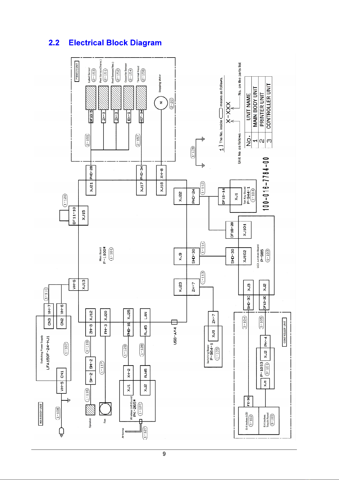
2.2 Electrical Block Diagram ............................................................................................... 9
2.3 Printed Circuit Boards ................................................................................................. 1 O
Chapter 3
2.3.1 Main Board: PWB'P-1100'B (PN 158280) ........................................................... 10
2.3.2 Power Switch Board: PWB'P-984'-1(PN 158263) ...............................................13
2.3.3 LCD Junction Board: PWB'P-985'(PN 87519) .................................................... 13
2.3.4 Numeric Keypad Board: PWB'P-944'-1 (PN 185572)
..........................................
14
2.3.5 Touch Panel Relay Board: PWB'P-1033'(PN 198416)
........................................
14
2.3.6 Wireless LAN Board: PWB'PK-265'B(PN 119158)
.............................................
15
..............................................................................
3.1 Description Items ........................................................................................................ 16
3.2 Removing Controller Unit, Printer Cover, and Body Case .......................................... 17
3.2.1 Removing the Controller Unit ............................................................................. 17
3.2.2 Removing the Printer Cover ............................................................................... 18
3.2.3 Removing the Body Case ................................................................................... 19
3.3 Replacing and Repositioning the Thermal Head ........................................................ 21
3.3.1 Replacing the Thermal Head .............................................................................. 21
3.3.2 Adjusting the Thermal Head Position ................................................................. 22
3.4 Replacing the Label Gap Sensor ................................................................................ 24
3.5 Replacing the Peel Sensors ....................................................................................... 25
3.6 Replacing the Fan ...................................................................................................... 26
3.7 Replacing the Wireless LAN Board ............................................................................ 27
3.8 Replacing the Main Board and Downloading Firmware .............................................. 28
3.8.1 Replacement of Main Board (P-1100) ................................................................. 29
3.8.2 Downloading Firmware for P-1100 Board aer Board Replacement ................... 31
3.9 Replacing the Switch Power Supply Unit .. .................................................................. 36
3.10 Replacing the Cassette Sensor .................................................................................. 37
3.11 Replacing the Electrical Components in the Controller Unit ....................................... 38
3.12 Consumable Pas/ Periodic Replacement Parts ....................................................... 39
3
3.8.3
Replacing the CF (Compact Flash) Card ...............................................................35