2iQUBE Installation Manual
Configuration consists of the following steps:
Define Load Cells: This is the electrical sensitivity
(mV/V output) and capacity specification of the load
cells. Load cell names and serial number can also be
specified.
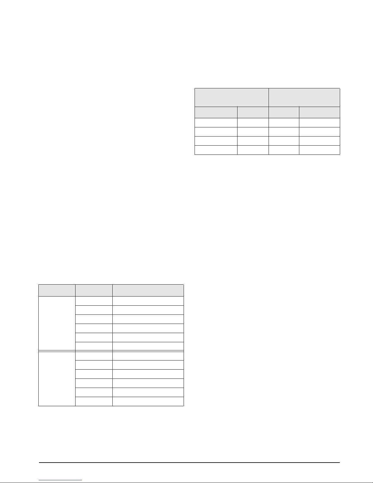
Define Platforms: Any iQUBE board can assign load
cells to two separate platforms. A maximum of four
platforms can be defined in an iQUBE system. The
relationship between load cells is also defined as a
paired or circular arrangement.
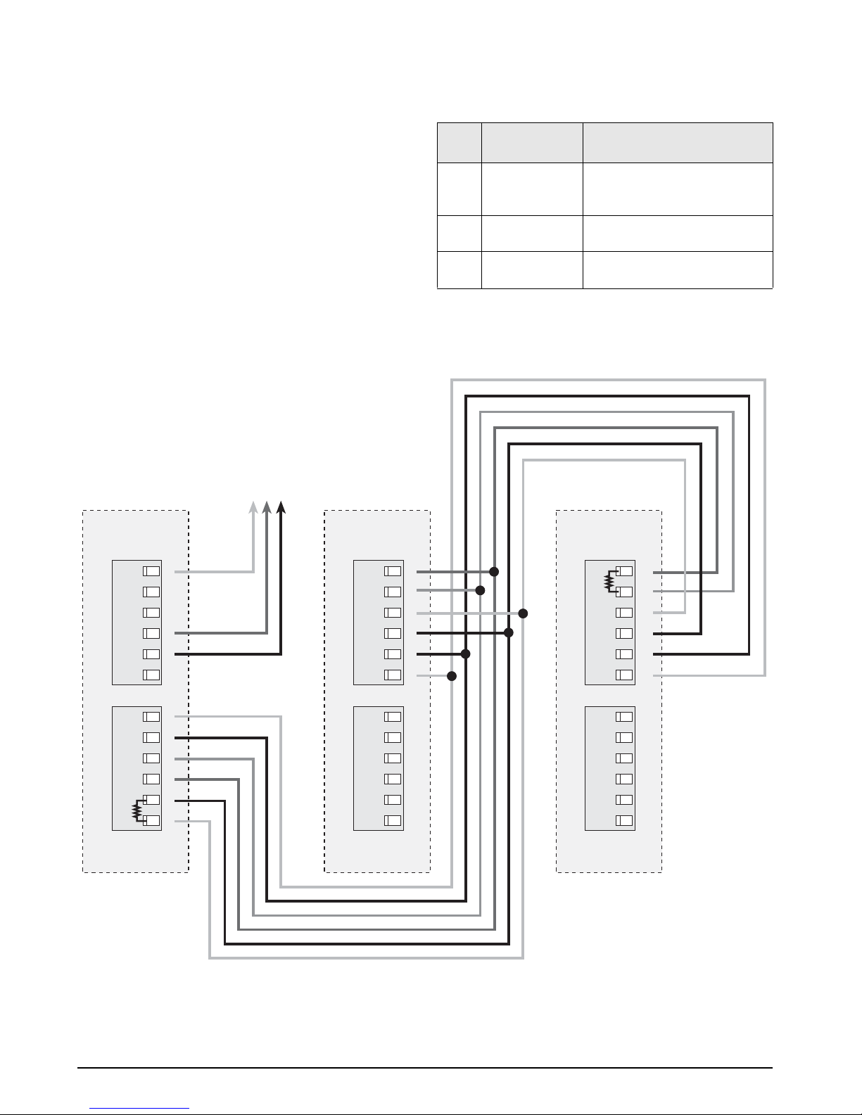
Define Systems: The platforms can be assigned to a
system. Up to four unique systems can be defined,
however the 920i will only support one system per
serial channel.
Load Cell Trimming and Calibration
Cal-Match™calibration calculates the load cell trim
based on a comparison of the signal generated by an
applied weight for each load cell to the signal
generated by all other load cells. If a known test
weight value is used, this calibration also sets the span
for the scale.
Three types of Cal-Match calibration can be
performed using the iQUBE. Each type of calibration
captures the initial dead load of the scale and provides
a means to trim the outputs of the load cells.
Theoretical calibration allows each cell to be zeroed
and trim factors calculated. Based on the cell capacity
and sensitivity, the iQUBE calculates weight values
based on the total signal from all of the cells.
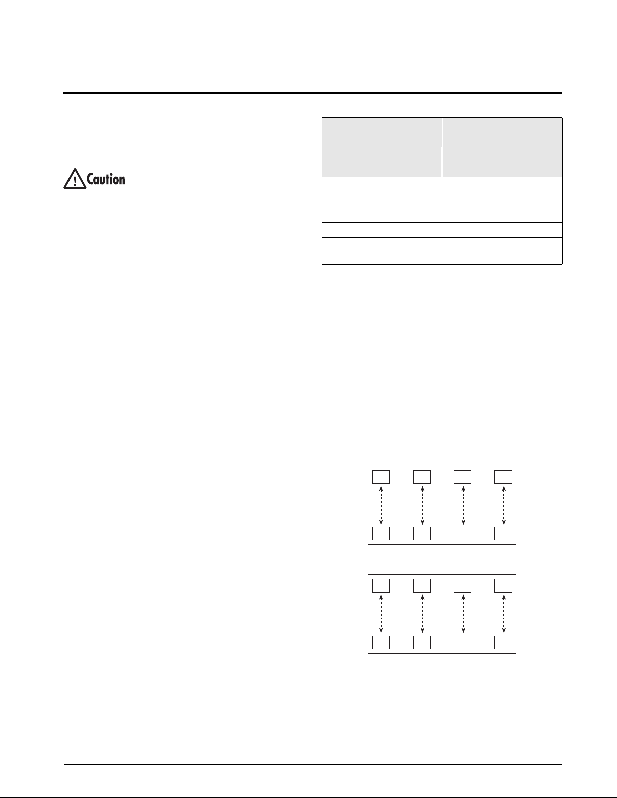
Section calibration requires a weight to be placed
over each section. Trimming can be performed by
running a weight cart down the middle of the
platform, stopping for calibration of each section.
Corner calibration requires weight to be placed over
each cell individually. Corner trimming can be
performed for platforms using an even or odd number
of cells.
Diagnostics
Diagnostic functionality can be enabled for the iQUBE
to identify abnormal load cell outputs. This is based
on the reference established through cell associations.
The diagnostic conditions that can be identified for
paired configurations are open bridge or channel, zero
reference tolerance, drifting, peak-to-peak noise, and
out-of-balance conditions. Diagnostic conditions
recognized for circular configurations are limited to
open bridge or channel, drifting, and peak-to-peak
noise.
Error conditions generate a displayed error message if
connected to the 920i which, with an Ethernet card,
can be configured to e-mail the alert message to an
address. In addition, there is a visual LED indication
on the connector board to identify any load cell that
appears to have an abnormal condition.
Cell Emulation
Cell emulation allows the output of a failed load cell
to be emulated. Automatic or manual cell emulation
can be specified (limited to one cell per scale system),
using either truck scale (Type 1) or tank/hopper/floor
scale (Type 2) emulation algorithms.
NOTE: Satisfactory results from cell emulation require the
load to be centered and the scale installation to be plumb and
level.
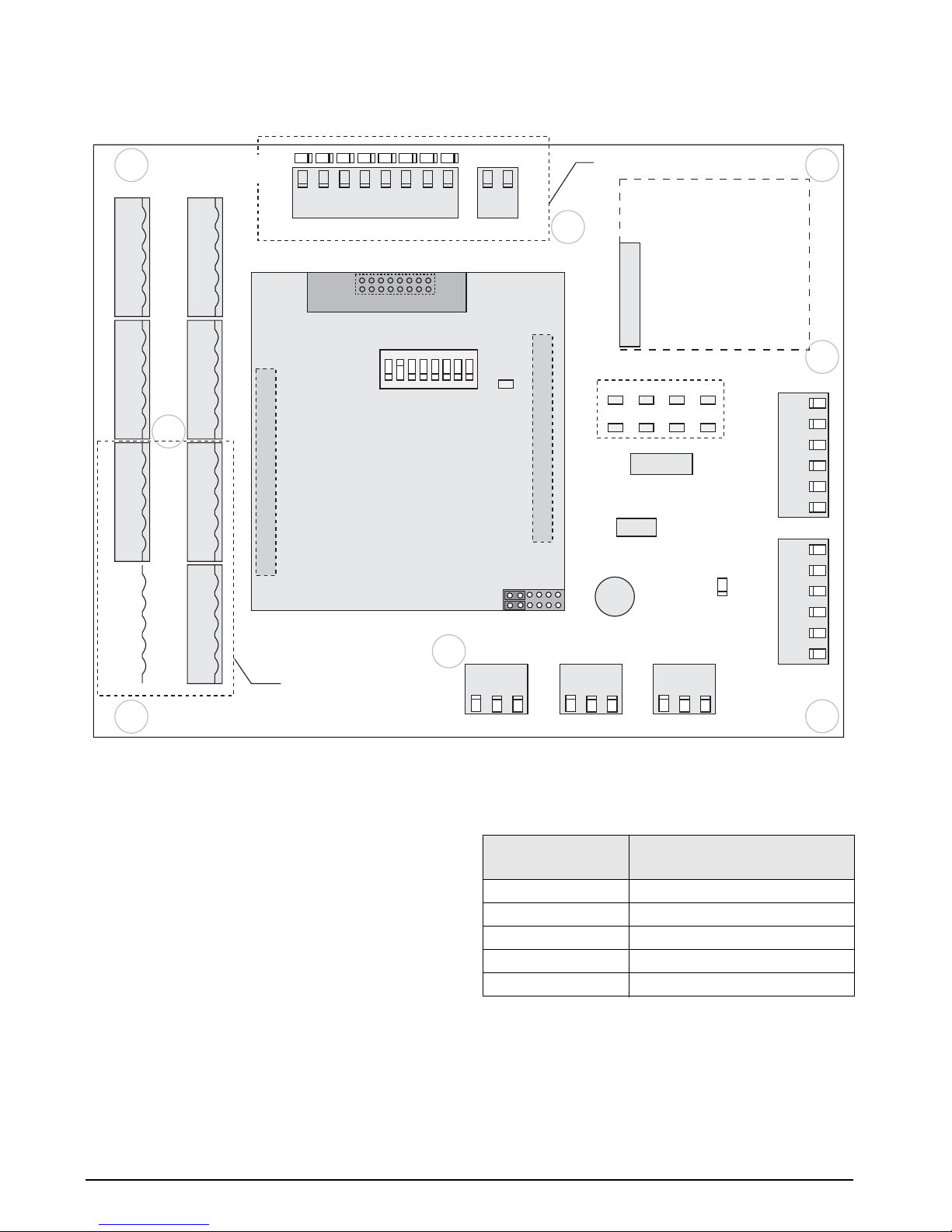
1.1 System Configurations and Options
Table 1-1 lists iQUBE model and option part numbers.
920i part numbers listed are for models without A/D
cards.
Model / Option PN
4-channel iQUBE 77778
8-channel iQUBE 77148
8-channel iQUBE with digital I/O 77728
iQUBE internal power supply, 6 VDC 77531
iQUBE internal Ethernet interface 77142
iQUBE internal fiber-optic interface 77143
920i internal fiber-optic interface 77788
920i internal Ethernet communications card 71986
920i Serial expansion card 67604
Remote (external) fiber-optic interface 77789
Analog output, 0–30 mV 77146
Analog output, 4–20 mA 77797
920i universal model, 115 VAC 77790
920i universal model, 230 VAC 77791
920i panel mount model, 115 VAC 77792
920i panel mount model, 230 VAC 77793
920i wall mount model, 115 VAC 77794
920i wall mount model, 230 VAC 77795
Table 1-1. iQUBE Model and Option Part Numbers