RP-II-CS8G [C]
18
Sheet 3 of 16
www.richards-mfg.com
Product Family
CS8
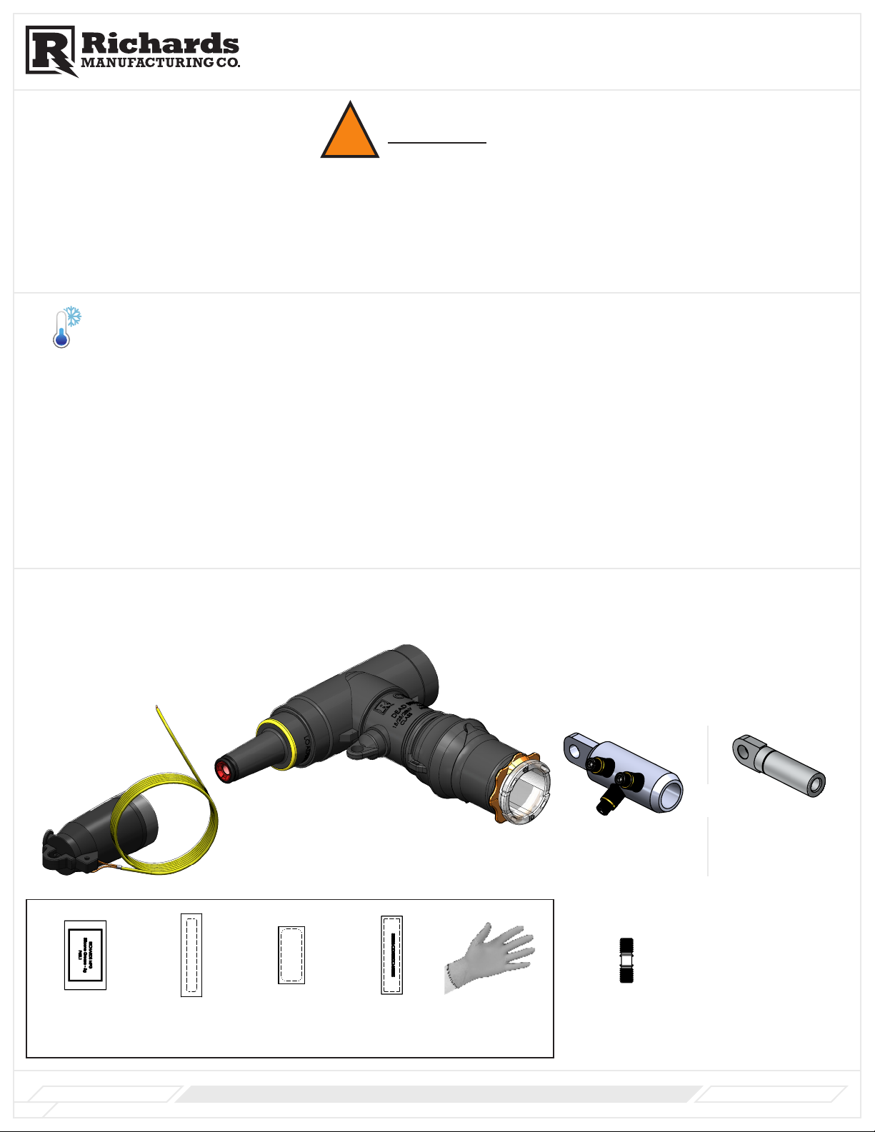
TIP: Use To-Scale Cable Cutback Template as aid to prepare cable.
NOTE: Certain items used, such as PVC tape, may not be included.
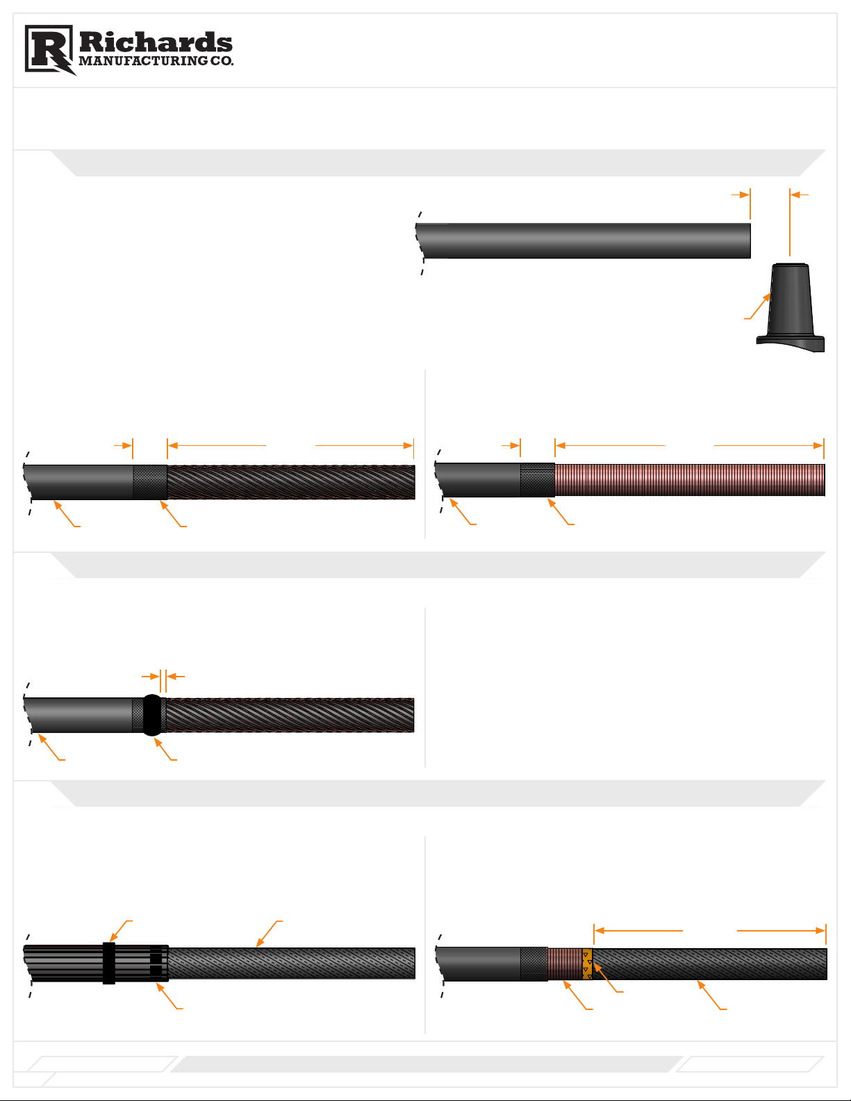
1Positioning Cable & Exposing Metallic Shield
A. Straighten and train cable end. Cable should be free to move
approximately 2" in either direction.
B. Cut cable to dimensions shown.
C. Clean cable jacket approximately 24" from end of cable.
TIP:
Use to-scale cable cutback template on last page as aid to prepare cable.
NOTE:
Certain items used such as mastic, PVC tape, shrink tube, etc. may not be included.
Product Family
LCN/LCT
Installation Instructions
www.richards-mfg.com
RP-II-62LCN [E]
Rev. E
Sheet 9 of 9
517 Lyons Ave.
Irvington, NJ 07111
Phone (973) 371-1771
Fax (973) 371-4304
www.richards-mfg.com
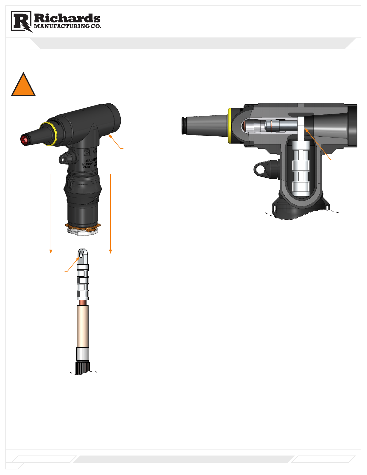
1 3/4”
Bushing or
Mating Part
For Strap/Wire Shielded Cable
D. Remove cable jacket to dimensions shown.
E. Abrade area as shown.
For Metallic Tape/LC Shielded Cable
D. Remove cable jacket to dimensions shown.
E. Abrade area as shown.
For Strap/Wire Shielded Cables
For Strap/Wire Shielded Cables
STEP 0-Positioning
the Cable
STEP 1-Exposing
Cable Shielding
For Metallic Tape Shielded/LC Shielded
For Metallic Tape Shielded/LC Shielded
For Metallic Tape Shielded/LC Shielded
STEP 3- Exposing Cable
Semi-Conductive Shield
For Strap/Wire Shielded Cables
TIP:
NOTE:
Jacket Mastic
STEP 2-Applying Jacket
Mastic
Jacket Mastic
Product Family
CSHN/CSHT
Installation Instructions
Cable Jacket Abraded Area
1 1/2” REF. 11”
For Strap/Wire Shielded Cables
For Strap/Wire Shielded Cables
STEP 0-Positioning
the Cable
STEP 1-Exposing
Cable Shielding
For Metallic Tape Shielded/LC Shielded
For Metallic Tape Shielded/LC Shielded
For Metallic Tape Shielded/LC Shielded
STEP 3- Exposing Cable
Semi-Conductive Shield
For Strap/Wire Shielded Cables
TIP:
NOTE:
Jacket Mastic
STEP 2-Applying Jacket
Mastic
Jacket Mastic
Product Family
CSHN/CSHT
Installation Instructions
1 1/2” REF. 12”
Cable Jacket Abraded Area
A. Straighten and train cable end. Cable should be free to move
approximately 2" in either direction.
B. Cut cable to dimensions shown.
C. Clean cable jacket approximately 24" from end of cable.
TIP:
Use to-scale cable cutback template on last page as aid to prepare cable.
NOTE:
Certain items used such as mastic, PVC tape, shrink tube, etc. may not be included.
Product Family
LCN/LCT
Installation Instructions
www.richards-mfg.com
RP-II-62LCN [E]
Rev. E
Sheet 9 of 9
517 Lyons Ave.
Irvington, NJ 07111
Phone (973) 371-1771
Fax (973) 371-4304
www.richards-mfg.com
1 3/4”
Bushing or
Mating Part
For Strap/Wire Shielded Cable
D. Remove cable jacket to dimensions shown.
E. Abrade area as shown.
For Metallic Tape/LC Shielded Cable
D. Remove cable jacket to dimensions shown.
E. Abrade area as shown.
For Strap/Wire Shielded Cables
For Strap/Wire Shielded Cables
STEP 0-Positioning
the Cable
STEP 1-Exposing
Cable Shielding
For Metallic Tape Shielded/LC Shielded
For Metallic Tape Shielded/LC Shielded
For Metallic Tape Shielded/LC Shielded
STEP 3- Exposing Cable
Semi-Conductive Shield
For Strap/Wire Shielded Cables
TIP:
NOTE:
Jacket Mastic
STEP 2-Applying Jacket
Mastic
Jacket Mastic
Product Family
CSHN/CSHT
Installation Instructions
Cable Jacket Abraded Area
1 1/2” REF. 11”
For Strap/Wire Shielded Cables
For Strap/Wire Shielded Cables
STEP 0-Positioning
the Cable
STEP 1-Exposing
Cable Shielding
For Metallic Tape Shielded/LC Shielded
For Metallic Tape Shielded/LC Shielded
For Metallic Tape Shielded/LC Shielded
STEP 3- Exposing Cable
Semi-Conductive Shield
For Strap/Wire Shielded Cables
TIP:
NOTE:
Jacket Mastic
STEP 2-Applying Jacket
Mastic
Jacket Mastic
Product Family
CSHN/CSHT
Installation Instructions
1 1/2” REF. 12”
Cable Jacket Abraded Area
11” 11 3/4”
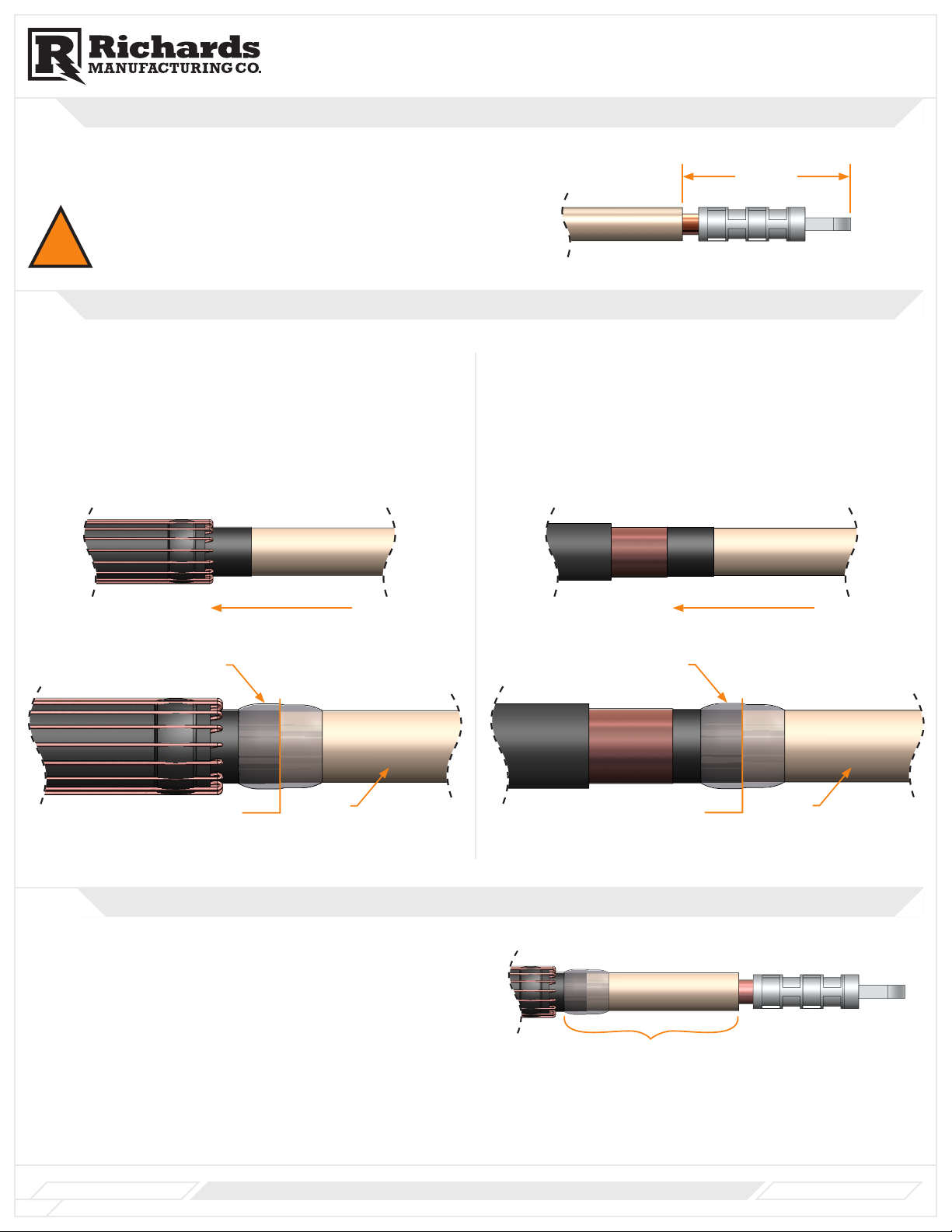
2Applying Jacket Mastic
For Strap/Wire Shielded Cable
A. Apply one piece of jacket mastic at position shown by stretching and
wrapping with light tension fully around outer jacket.
For Metallic Tape/LC Shielded Cable
Go to Step 3
NOTE: Jacket mastic will be applied in Step 10.2
For Strap/Wire Shielded Cables
For Strap/Wire Shielded Cables
STEP 0-Positioning
the Cable
STEP 1-Exposing
Cable Shielding
For Metallic Tape Shielded/LC Shielded
For Metallic Tape Shielded/LC Shielded
For Metallic Tape Shielded/LC Shielded
STEP 3- Exposing Cable
Semi-Conductive Shield
For Strap/Wire Shielded Cables
TIP:
NOTE:
Jacket Mastic
STEP 2-Applying Jacket
Mastic
Jacket Mastic
Product Family
CSHN/CSHT
Installation Instructions
Cable Jacket Jacket Mastic
1/4”
3Exposing Cable Semi-Conductive Shield
For Strap/Wire Shielded Cable
A. Fold back strap/wire shields and press firmly into jacket mastic.
B. Secure strap/wire shields 3” back from jacket mastic with binding wire
or zip tie as shown.
For Metallic Tape/LC Shielded Cable
A. Wrap 2 layers of PVC tape at dimension shown to secure metallic shield.
B. Remove metallic shield up to PVC tape as shown.
For Strap/Wire Shielded Cables
For Strap/Wire Shielded Cables
STEP 0-Positioning
the Cable
STEP 1-Exposing
Cable Shielding
For Metallic Tape Shielded/LC Shielded
For Metallic Tape Shielded/LC Shielded
For Metallic Tape Shielded/LC Shielded
STEP 3- Exposing Cable
Semi-Conductive Shield
For Strap/Wire Shielded Cables
TIP:
NOTE:
Jacket Mastic
STEP 2-Applying Jacket
Mastic
Jacket Mastic
Product Family
CSHN/CSHT
Installation Instructions
Binding Wire or Zip Tie Semi-Conductive Shield
Jacket mastic under strap/wire shield
For Strap/Wire Shielded Cables
For Strap/Wire Shielded Cables
STEP 0-Positioning
the Cable
STEP 1-Exposing
Cable Shielding
For Metallic Tape Shielded/LC Shielded
For Metallic Tape Shielded/LC Shielded
For Metallic Tape Shielded/LC Shielded
STEP 3- Exposing Cable
Semi-Conductive Shield
For Strap/Wire Shielded Cables
TIP:
NOTE:
Jacket Mastic
STEP 2-Applying Jacket
Mastic
Jacket Mastic
Product Family
CSHN/CSHT
Installation Instructions
10”
PVC Tape
Semi-Conductive
Shield
Metallic Shield
10”