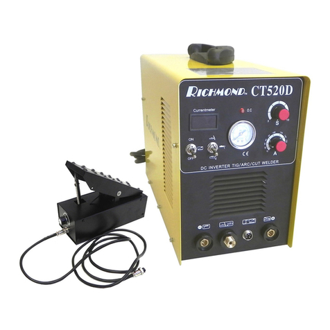
Richmond CUT-40F User manual

RICHMOND
CUT-40F, CUT-50F, CUT-60F, CUT-80, CUT-100
PILOT ARC INVERTER PLASMA CUTTER
INSTRUCTION MANUAL

Thank you for using our cutting machine!
For your safety, please rea this manual book before operation.
2
GURANTEE
We give our unreserve guarantee that the Inverter Wel ing an
Cutting machines comply with IEC974 international safety
stan ar . Maintenance for one year since the ate of purchase.
Service of this equipment is restricte to traine personnel;
unqualifie personnel are strictly cautione against attempting
repairs or a justments not covere in this manual, at the risk of
personal injury an /or voi ing the Warranty.

Following a en ions should be observed for safe y guaran ee
a. Confirm the followings such as supply power connected from your side, the spot for welder’s
installing, high-pressure gas, storage of workpiece and the treatment of rubbish according to
your national laws or your company’s standards.
b. On spot of welding
To avid from the injure and hurt by smoke and bad gas, the e haust equipments ought to be
installed or useful breath apparatus should be used, depending on your rules.
c. Don’t open up the welder or use it in open position.
Avoid any possible danger
a. Avoid burning from over-heat
Keep the welder from the wall more than 30cm and from combustible articles more than 50cm.
b. Avoid burning from spark
Keep spark far away from tinder or open holes.
c. Avoid welder from impact or falling
Fasten the welder by fi ed bolts.
d. Don’t weld the tubes with gas or hermetic tubes and vessels.
e. Don’t hang the torch on the gas bottle or touch the bottle with electrode.
f. For your health, please wear the protecting articles according to your relevant rules.
A en ion while connec ing
a. Only after disconnection of power and safety ensuring, the connection of welder can be
operated.
b. Don’t touch the parts with electricity or wear the wet broken gloves.
c. The cables should be selected according to the appointed standard.
d. Don’t place the heavy on cables.
e. The cables should be well connected and the bare electric parts should be wrapped with
insulation.
f. Only electrician with certificate can do grounding of welder or workpiece.
g. The power of all equipments should be turned off while not using.
h. The welding cables should be shortened as possible.
3
SAFETY ATTENTION

i. Place the cables nearly to the floor or ground with e tending position.
j. Place the cables of workpiece and cables of torch in parallel.
k. The grounding of workpiece can’t be used together with other machines.
4

A. Plasma
Plasma cutters work by sen ing a pressurize gas, such as air, through a small channel. In the center of this
channel, you'll fin a negatively charge electro e. The electro e is at the center, an the nozzle is just below it.
The swirl ring causes the plasma to turn rapi ly as it passes. When you apply power to the negative electro e,
an you touch the tip of the nozzle to the metal, the connection creates a circuit. A powerful spark is generate
between the electro e an the metal. As the inert gas passes through the channel, the spark heats the gas until it
reaches the fourth state of matter. This reaction creates a stream of irecte plasma, approximately 30,000 F
(16,649 ) or more an moving at 20,000 feet per secon (6,096 m/sec) that re uces metal to vapor an molten℃
slag.
The plasma itself con ucts electrical current. The cycle of creating the arc is continuous as long as power is
supplie to the electro e an the plasma stays in contact with the metal that is being cut. The cutter nozzle has a
secon set of channels. These channels release a constant flow of shiel ing gas aroun the cutting area. The
pressure of this gas flow effectively controls the ra ius of the plasma beam.
NOTE! This machine is esigne to use only compresse air as the “gas”.
B. Voltage Regulation
The Automatic Voltage Compensation circuit prevents voltage loa from excee ing maximum in accor ance
with the main technical ata sheet an shortening the life of the machine.
C. Thermal Protection
The thermal protection circuits will engage if unit excee s uty cycle. This will cause the machine to stop
working. The in icator will be lit on the front of the machine. The fan will most likely continue to run until unit
cools own. When it reaches an acceptable temperature, it will operate again.
E. Duty Cycle
Duty cycle is the percentage of on time (measure in minutes) in a 10-minute perio in which the machine can
be operate continually, in an environment of a specifie temperature.
Excee ing uty cycle ratings will cause the thermal overloa protection circuit to become energize an shut
own output until the unit cools to normal operating temperature. Continual excee ing of uty cycle ratings can
cause amage to the machine.
5
DE FINITI NS

Model CUT-40F CUT-50F CUT-60F CUT-80 CUT-100
Power supply voltage 1-ph AC 220±10% V 3-phs AC 220±10% V
Power frequency 50~60 Hz 50~60 Hz 50~60 Hz 50~60 Hz 50~60 Hz
Power supply capacity 4.7 kVA 6.0 kVA 7.5 kVA 10.5 kVA 15 kVA
Rated input current 20 A 25 A 30 A 30 A 30 A
No-load voltage 230 V 230 V 240 V 240 V 240 V
Output current range 10-40 A 10-50 A 10-60 A 20-80 A 20-100 A
Output voltage 96 V 102 V 108 V 108 V 108 V
Duty cycle 60% 60% 60% 60% 60%
Efficiency 85% 85% 85% 85% 85%
Tip hole diameter 1.0 mm 1.0 mm 1.2 mm 2.0 mm 2.0 mm
Arc striking model Untouch Untouch Untouch Untouch Untouch
Cosφ (η) 0.93 0.93 0.93 0.93 0.93
Air pressure 0.4 MPa 0.4 MPa 0.5 MPa 0.6 MPa 0.6 MPa
Cutting
thickness
Steel 1-8 mm 1-10 mm 1-13 mm 1-20 mm 1-25 mm
Aluminum 1-6 mm 1-8 mm 1-10 mm 1-12 mm 1-16 mm
Copper 1-4 mm 1-6 mm 1-8 mm 1-10 mm 1-12 mm
Air flow 100 L/min 110 L/min 120 L/min 140 L/min 140 L/min
Insulation grade F F F F F
Protection grade IP 21S IP 21 S IP 21 S IP 21 S IP 21 S
Net Weight 8.9 kg 9.2 kg 14.7 kg 23.8 kg 23.8
Dimensions (mm) 385*155*295 385*155*295 500*210*365 520*330*375 520*330*375
6
MA IN T ECH NICAL D ATA
Spec.

A. Unpacking
Unpack all items an verify that all items have been receive accor ing to the packing list enclose .
B. perating Environment
Make sure working area is well ventilate . The unit is coole by an axial-flow fan which provi es airflow
through the back panel over the electronics an out the machine cover vents. (NOTE! The cover must be
installe with the vents closest to the front of the machine) Provi e at least 15cm at the rear an 15cm on each
si e for clearance. If unit is operate without sufficient cooling air, the uty cycle will be greatly re uce .
C. Input Cable Connection
Every machine inclu es a primary input power cable capable of han ling the input voltage an current for this
unit. If the unit is connecte to power that excee s the require voltage, or is of the incorrect phase, serious
amage will be incurre an warranty will become voi .
CUT40F, CUT50F an CUT60F machine must be operate on 220 volts single phase 50/60Hz; CUT80 an
CUT100 machine must be operate on 220 volts three phases 50/60Hz.
Neutral (Groun ) wire is yellow with a green stripe or soli green. This wire must be connecte to the “groun ”
terminal of the power plug you use.
D. Torch Connection
Connect the Torch to the inverter by screwing the air line fitting on the en of the torch to the torch connector
fitting on the front of the machine.
Secure by tightening with wrench slightly. DO NOT OVER TIGHTEN!
7
INSTALLATI N

Position the torch with the shield cup facing upward and unscrew and remove the ceramic shield cup
from the torch head assembly (The ceramic shield cup holds the tip and electrode in place).
Remove the tip, ceramic swirl ring, and electrode.
Install the electrode and tip. Replace worn parts, as necessary.
Install and tighten the ceramic shield cup until it is seated on the torch head. If resistance is felt when
installing the cup, check the threads and parts configuration before proceeding.
Note: On some torches that do not have reversible electrodes it will be necessary to secure the electrode by
slightly tightening with pliers to assure reliable electrical connection.
8
T RCH ASSEM BLY

To Begin
Turn the Power Switch to the ON position.
Position yourself to where you can rea the air pressure. Press the torch switch (air will exhaust from torch,
a just the air regulator to rea approximately 0.4 to 0.6 MPa an release torch switch.
Secure groun clamp to workpiece. Connect clamp to main part of workpiece, not the part being remove .
Cutting
Position torch tip slightly above workpiece, press torch switch an lower torch tip towar workpiece about 3-
5mm istance, an cutting arc will strike. As there’s a steel ring to keep the istance from tip to workpiece, so
you can just touch the steel ring to workpiece. You’ better cut from the fringe of wokpiece, if you want to cut
in the mi le of workpiece, you’ better keep a slightly angle to ensure blow the melte metal. After cutting arc
is establishe , move the torch in the esire irection.
This metho ology is calle Drag-Cutting. Avoi moving too fast as woul be in icate by sparks ra iating
from the top si e of workpiece. Move the torch just fast enough to maintain sparks concentration at the
un ersi e of the work-piece an making sure the material is completely cut through before moving on. A just
rag spee as esire /require .
Stand-off Cutting
In some cases, it may be beneficial to cut with the torch tip raise above the work-piece approximately 1/16" to
1/8” to re uce material blow-back into the tip an to maximize penetration of thick material cuts. An example
of "stan -off cutting" woul be use when penetration cutting or gouging operation is being performe . You
can also use “stan -off” technique when cutting sheet metal to re uce the chance of splatter-back tip amage.
Piercing
For piercing, position the tip approximately 3.2 mm above the workpiece. Angle the torch slightly to irect
sparks away from the torch tip an operator.
Initiate the pilot arc an lower the tip of the torch until the main cutting arc transfers, sparks start.
Start the pierce off the cutting line on the scrap piece or template an then continue the cut onto the cutting line.
Hol the torch perpen icular to the workpiece after the pierce is complete an continue cutting as esire .
Clean spatter an scale from the shiel cup an the tip as soon as possible.
Quality Cuts
Dross (slag) is the excess material that spatters an buil s up on the un ersi e of the work-piece as you cut.
Dross occurs when the operating proce ure an technique is less than optimal. It will require practice an
experience to obtain cuts without ross. Although less than optimal cuts will contain ross, it is relatively easy
to remove by breaking it off using pliers or chipping off with a chisel or scraping or grin ing the finishe cut as
9
PERATI N

nee e an is generally only a minor inconvenience.
A combination of factors contributes to the buil up of ross. They inclu e material type, material thickness,
amperage use for the cut, spee of the torch across the work-piece, con ition of the torch tip, input line
voltage, air pressure, etc. Generally there is an inversely proportional relationship between output current an
spee of cut. Do not use more output current than is necessary an a just spee of cut towar minimizing ross
buil up on un ersi e of cut. Experiment with a justing current an spee to minimize ross.
For more specific issues regar ing quality of cuts an general operation, go to the Troubleshooting section of
this manual.
10

Each Use
Each time you use the plasma cutter; check the torch, Tip/Nozzle, Electro e, an Ceramic Shiel cup.
Inspect torch for any wearing, cracks or expose wires. Replace or repair before use.
A worn torch Tip/Nozzle contributes to re uce spee , voltage rop an crooke cuts.
A worn Tip/Nozzle is in icate by an elongate or oversize orifice.
The face of the electro e shoul not be recesse more than 3.2mm. Replace if worn beyon this point.
Weekly
Check for proper fan operation.
Blow or vacuum ust an irt out of the entire machine an the air filter.
11
MAIN ENANCE

Front View of CUT-80
Connect to the cut torch
Back View
12
FR NT & BACK PAN EL VI EW
AIR
PRESSURE
H SE
GAS INLET
AIR
REGULAT
R
P WER
SUPPLY
CABLE

PR BLEM CAUSE S LUTI N
Torch will not come
on
Power switch off Turn power switch to the opposition
Air supply is compromise Another in ication of this is a more green
flame check air supply
Workpiece Groun Clamp not
attache
Attach to workpiece or to steel table with
work piece securely clampe to table
Sparks are shooting
upwar instea of
own through the
material.
Plasma Torch is not piercing
the material
Increase current
Torch may too far away from
stock
Decrease the istance of your torch to stock
Material may not be groun e
properly
Check connections for proper groun .
Travel spee too fast Re uce spee
Beginning of cut not
completely pierce
Possible connection problem Check all connections
Dross buil -up on
parts of cuts
Tool/Material buil ing up heat Allow material to cool then continue cut
Cutting spee too slow or
Current to high
Increase spee an /or re uce current until
ross is re uce to minimum
Worn torch parts Inspect an repair or replace worn parts
Arc stops while
cutting
Cutting spee too slow Increase spee until problem solve
Torch is too high, away from
material
Lower torch to recommen e height
Worn torch parts Inspect an repair or replace worn parts
Workpiece groun cable
isconnecte
Connect Workpiece Groun Clamp to
workpiece or steel table
Insufficient
penetration
Cutting spee too fast Slow travel spee
Torch tilte too much A just tilt
Metal too thick Several passes may be necessary
Worn torch parts Inspect an repair or replace worn parts
Consumables wear
quickly
Excee ing unit capability Material too thick, increase angle to prevent
blow back into torch tip.
Excessive Pilot arc time Do not pilot for more than 5 secon s. You
can also start with torch in contact with
metal.
Improperly assemble torch See section title “Torch Assembly”
Ina equate air supply, pressure
too low.
Check air filter, increase air pressure.
Faulty air compressor Check air compressor operation an make
sure enough input air pressure
13
T URBL E S H TING
This manual suits for next models
4
Table of contents
Other Richmond Welding System manuals
Popular Welding System manuals by other brands

Thermal Dynamics
Thermal Dynamics PakMaster 75XL Plus operating manual

Fimer
Fimer TT165 AC/DC instruction manual

Lincoln Electric
Lincoln Electric HANDY MIG IM756-A Operator's manual

Miller
Miller Subarc AC/DC 1000 owner's manual

Pro Spot
Pro Spot i4 instruction manual

Craftsman
Craftsman 113.201392 owner's manual