Richter SCK Series User manual

INSTALLATION AND OPERATING MANUAL
Translation of the original manual
Keep for future use!
This operating manual must be strictly observed before
transport, installation, operation and maintenance
Subject to change without notice.
Reproduction is generally permitted with indication of the source.
© Richter Chemie-Technik GmbH.
9220-013-en Revision 11 Edition 03/2019
Series SCK
Mechanical Seal
double, to DIN EN 12756

Series SCK, double mechanical seal to DIN EN 12756 Page 2
9220-013-en Revision 11
TM 7827 Edition 03/2019
List of Contents
List of Contents.........................................2
Relevant documents .................................2
1Technical data ......................................2
2Safety, transport, storage and disposal
.....................................................3
2.1 Intended use ................................................ 3
3Product description .............................3
4Commissioning / Shutdown ................3
4.1 Initial commissioning ...................................3
4.2 Mechanical seals .........................................3
4.2.1 Use in an explosive area................................. 3
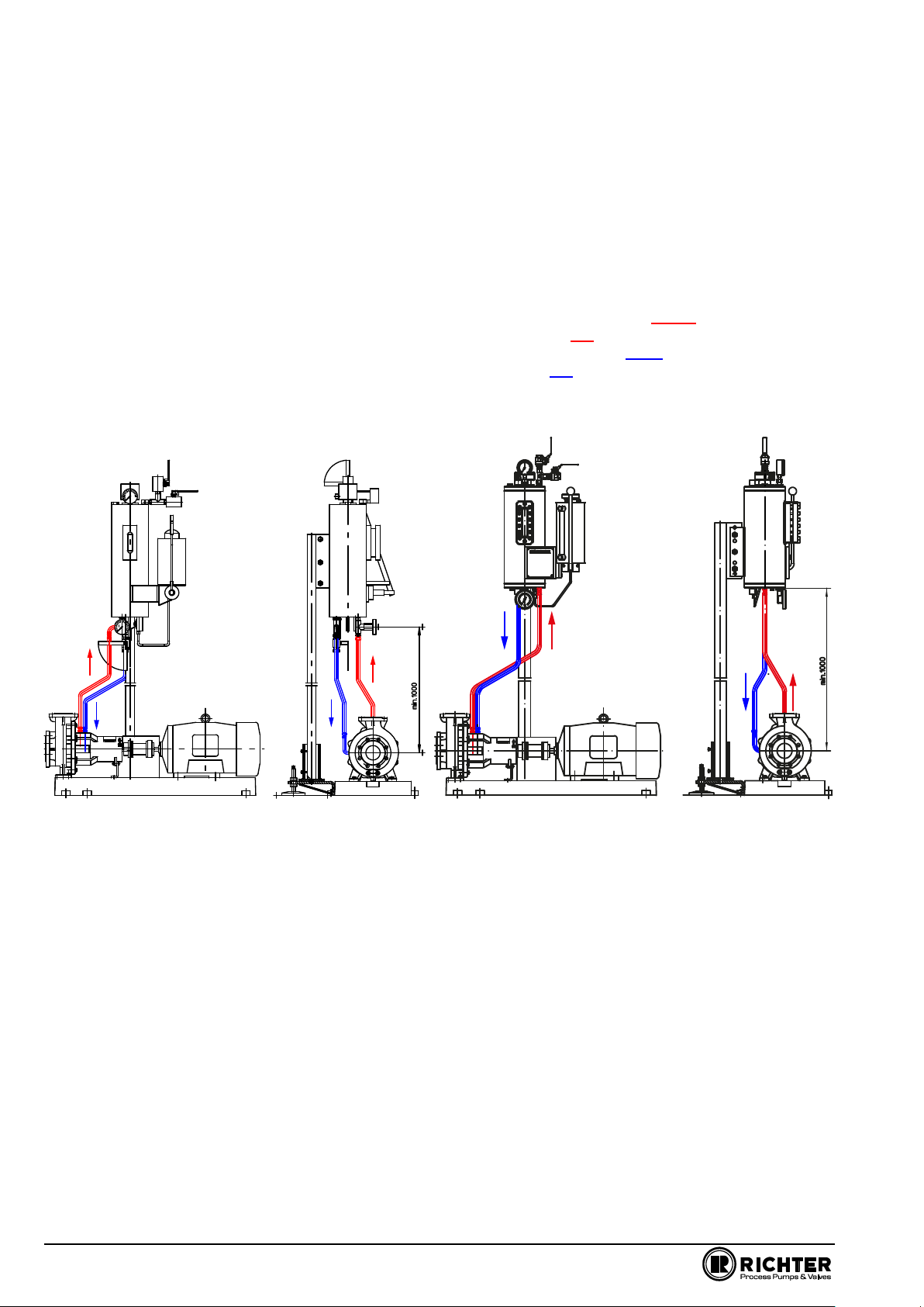
4.2.2 Double mechanical seal to DIN EN 12756....... 3
4.3 Improper operations and their consequences
(examples) ...................................................4
5Maintenance .........................................4
5.1 Dismantling of double mechanical seal to
DIN EN 12756 ............................................. 4
5.1.1 Dismantling of impeller and back plate............ 4
5.1.2 Dismantling the shaft sleeve ........................... 5
5.3 Notes on assembly ..................................... 5
6Malfunctions.........................................7
7Sectional drawing ................................7
7.1 Legend ........................................................ 7
7.2 Double mechanical seal to DIN EN 12756 8
Relevant documents
●Installation and operating manual SCK long life
grease and oil bath lubrication 9220-050-en
●Operating manual mechanical seal of the manufac-
turer
1 Technical data
Manufacturer :
Richter Chemie-Technik GmbH
Otto-Schott-Str. 2
D-47906 Kempen
Telephone: +49 (0) 2152 146-0
Fax: +49 (0) 2152 146-190
E-Mail: [email protected]m
Internet: http://www.richter-ct.com
Authorised person acc. to machinery directive
2006/42/EG: Gregor Kleining
Designation :
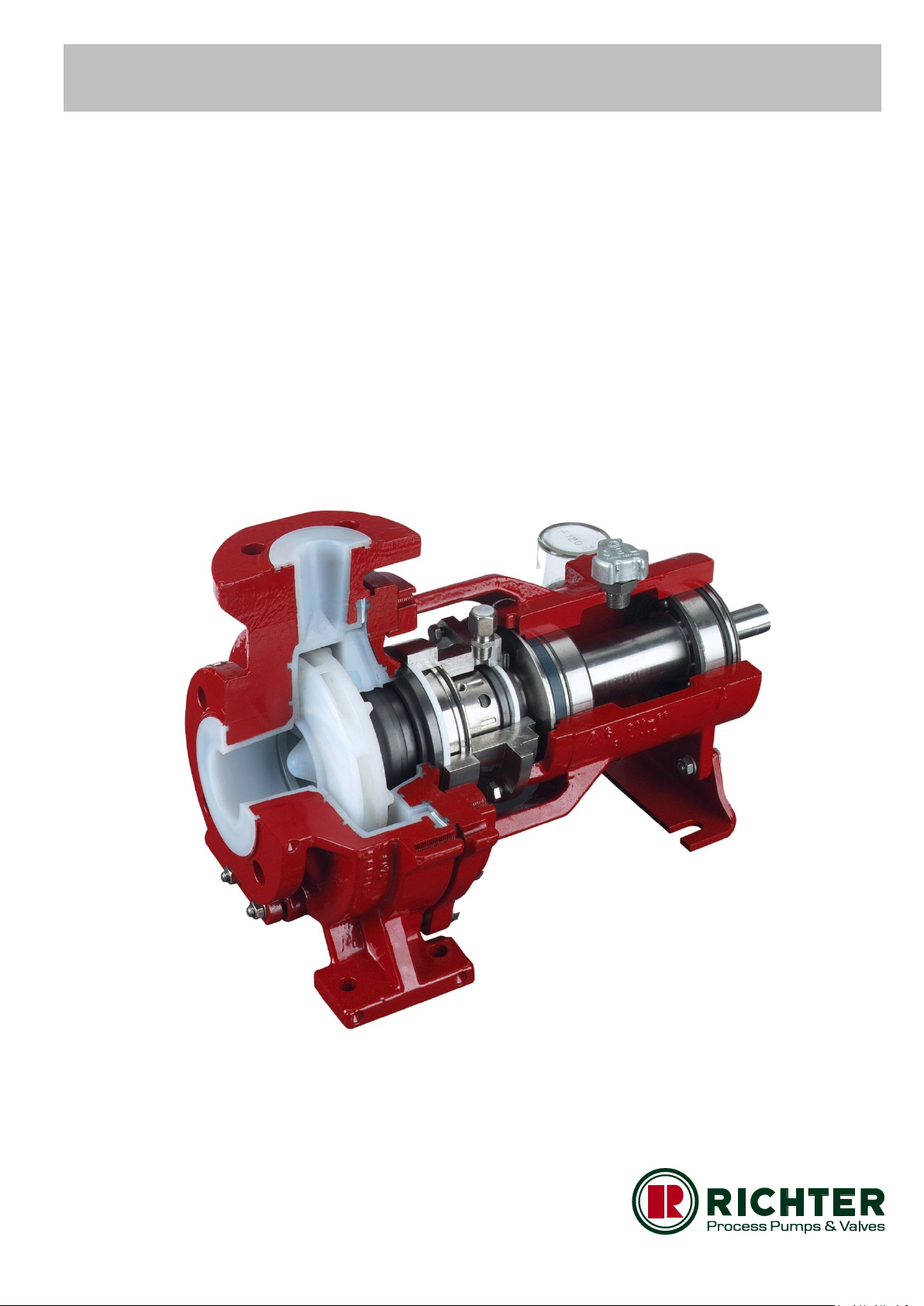
Series SCK, mechanical seal:
●double, to DIN EN 12756
Materials :
Seal housing: Stainless steel
Wetted parts:
Mechanical seal: SSiC, carbon, Al2O3, PTFE, FKM,
FFKM etc., see also data sheet
Temperature range : see installation and
operating manual SCK, Section 1.
Temperature classes : see installation and
operating manual SCK, Section 2.6.7.

Series SCK, double mechanical seal to DIN EN 12756 Page 3
9220-013-en Revision 11
TM 7827 Edition 03/2019
2 Safety, transport, storage and disposal
The relevant sections in the adjacent installation and
operating manuals apply to safety, transport and stor-
age.
This installation and operating manual is only valid in
conjunction with the installation and operating manu-
als of
SCK long life grease and oil bath lubrication9220-050-en
2.1 Intended use
Double mechanical seals for plastic-lined pumps of
the series SCK are suitable for the use of aggressive,
toxic, pure and inflammable media.
The instructions contained in the operating manu-
al or contract documentation must be observed; if
necessary consult the manufacturer.
All important features are documented in the data
sheet included in the scope of delivery.
3 Product description
For a product description of the pump, see the instal-
lation and operating manual of SCK series.
Section 7.2
The sectional drawing shows a double mechanical
seal to DIN EN 12756.
All components which come into contact with the me-
dium are either plastic-lined or made of other resistant
materials, e.g. silicon carbide.
4 Commissioning / Shutdown
4.1 Initial commissioning
See installation and operating manual for the series
SCK.
4.2 Mechanical seals
The design and material combination are specified in
the data sheet.
The proper condition of the components and
the protective facilities must be ensured to
prevent any risk from escaping medium.
The regulations and recommendations of
the mechanical seal manufacturer must
always be observed.
4.2.1 Use in an explosive area
Use in an explosive area means that only
mechanical seals may be employed which
permit observation of temperature.
The operating manual of the respective mechanical
seal manufacturer is an integral part of this general
operating manual.
This permits, amongst other things, the calculation of
the expected surface temperature at the mechanical
seal. The suitability for the permissible temperature
class as per ATEX is hereby given.
Caution!
The permissible temperature class of the complete
unit (pump, mechanical seal, coupling, motor) is de-
termined by the lowest temperature class of the indi-
vidual components.
Example: Pump T4, mechanical seal T3,
coupling T4, motor T4
The unit may only be used in atmospheres which may
ignite above the temperature class T3, i.e. >200 °C.
4.2.2 Double mechanical seal to DIN EN
12756
A pump fitted with a double mechanical seal must
not be filled with a product before the pressurisa-
tion system provided has been started up.
Otherwise damage could occur, e.g. opening of the
wetted sealing gap, before start-up.
To guarantee safe operation, the pressure of the bar-
rier fluid must be 1-2 bar above the pressure of the
process medium at the mechanical seal at Q=0 m3/h.

Series SCK, double mechanical seal to DIN EN 12756 Page 4
9220-013-en Revision 11
TM 7827 Edition 03/2019
It must be ensured that the sealing pressure does not
exceed the admissible pressure of the mechanical
seal used.
The required sealing pressure can be determined as
follows:
2/3 of the delivery pressure at Q = 0 m3/h
+supply pressure
+1 -2 bar safety margin
The supply pressure is measured in bar at the pump
suction nozzle. If no measuring point is available, the
supply pressure can be calculated using the following
formula.
Using the same formula, the delivery pressure at
Q=0 m3/h can be determined with the pump character-
istic curve.
p (bar) = H (mFS) x 𝜌 (kg/dm3 )
10,2
p = supply pressure or delivery pressure
H = supply height or delivery head
= density
Are the available connections correctly
made?
SE - barrier fluid inlet
SA - barrier fluid outlet
See also sectional drawing in Section 7.2
4.3 Improper operations and their
consequences (examples)
Inadmissible modes of operation, even for
brief periods, may result in serious damage
to the unit.
In connection with explosion protection, potential
sources of ignition (overheating, electrostatic and
induced charges, mechanical and electric sparks) may
result from these inadmissible modes of operation;
their occurrence can only be prevented by adhering to
the intended use.
For examples, see installation and operating manual
SCK, Section 6.6.
5 Maintenance
The regulations of the mechanical seal
manufacturer must always be observed.
See also the installation and operating man-
ual for the SCK series.
It is important to replenish in good time any sealing
liquid which has escaped and to monitor the sealing
liquid pressure.
It is important to replenish in good time any sealing
liquid which has escaped and to monitor the sealing
liquid pressure.
Refer also to the description of the pressurisation sys-
tem used and Section 4.2.2.
If the sealing liquid pressure is too high, this indicates
a defect in the mechanical seal even though the
mechanical seal on the atmosphere side is completely
tight.
The pump must then be shut down so that no serious
damage occurs.
Substantial damage generally occurs if the aggressive
process medium enters the pressurisation system as
a result of a drop in the barrier fluid pressure to below
the minimum pressure.
If there is a risk that pressure surges occur in the
plant, precautions must be taken to prevent damage.
To this end, for example, the barrier fluid pressure can
be increased.
5.1 Dismantling of double me-
chanical seal to
DIN EN 12756
Dismantling can be checked using the sectional
drawings in Section 7 and Section 9 of the
installation and operating manual SCK as well as the
components available.
5.1.1 Dismantling of impeller and back
plate
●First of all relieve the mechanical seal by undoing
the attachment screws 901/5.
●Undo screws 901/6 and washers 554/6 of the
bearing pedestal / back plate. Move the back plate
almost up to the impeller with light hammer blows.
●Undo back plate (for instructions, see Sections
4.2.1 and 7.7.4 in the installation and operating
manual SCK).
●Move the back plate almost up to the impeller with
light hammer blows.
●Bearing pedestal group 3:
Labyrinth disc 555 must be secured with
two bolts prior to the dismantling of the
impeller. For this purpose there are 2
bores Ø5mm in the bearing pedestal.
The double mechanical seal is relieved of
pressure as a result. See Dismantling in
Sections 7.7.1 and 7.7.5 in the installa-
tion and operating manual SCK.

Series SCK, double mechanical seal to DIN EN 12756 Page 5
9220-013-en Revision 11
TM 7827 Edition 03/2019
●Undo impeller 230 with a strap wrench or assem-
bly wrench by 1-2 turns. Right-hand thread.
Press the housing cover towards the impeller.
●For assembly aid for impeller, see Section 10.1 in
the installation and operating manual SCK.
●With some pump sizes the work sequence is to be
repeated once or twice so that the cup springs
950/1 can be completely relieved without moving
the shaft sleeve 524 in the rotating units 470 of
the mechanical seal.
●Then completely remove the impeller 230.
●Undo back plate (for instructions, see Sections
4.2.1 and 7.7.4 in the installation and operating
manual SCK).
●It may happen that the mating ring carrier 476 is
removed at the same time as the mating ring
475/1.
●If the mating ring 475/1 is replaced, remove the
anti-torsion insert stud 560/3.
5.1.2 Dismantling the shaft sleeve
●Pull the shaft sleeve 524 with the rotating units
470/1 and 470/2 off the shaft.
●When changing the rotating unit, observe the op-
erating manual of the mechanical seal manufac-
turer.
●Remove seal housing 483.
●Remove mating ring 475/2.
5.2 Notes on assembly
●Only use original spare parts.
●Do not use any defective parts.
●It is essential to observe the assembly and operat-
ing instructions of the pump, pressurisation sys-
tem and mechanical seal manufacturer.
●Bearing pedestal group 3:
Always make sure that when installing
the mechanical seal the labyrinth disc is
secured by 2 bolts.
The bolts must be removed again after assembly
of the impeller.
●If the rotating units are moved by a key, the two
seal halves are to be pushed from both sides onto
the shaft sleeve. Otherwise the secondary seal
would be damaged on the sharp edges of the key
groove.
●PTFE rings are often easier to install if they have
been previously heated in hot water.
●The mating ring carrier 476 is designed with an
anti-torsion insert for the wetted mating ring. It
must be ensured that the mating ring is properly
installed in this device.
●With some mechanical seal types the rotating units
can be better pushed over the shaft sleeve when
dismantled.
●Mount rotating unit 470/2 with pumping thread on
the impeller side.
●The rotating units 470/1 and 470/2 must be flush
with the key 940/2.
●When pushing on the mating ring 475/1, make
sure that the position of the flat section matches
that on the shaft.

Series SCK, double mechanical seal to DIN EN 12756 Page 6
9220-063-en Revision 11
TM 7827 Edition 03/2019
When installing the barrier pressurisation system,
there are some basic things to keep in mind:
●It is essential to observe the installation and oper-
ating instructions of the pump, pressurisation sys-
tem and mechanical seal manufacturer.
●Install the supply system so that operation, moni-
toring and maintenance are easily possible.
●Mount the container above the mechanical seal
(approx. 1 ... 2 m) so that a natural circulation of
the barrier liquid is achieved.
●When supported by a circulation pump, a smaller
distance is possible.
●The pipelines in the circuit of the supply system
should be of stainless steel of the dimensions
specified in the installation and operating instruc-
tions.
●The connections are usually made through pipe
fittings.
●The pipe routing should be as short and stream-
lined as possible.
●To avoid trapped air, lay the pipes in ascending
order.
●For directional changes, use only elbows and shut
off full port ball valves.
●Always connect the discharge line of the mechani-
cal seal to the lateral connection on the reservoir
of the supply system.
The following connection specifications must be
observed:
oMechanical seal OFF connect to supply
system ON.
oSupply system OFF connect with mechanical
seal ON.

Series SCK, double mechanical seal to DIN EN 12756 Page 7
9220-013-en Revision 11
TM 7827 Edition 03/2019
6 Malfunctions
Faults may result from inadmissible modes
of operation. Such improper operation –
even brief ones –may cause serious
damage to the unit.
In connection with explosion protection, potential
sources of ignition (overheating, electrostatic and
induced charges, mechanical and electric sparks)
may result from these inadmissible modes of
operation; their occurrence can only be prevented by
adhering to the intended use.
Should there be any uncertainty about the remedy to
be applied, please inquire at the in-house pump
office or at the pump manufacturer's.
See also Section 8 in the installation and operating
manual of the SCK series.
7 Sectional drawing
7.1 Legend
161 back plate
400/2 flat gasket
412/x O-ring
470/x rotating unit
471 cover seal
475/x mating ring
476 mating ring carrier
483 seal housing
524 shaft sleeve
531/2 spring-type slotted pin
560/3 stud
901/5 hex. screw
917/x screw-in pipe connector
932/5 Circlip
940/3 key
SE - barrier fluid inlet
SA - Barrier liquid outlet or emptying

Series SCK, double mechanical seal to DIN EN 12756 Page 8
9220-063-en Revision 11
TM 7827 Edition 03/2019
7.2 Double mechanical seal to DIN EN 12756
View displaced by 90°

Richter™ = Richter Chemie-Technik GmbH; IDEX™ = IDEX Corporation
Richter Chemie-Technik GmbH
Otto-Schott-Str. 2
D-47906 Kempen / Germany
Tel: +49 (0) 2152 146-0
Fax: +49 (0) 2152 146-190
Email: Richter-Info@idexcorp.com
Internet: www.richter-ct.com
Richter (EP), Nanjing, Shanghai Office
Room 3502 - 3504, Zhaofeng Plaza
No. 1027, Changning Road, Shanghai 200050 / China
Tel: +86 / 21 / 6150 - 9812
Fax: +86 / 21 / 5241 - 2870
Email: RichterShanghai-Info@idexcorp.com
Internet: www.richter-ct.com
Richter Pumps & Valves, Inc.
406 State Street,
Cedar Falls 50613, IA / USA
Tel.: +1 / 319 / 268 - 8038
Fax: +1 / 319 / 273 - 8157
Internet: www.richter-inc.com
Richter Pumps & Valves Pvt. Ltd.
Suntech Centre, 37-40, Subhash Road
Vile Parle East, Mumbai 400057 / India
Tel: +91 / 22 / 287 94 610
Fax: + 91 / 22 / 287 94 680
Email: RichterMumbai-Info@idexcorp.com
Internet: www.richter-ct.com
© Richter Chemie-Technik GmbH 2019
Subject to change without notice.
Edition 03/2020
Revision 0,0
9220B013-en
Other manuals for SCK Series
4
Table of contents
Other Richter Industrial Equipment manuals