Richter SGS/F Series User manual

INSTALLATION AND OPERATING MANUAL
Keep for future use!
This operating manual must be strictly observed before
transport, installation, operation and maintenance
Subject to change without notice.
Reproduction is generally permitted with indication of the source.
© Richter Chemie-Technik GmbH.
9540-005-en Revision 13 Edition 11/2018
Series SGS/F
Richter
2-way cylindrical sight glass

Series SGS/F Page 2
9540-005-en Revision 13
TM 9549 Edition 11/2018
List of Contents
List of Contents ................................................ 2
Relevant documents ........................................ 2
1Technical data............................................. 2
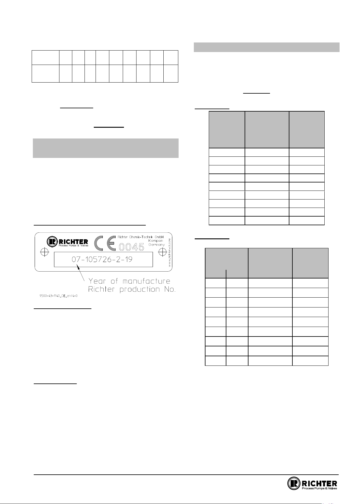
1.1 Type plate, CE and body markings..............3
1.2 Tightening torques...........................................3
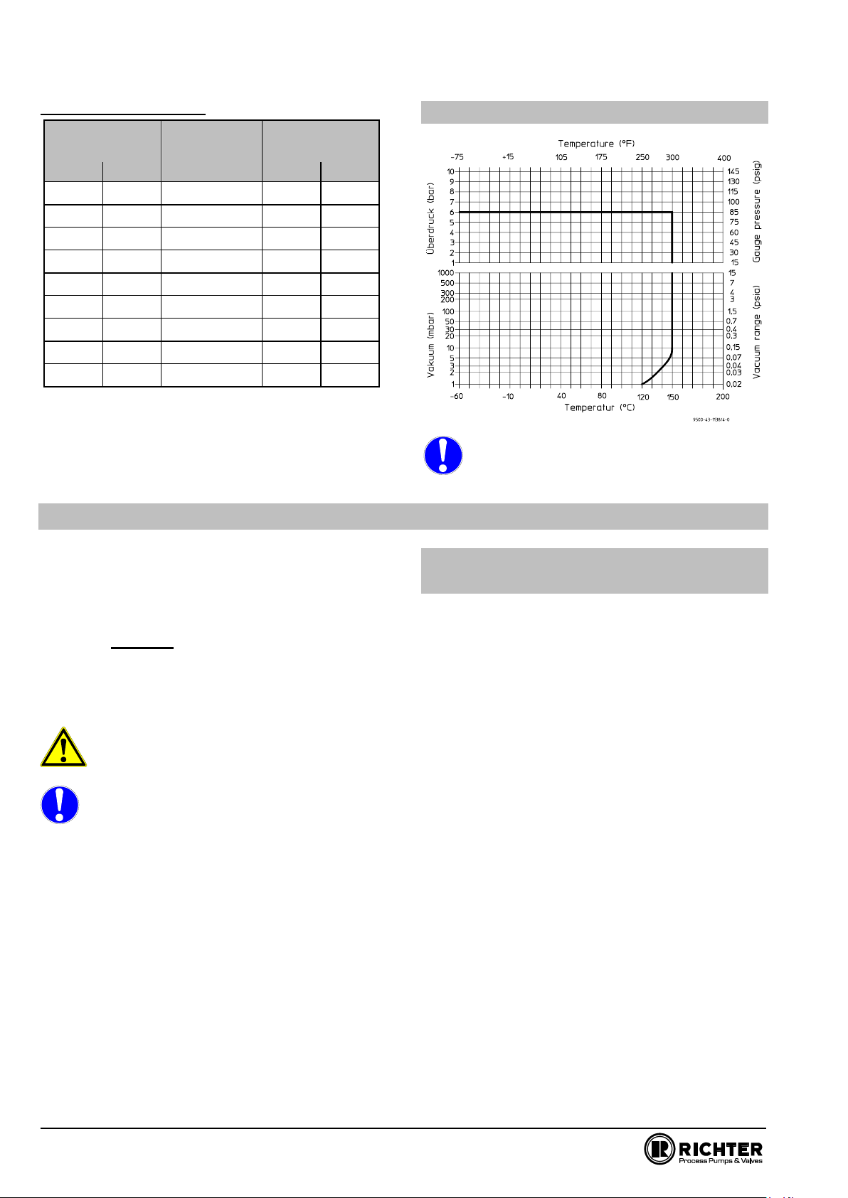
1.3 Pressure-temperature diagram .....................4
2Notes on safety ........................................... 4
2.1 Intended use ...................................................4
2.2 For the customer / operator ...........................5
2.3 Improper operation ..........................................5
3Safety notes for applications in potentially
explosive areas based on the Directive
2014/34/ EC (ATEX)..................................... 5
3.1 Intended use.....................................................5
4Safety note for valves, certified to Clean
Air Act (TA-Luft).......................................... 6
5Transport and storage ............................... 6
5.1 Storage.............................................................. 6
5.2 Return consignments ...................................... 6
5.3 Disposal ............................................................7
6Installation ................................................... 7
6.1 Flange caps and gaskets................................7
6.2 Direction of flow and installation position .....7
6.3 Grounding .........................................................7
6.4 Test pressure ...................................................7
7Operation ..................................................... 7
7.1 Initial commissioning .......................................7
7.2 Improper operation and their consequences7
7.3 Shutdown ..........................................................8
8Malfunctions ................................................ 8
9Maintenance ................................................ 8
9.1 Dismantling the cylindrical sight glass.........8
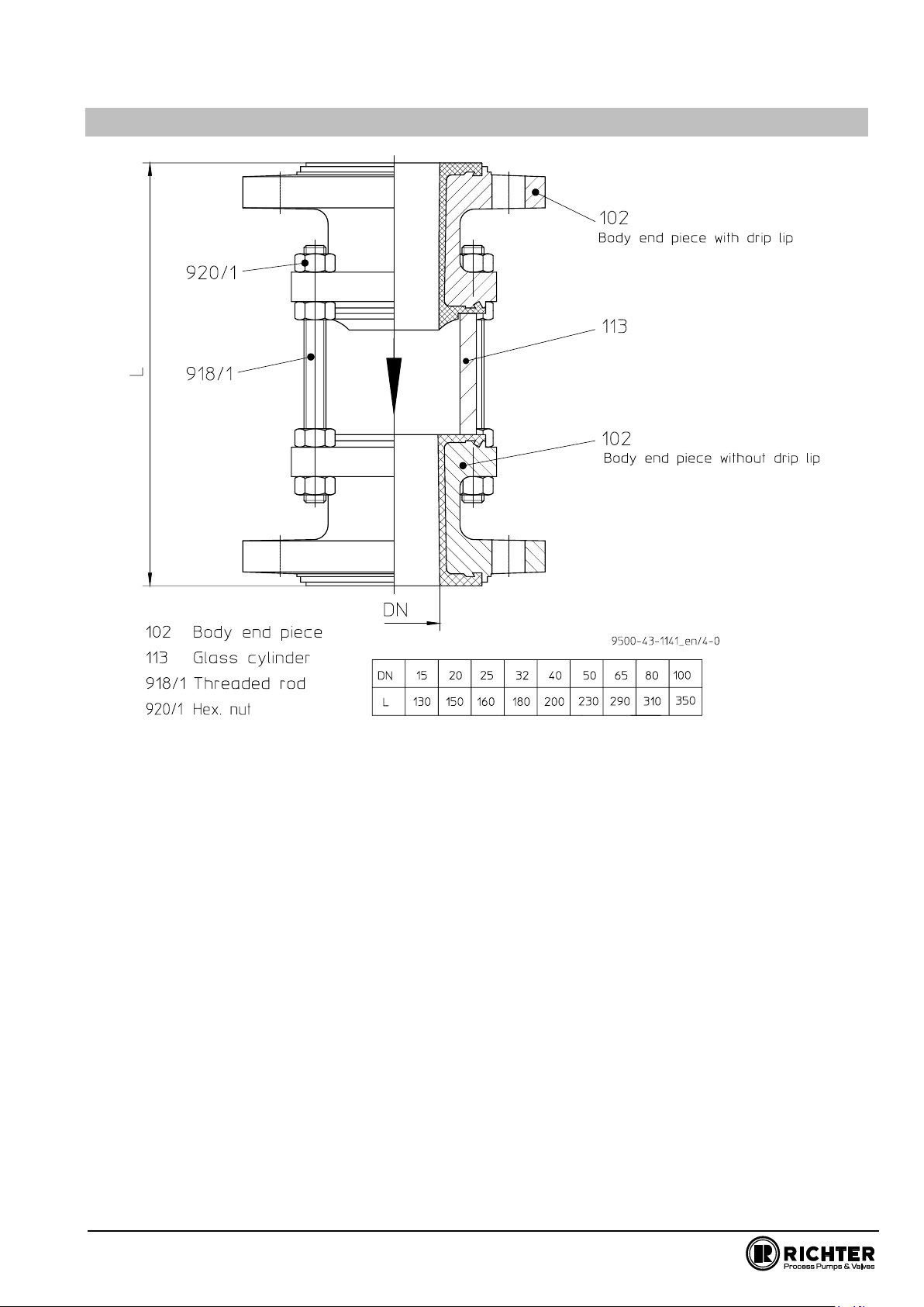
10 Sectional drawing ....................................... 9
Relevant documents
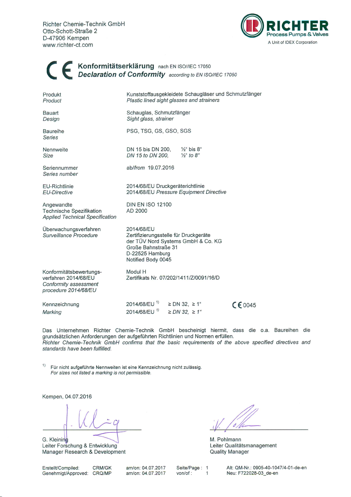
♦EG-Declaration of conformity
♦Declaration of conformity FDA & 97/48/EG
♦Manufacturer Declaration ATEX Directive
2014/34/EU
♦Manufacturer Declaration TA-Luft
♦Form for Safety Information Concerning the
Contamination QM 0912-16-2001_en
1 Technical data
Manufacturer:
Richter Chemie-Technik GmbH
Otto-Schott-Str. 2
D-47906 Kempen
Telephone: +49 (0) 2152 146-0
Fax: +49 (0) 2152 146-190
E-Mail: richter-info@richter-ct.com
Internet: http://www.richter-ct.com
Designation :
2-way Cylindrical Sight Glass, series SGS/F
Certified to Clean Air Act (TA Luft)
Strength and tightness (P10, P11) of the pressure-
bearing body tested to DIN EN 12266-1.
Flange connecting dimensions:
DIN EN 1092-2, type B
(ISO 7005-2 type B) PN 16
or flanges drilled to ANSI B16.5 Class 150
Face to face: DIN EN 558-1, basic series 1
(ISO 5752 basic series 1)
optionally face to face acc. to specifications
Materials :
Body material: Ductile cast iron EN-JS 1049 /
Lining material: PFA
on request non-conductive design
Glass cylinder: borosilicate glass
Temperature range : -60 °C to +150 °C
See pressure-temperature diagram in Section 1.3.
Operating pressure : from vacuum to max. 6 bar
See pressure-temperature diagram in Section 1.3.
Valve size :
DN 15, 20, 25, 32, 40, 50, 65, 80, 100

Series SGS/F Page 3
9540-005-en Revision 13
TM 9549 Edition 11/2018
Weight:
Nom.
size
15
20
25
32
40
50
65
80
100
approx.
kg
3
3
4
5
8
10
13
20
30
Installation position :
A direction arrow on the shell indicates the direction of
flow. See Section 6.2.
Dimensions and individual parts:
See sectional drawing Section 10.
1.1 Type plate, CE and
body markings
The stainless steel name plate is firmly riveted to the
body.
If the operator attaches his identification, it must be
ensured that the valve matches the application in
question.
No CE marking is permissible for the sizes 15, 20 and
25; the name plate therefore has no CE marking.
Example of type plate with CE marking:
Body identification :
The following are visible on the body according to DIN
EN 19 and AD 2000 A4:
♦Nominal size
♦Rated pressure
♦Body material
♦Manufacturer's identification
♦Melt number/Foundry identification
♦Cast date
Glass cylinder:
♦Company name
♦Operating gauge pressure
♦Temperature
♦Arrow for direction of flow
1.2 Tightening torques
All screws greased, tighten in diametrically
opposite sequence!
The tightening torques for pipe screws and cylindrical
glass screws mentioned must not be exceeded. For
an exception, see Section 8.
The following tightening torques are recommended.
Pipe screws, flanges to ISO/DIN
Flange
Nominal
size
screws
Tightening
torque
[mm]
[DIN]
[Nm]
15
4 x M12
12
20
4 x M12
12
25
4 x M12
12
32
4 x M16
18
40
4 x M16
22
50
4 x M16
30
65
4 x M16
40
80
8 x M16
25
100
8 x M16
30
Pipe screws, flanges ISO/DIN
drilled to ASME
Flange
Nominal size
screws
Tightening
torque
[mm]
[inch]
[ASME]
[in-lbs]
15
½
4 x ½“
106
20
¾
4 x ½“
106
25
1
4 x ½“
106
32
1¼
4 x ½“
106
40
1½
4 x ½“
133
50
2
4 x ⅝“
221
65
2½
4 x ⅝“
266
80
3
4 x ⅝“
354
100
4
8 x 5/8“
266

Series SGS/F Page 4
9540-005-en Revision 13
TM 9549 Edition 11/2018
Cylindrical glass screws
Flange
Nominal size
screws
Tightening
torque
[mm]
[inch]
[ISO/DIN]
[Nm]
[in-lbs]
15
½
4 x M8
10
89
20
¾
4 x M8
10
89
25
1
4 x M8
15
133
32
1¼
4 x M8
15
133
40
1½
4 x M12
25
222
50
2
4 x M12
35
310
65
2½
4 x M12
35
310
80
3
8 x M16
60
531
100
4
8 x M16
60
531
1.3 Pressure-temperature diagram
When used in the minus temperature range,
the regulations applicable in the country in
question must be observed.
2 Notes on safety
This operating manual contains fundamental
information which is to be observed during installation,
operation and maintenance. It must be read before
installation and commissioning!
For valves which are used in potentially explosive
areas, see Section 3.
Installation and operation are to be performed by
qualified staff.
The area of responsibility, authority and supervision of
the staff must be regulated by the customer.
General hazard symbol!
People may be put at risk.
Safety symbol! The cylindrical sight glass
and its function may be put at risk if this
safety symbol is not observed.
It is imperative to observe warnings and signs
attached directly to the cylindrical sight glass and they
are to be kept fully legible.
Non-observance of the notes on safety may result
in the loss of any and all claims for damages.
For example, non-observance may involve the
following hazards:
♦Failure of important functions of the valve/plant.
♦Risk to people from electric, mechanical and
chemical effects.
♦Risk to the environment through leaks of
hazardous substances.
2.1 Intended
use
Richter sight glasses of the series SGS/F are
pressure relief components in accordance with the
Pressure Equipment Directive (PED) for the passage
of fluids with all-round vision into the internal chamber.
The valves are suitable for vapours, gases and liquids
of group 1 in accordance with the PED and have a
corrosion-resistant plastic lining.
They are used to observe the flow, filling level,
condition, colour and gas contents of media in pipes
and containers and near pumps.
Richter sight glasses are designed
♦for pure and slightly solids-laden media
♦for media where stainless steel is not corrosion-
resistant
♦as an alternative to valves made of expensive
special metals (Hastelloy, monel, tantalum etc.)
♦for metal-reactive media, e.g. H2O2
♦for pure media where the good cleaning possibili-
ties and anti-adhesive surfaces of the sight glass
are important.
Solids can lead to increased wear, leaks, damage to
sealing surfaces or to a reduction in the service life of
the sight glass.
The operator must carefully examine in the event of
operating data other than those provided whether the
designs of the valve, accessories and materials are
suitable for the new application (consult the manufac-
turer).

Series SGS/F Page 5
9540-005-en Revision 13
TM 9549 Edition 11/2018
2.2 For the customer / operator
When using the cylindrical sight glass, it must be
ensured that
♦hot or cold valve parts are protected by the
customer against being touched
♦the sight glass has been properly installed in the
pipe system
♦the usual flow rates are not exceeded in continu-
ous operation.
This is not the manufacturer's responsibility.
Loads caused by earthquakes were not allowed for in
the design.
Fire protection to DIN EN ISO 10497 is not possible
(plastic lining and plastic components).
2.3 Improper operation
The operational reliability of the cylindrical sight glass
supplied is only guaranteed if it is used properly in
accordance with Section 2.1 of this operating manual.
The operation limits specified on the name
plate and in the pressure-temperature
diagram must under no circumstances be
exceeded.
3 Safety notes for applications in potentially explosive areas
based on the Directive 2014/34/ EC (ATEX)
The valves are intended for use in a potentially
explosive area and are therefore subject to the
conformity assessment procedure of the directive
2014/34/EC (ATEX).
As part of this conformity assessment, an ignition
hazard analysis to EN 13463-1 to satisfy the
fundamental safety and health requirements was
conducted with the following result:
♦The valves do not have any ignition source of
their own.
♦The valves are not covered by the scope of
application of the ATEX directive and therefore
do not need to be identified accordingly.
♦The valves may be used in a potentially
explosive area.
It is imperative to observe the individual points of
intended use for application in a potentially explosive
area.
3.1 Intended use
Improper operation, even for brief periods, may
result in serious damage to the valve.
In connection with explosion protection, potential
sources of ignition (overheating, electrostatic and
induced charges, mechanical and electric sparks)
may result from these improper operation; their
occurrence can only be prevented by adhering to
the intended use.
Furthermore, reference is made in this connection to
the Directive 95/C332/06 (ATEX 118a) which contains
the minimum regulations for improving the occupa-
tional health and safety of the workers who may be at
risk from an explosive atmosphere.
A difference is made between two cases for the use of
chargeable liquids (conductivity < 10-8 S/m):
1. Chargeable liquid and non-conductive lining
Charges can occur on the lining surface. As a
result, this can produce discharges inside and
outside the valve.
a) Discharges inside the valve
However, these discharges inside the valve cannot
cause ignitions if the valve is completely filled with
medium.
If the valve is not completely filled with medium,
e.g. during evacuation and filling, the formation of
an explosive atmosphere must be prevented, e.g.
by superimposing a layer of nitrogen. It is recom-
mended to wait 1 hour before removing the valve
from the plant in order to permit the elimination of
static peak charges.
This means that, to safely prevent ignitions, the
valve must be completely filled with medium at all
times or else a potentially explosive atmosphere
must be excluded by superimposing a layer of inert
gas.
b) Discharges outside the valve
At the points where the non-conductive lining e.g.
protrudes on the sealing surfaces to the outside or
gets contact with the atmosphere on the outside, it
may lead to discharges from the lining to nearby
valves or attachments.
To safely avoid explosion hazards and accidents,
therefore, the atmosphere surrounding the valve
must not be explosive.
2. Chargeable liquid and conductive lining

Series SGS/F Page 6
9540-005-en Revision 13
TM 9549 Edition 11/2018
No hazardous charges can occur as charges are
discharged direct via the lining and shell (surface
resistance < 109Ohm, leakage resistance < 106
Ohm)
Static discharges of non-conductive linings are
only produced through the interaction with a
non-conductive medium and are therefore the
responsibility of the plant operator.
Static discharges are not sources of ignition
which stem from the valves themselves!
♦The temperature of the medium must not exceed
the temperature of the corresponding temperature
class or the maximum admissible medium tem-
perature as per the operating manual.
♦If the valve is heated (e.g. heating jacket), it must
be ensured that the temperature classes pre-
scribed in the Annex are observed.
♦To achieve safe and reliable operation, it must
be ensured in inspections at regular intervals that
the valve is properly serviced and kept in techni-
cally perfect order.
♦Increased wear to the valve can be expected with
the conveyance of liquids containing abrasive
constituents. The inspection intervals are to be
reduced compared with the usual times.
♦Actuators and electric peripherals, such as
temperature, pressure and flow sensors etc., must
comply with the valid safety requirements and
explosion protection provisions.
♦The valve must be grounded.
This can be achieved in the simplest way via the
pipe screws using tooth lock washers.
Otherwise grounding must be ensured by different
measures e.g. a cable link.
Plastic-lined valves must not be operated with carbon
disulphide.
4 Safety note for valves, certified to Clean Air Act (TA-Luft)
Certificate / Manufacturer Declaration Validity is
dependent on the operating instructions being read
and observed.
♦Carry out regular maintenance intervals and
check the tightness of the screw connections and
tighten as necessary.
5 Transport and storage
It is imperative, for all transport work, to
observe generally accepted engineering
practice and the accident prevention
regulations.
The cylindrical sight glass is supplied with
flange caps. Do not remove them until just
before installation. They protect the plastic
surfaces against dirt and mechanical
damage.
Handle the goods being transported with care. During
transport the valve must be protected against impacts
and collisions.
Directly after receipt of the goods, the consignment
must be checked for completeness and any in-transit
damage.
Do not damage paint protection.
5.1 Storage
If the sight glass is not installed immediately after
delivery, it must be put into proper storage.
It should be stored in a dry, vibration-free and well-
ventilated room at as constant a temperature as
possible.
Elastomers are to be protected against UV light.
In general, a storage period of 10 years should not be
exceeded.
5.2 Return consignments
Valves which have conveyed aggressive or toxic
media must be well rinsed and cleaned before being
returned to the manufacturer's works.
It is imperative to enclose a safety information
sheet / general safety certificate on the field of
application with the return consignment.
Pre-printed forms are enclosed with the installation
and operating manual.
Safety precautions and decontamination methods are
to be mentioned.

Series SGS/F Page 7
9540-005-en Revision 13
TM 9549 Edition 11/2018
5.3 Disposal
Parts of the valve may be contaminated with medium
which is detrimental to health and the environment
and therefore cleaning is not sufficient.
Risk of personal injury or damage to the
environment due to the medium!
♦Wear protective clothing when work is performed
on the valve.
♦Prior to the disposal of the valve:
▪Collect any medium, etc. which has es-
caped and dispose of it in accordance with
the local regulations.
▪Neutralise any medium residues in the
valve.
♦Separate valve materials (plastics, metals, etc.)
and dispose of them in accordance with the local
regulations.
6 Installation
♦Examine valve for in-transit damage, damaged
globe shut-off or control valves must not be in-
stalled.
♦Before installation the valve and the connecting
pipe must be carefully cleaned to remove any dirt,
especially hard foreign matter.
♦During installation, pay attention to the correct
tightening torque, aligned pipes and tension-free
assembly.
6.1 Flange caps and gaskets
Leave protective caps on the flanges until just prior to
installation.
Where there is a particularly high risk of damage to
the plastic sealing surfaces, e.g. if the mating flanges
are made of metal or enamel, PTFE-lined gaskets
with a metal inlay should be used. These gaskets are
available as special accessories in the Richter range.
6.2 Direction of flow and installa-
tion position
The direction of flow must be observed
when installing the valve.
It is indicated by a direction arrow on the glass
cylinder.
6.3 Grounding
Additional grounding of the sight glass is
unnecessary. All internal parts are in contact with
conductive media.
6.4 Test pressure
The test pressure PT of a valve must not exceed the
value of 1.5 x PS(PN) as per the identification of the
valve.
7 Operation
7.1 Initial commissioning
Normally, the valves have been tested for leaks with
air or water.
Unless otherwise agreed there could be residual
amounts of water in the flow section of the valve. This
could result in a possible reaction with the medium.
To prevent leaks, all connection screws should be
retightened after the initial loading of the valve with
operating pressure and operating temperature.
For tightening torques, see Section 1.2.
7.2 Improper operation and their
consequences
♦Avoid excessive dirt as otherwise high pressure
losses or damage to the sight glass could occur.
♦Non-observance of the pressure-temperature
diagram can lead to damage.

Series SGS/F Page 8
9540-005-en Revision 13
TM 9549 Edition 11/2018
7.3 Shutdown
The local regulations are to be observed when
dismantling the valve.
Before loosening the flange bolts:
♦ensure plant to be free of pressure
♦flush out medium
♦observe safety regulations
Prior to starting any repair work, the valve is
to be thoroughly cleaned. Medium residue
may be in the valve even if it has been
properly drained and flushed.
After dismantling, immediately protect the valve
flanges against mechanical damage by using flange
caps.
See also Section 6.1.
8 Malfunctions
♦Flange connection sight glass/pipe is leaking
Check the torque of the pipe screws with a torque
wrench (see Section 1.2). If tightness is not
achieved, the recommended torque may be ex-
ceeded by 10%.
If it still proves impossible to stop the leak, then
the lining is damaged. Dismount valve and repair.
♦Flange connection end piece/glass cylinder is
leaking
Undo hex. nuts on the side towards the glass
cylinder.
Retighten hex. nuts on the outside in diametrically
opposite sequence.
If there is still a leak, the recommended tightening
torques may be exceeded by 10%. Counter with
hex. nuts on the inside.
9 Maintenance
♦During dismantling and assembly work, observe
the information and drawings in Sections 1 and
10.
♦All repair work is to be performed by qualified
personnel using the appropriate tools.
♦For the arrangement, designation and item
numbers of all parts of the valve, see Section 10.
♦Spare parts are to be ordered with all the details
in acc. with the valve identification.
♦Only original spare parts may be installed.
♦To prevent leaks, a regular check of the connec-
tion screws should be made in line with the oper-
ating requirements.
For tightening torques, see Section 1.2.
9.1 Dismantling the
cylindrical sight glass
♦Undo end piece nuts and remove the end piece.
During re-assembly, ensure that all nuts are tight-
ened evenly.
It is essential to ensure that the glass cylinder is
subjected to uniform loading.
For tightening torques, see Section 1.2.

Series SGS/F Page 9
9540-005-en Revision 13
TM 9549 Edition 11/2018
10 Sectional drawing


QM 0927-04-1001/4-16
Richter Chemie-Technik
GmbH Telefon + 49 (0) 21 52 / 146- 0
J.P.
Morgan AG,
Frankfurt/Main
·
Kto. Nr.
6
161
507
538 (BLZ
501
108
00)
Otto-Schott-Straße
2Telefax + 49 (0) 21 52 / 146- 190
BIC/SWIFT: CHASDEFX
·
IBAN Code: DE61 5011 0800 6161 5075 38
D-47906
Kempen [email protected]m
Sitz
der
Gesellschaft: Kempen
·
Amtsgericht Krefeld
HRB
9635
USt. Id. Nr. DE 811 127 054
www.richter-ct.com
Geschäftsführer:
Barbara Wladarz, Bret A.Prybylski
Richter Chemie-Technik GmbH
·
Postfach 10
06
09
·
D-47883
Kempen
08.01.2015
Declaration of no objection
Dear Sirs,
The compliance with laws for the industrial safety obligates all commercial enterprises to protect their employees
and/or humans and environment against harmful effects while handling dangerous materials.
The laws are such as: the Health and Safety at Work Act (ArbStättV), the Ordinance on Harzadous Substances
(GefStoffV, BIOSTOFFV), the procedures for the prevention of accidents as well as regulations to environmental
protection, e.g. the Waste Management Law (AbfG) and the Water Resources Act (WHG)
An inspection/repair of Richter products and parts will only take place, if the attached explanation is filled out cor-
rectly and completely by authorized and qualified technical personnel and is available.
In principle, radioactively loaded devices sent in, are not accepted.
Despite careful draining and cleaning of the devices, safety precautions should be necessary however, the essen-
tial information must be given.
The enclosed declaration of no objection is part of the inspection/repair order. Even if this certificate is available,
we reserve the right to reject the acceptance of this order for other reasons.
Best regards
RICHTER CHEMIE-TECHNIK GMBH

Prepared: CRQ/Lam on:Nov. 13, 2006 Page: 1 QM-Nr.: 0912-16-2001_en/4-07
Approved: CRQ/Zu on:Nov. 13, 2006 of :2
Safety Information / Declaration of No Objection Concerning the Contamination
of Richter-Pumps, -Valves and Components
1 SCOPE AND PURPOSE
Each entrepreneur (operator) carries the responsibility for the health and safety of his
employees. This extends also to the personnel, who implements repairs with the operator or
with the contractor.
Enclosed declaration is for the information of the contractor concerning the possible
contamination of the pumps, valves and component sent in for repair. On the basis of this
information for the contractor is it possible to meet the necessary preventive action during
the execution of the repair.
Note: The same regulations apply to repairs on-site.
2 PREPARATION OF DISPATCH
Before the dispatch of the aggregates the operator must fill in the following declaration
completely and attach it to the shipping documents. The shipping instructions indicated in the
respective manual are to be considered, for example:
•Discharge of operational liquids
•remove filter inserts
•lock all openings hermetically
•proper packing
•Dispatch in suitable transport container
•Declaration of the contamination fixed outside!! on the packing

Declaration about the Contamination of
Richter Pumps, -Valves
and Components
Prepared: CRQ/Lam on:Nov. 13, 2006 Page: 2 QM-Nr.: 0912-16-2001_de/4-07
Approved: CRQ/Zu on:Nov. 13, 2006 of :2
The repair and/or maintenance of pumps, valves and components can only be implemented if a completely filled out declaration is
available. If this is not the case, delay of the work will occur. If this declaration is not attached to the devices, which have to be
repaired, the transmission can be rejected.
Every aggregate has to have it’s own declaration.
This declaration may be filled out and signed only by authorized technical personnel of the operator.
Contractor/dep./institute :
Reason for transmitting Please mark the applicable
Repair: subject to fee Warranty
Street :
Austausch: subject to fee Warranty
Postcode, city :
Exchange/ Replacement already initiated/received
Contact person :
Return: Leasing Loan for credit note
Phone : Fax :
End user :
A. Details of Richter-product:
Failure description:
Classification:
Article number:
Serial number:
B. Condition of the Richter-
product:
no1)
yes no
Contamination :
no1) yes
Was it in operation ?
toxic
Drained (product/operating supply item) ?
caustic
All openings hermetically locked!
inflammable
Cleaned ?
explosive2)
If yes, with which cleaning agent:
mikrobiological2)
and with which cleaning method:
radioactive3)
1) if "no", then forward to D.
other pollutant
2) Aggregates, which are contaminated with microbiological or explosive substances, are only accepted with
documented evidence of an approved cleaning.
3) Aggregates, which are contaminated with radioactive substances, are not accepted in principle.
C. Details of the discharged materials (must be filled out imperatively)
1.
With which materials did the aggregate come into contact ? Trade name and/or chemical designation of
operational funds and discharged materials, material properties, e.g. as per safety data sheet (e.g. toxic,
inflammable, caustic)
X Trade name:
Chemical designation:
a)
b)
c)
d)
no yes
2.
Are the materials specified above harmful to health ?
3.
Dangerous decomposition products during thermal load ?
If yes, which ones?
D. Mandatory declaration: We assure that the data in this explanation are truthful and complete and as a signatory I am able
to form an opinion about this. We are aware that we are responsible towards the contractor for damages, which results from
incomplete and incorrect data. We commit ourselves to exempt the contractor from claims for damages of thirds resulting from
incomplete or incorrect data. We are aware that we are directly responsible towards thirds, irrespective of this declaration,
which belongs in particularly to the employees of the contractor consigned with the handling repair of the product.
Company stamp
Name of the authorized person
(in block letters):
Date
Signature

Richter™ = Richter Chemie-Technik GmbH; IDEX™ = IDEX Corporation
Richter Chemie-Technik GmbH
Otto-Schott-Str. 2
D-47906 Kempen / Germany
Tel: +49 (0) 2152 146-0
Fax: +49 (0) 2152 146-190
Internet: www.richter-ct.com
Richter (EP), Nanjing, Shanghai Office
Room 3502 - 3504, Zhaofeng Plaza
No. 1027, Changning Road, Shanghai 200050 / China
Tel: +86 / 21 / 6150 - 9812
Fax: +86 / 21 / 5241 - 2870
Email: RichterShanghai-Info@idexcorp.com
Internet: www.richter-ct.com
Richter Pumps & Valves, Inc.
406 State Street,
Cedar Falls 50613, IA / USA
Tel.: +1 / 319 / 268 - 8038
Fax: +1 / 319 / 273 - 8157
Email: RichterCedarFalls-Info@idexcorp.com
Internet: www.richter-inc.com
Richter Pumps & Valves Pvt. Ltd.
Suntech Centre, 37-40, Subhash Road
Vile Parle East, Mumbai 400057 / India
Tel: +91 / 22 / 287 94 610
Fax: + 91 / 22 / 287 94 680
Email: RichterMumbai-Info@idexcorp.com
Internet: www.richter-ct.com
© Richter Chemie-Technik GmbH 2019 Edition 03/2020
Subject to change without notice. Revision 0,0
9540B005-en
Table of contents
Other Richter Industrial Equipment manuals