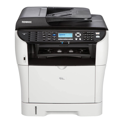
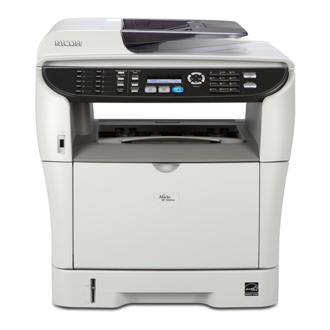
Ricoh SP 230SFNw User manual

Confidential
Read this manual thoroughly before maintenance work.
Keep this manual in a convenient place for quick and easy reference at all times.
August 2017
SM-FAX194
8C5K*
Ver.1
SERVICE MANUAL
SP 230SFNw
MODEL

Confidential
Trademarks
Microsoft and Windows are registered trademarks of Microsoft Corporation in the United States and/or
other countries.
Apple and Mac are trademarks of Apple Inc., registered in the U.S. and other countries.
AirPrint and the AirPrint logo are trademarks of Apple Inc.
App Store is a service mark of Apple Inc.
Wi-Fi is a registered trademark of Wi-Fi Alliance®.
Android is a trademark of Google Inc.
Google Play is a trademark of Google Inc.
Mopria®and the Mopria®Logo are registered trademarks and service marks of Mopria Alliance, Inc. in
the United States and other countries. Unauthorized use is strictly prohibited.
Each company whose software title is mentioned in this manual has a Software License Agreement
specific to its proprietary programs.
Software Trademarks
FlashFX®is a registered trademark of Datalight, Inc.
FlashFX®Pro™ is a trademark of Datalight, Inc.
FlashFX®Tera™ is a trademark of Datalight, Inc.
Reliance™ is a trademark of Datalight, Inc.
Reliance Nitro™ is a trademark of Datalight, Inc.
Datalight®is a registered trademark of Datalight, Inc.

Confidential
Copyright and License
This product includes software developed by the following vendors:
©1983-1998 PACIFIC SOFTWORKS, INC. ALL RIGHTS RESERVED.
©2008 Devicescape Software, Inc. All rights reserved.
This product includes the “KASAGO TCP/IP” software developed by ZUKEN ELMIC, Inc.
Copyright 1989-2014 Datalight, Inc., All Rights Reserved.
FlashFX®Copyright 1998-2014 Datalight, Inc.
U.S.Patent Office 5,860,082/6,260,156

iConfidential
CONTENTS
SAFETY INFORMATION ...........................................................................................vi
CHAPTER 1 SUPPLEMENTAL SPECIFICATIONS
1. GENERAL ................................................................................................................................... 1-1
2. NETWORK CONNECTIVITY ....................................................................................................... 1-2
3. SERVICE INFORMATION ........................................................................................................... 1-3
4. MEDIA SPECIFICATIONS .......................................................................................................... 1-4
5. FAX .............................................................................................................................................. 1-5
6. COPY ........................................................................................................................................... 1-6
7. SCANNER ................................................................................................................................... 1-7
CHAPTER 2 ERROR INDICATIONS AND TROUBLESHOOTING
1. INTRODUCTION ......................................................................................................................... 2-1
1.1 Precautions ......................................................................................................................... 2-1
1.2 Checks before Commencing Troubleshooting .................................................................... 2-3
2. OVERVIEW ................................................................................................................................. 2-5
2.1 Cross-section Drawing ........................................................................................................ 2-5
2.1.1 Printer part .............................................................................................................. 2-5
2.1.2 Scanner part ........................................................................................................... 2-6
2.2 Paper Feeding .................................................................................................................... 2-7
2.2.1 Printer part .............................................................................................................. 2-7
2.2.2 Scanner part ........................................................................................................... 2-8
2.3 Operation of Each Part and Location of Parts .................................................................... 2-9
2.4 Block Diagram .................................................................................................................. 2-11
2.5 Main Components ............................................................................................................. 2-12
3. ERROR INDICATIONS .............................................................................................................. 2-14
3.1 Error Codes ...................................................................................................................... 2-14
3.2 Error Message .................................................................................................................. 2-22
3.3 Communication Errors ...................................................................................................... 2-29
4. TROUBLESHOOTING .............................................................................................................. 2-33
4.1 Error Cause and Remedy ................................................................................................. 2-33
4.2 Troubleshooting for Paper Feeding Problems .................................................................. 2-56
4.2.1 No paper feeding from paper tray ........................................................................ 2-56
4.2.2 No paper feeding from manual feed slot .............................................................. 2-57
4.2.3 Multiple sheets of paper are fed ........................................................................... 2-57
4.2.4 Paper becomes wrinkled ...................................................................................... 2-58

ii Confidential
4.2.5 Paper is fed at an angle ....................................................................................... 2-58
4.2.6 Paper curls ........................................................................................................... 2-59
4.2.7 Unable to perform 2-sided printing ....................................................................... 2-59
4.2.8 Paper jam ............................................................................................................. 2-60
4.3 Troubleshooting for Image Defects ................................................................................... 2-64
4.3.1 Image defect examples ........................................................................................ 2-64
4.3.2 Troubleshooting image defect .............................................................................. 2-65
4.4 Troubleshooting for Software Problems ........................................................................... 2-78
4.4.1 Unable to receive data ......................................................................................... 2-78
4.5 Troubleshooting for Network Problems ............................................................................ 2-79
4.5.1 Cannot make a print through network connection ................................................ 2-79
4.5.2 Cannot connect to access point ........................................................................... 2-79
4.6 Troubleshooting for Control Panel Problems .................................................................... 2-80
4.6.1 Nothing is displayed on the LCD .......................................................................... 2-80
4.6.2 Nothing is displayed on the LED .......................................................................... 2-80
4.6.3 Unable to perform panel operation ....................................................................... 2-80
4.7 Troubleshooting for Toner Cartridge and Drum Unit Problems ........................................ 2-81
4.7.1 New toner not detected ........................................................................................ 2-81
4.7.2 Toner cartridge not detected ................................................................................ 2-81
4.7.3 Toner replacement message displayed on LCD is not cleared ............................ 2-81
4.7.4 Drum error ............................................................................................................ 2-82
4.7.5 Drum replacement message displayed on LCD is not cleared ............................ 2-82
4.8 Troubleshooting for Fuser Unit Problems ......................................................................... 2-83
4.8.1 Fuser unit failure ................................................................................................... 2-83
4.9 Troubleshooting for Laser Unit Problems ......................................................................... 2-83
4.9.1 Laser unit failure ................................................................................................... 2-83
4.10 Troubleshooting for PCB Problems .................................................................................. 2-84
4.10.1 Main PCB failure .................................................................................................. 2-84
4.10.2 Full memory .......................................................................................................... 2-84
4.11 Troubleshooting for Document Feeding Problems ........................................................... 2-85
4.11.1 No document is fed .............................................................................................. 2-85
4.11.2 Multiple documents are fed .................................................................................. 2-85
4.11.3 Document jam ...................................................................................................... 2-86
4.11.4 Document becomes wrinkled ............................................................................... 2-87
4.11.5 Document size is not detected correctly ............................................................... 2-87
4.12 Troubleshooting for Image Defects ................................................................................... 2-88
4.12.1 Defect examples ................................................................................................... 2-88
4.12.2 Troubleshooting according to image defect ......................................................... 2-88
4.13 Troubleshooting for FAX/Phone Problems ....................................................................... 2-93
4.13.1 Fax cannot be sent ............................................................................................... 2-93
4.13.2 Fax cannot be received ........................................................................................ 2-94
4.13.3 Communication error occurs ................................................................................ 2-94
4.13.4 Receive buffer full during receiving into memory ................................................. 2-94
4.14 Troubleshooting for Other Problems ................................................................................. 2-95
4.14.1 Cannot make print ................................................................................................ 2-95
iii Confidential
4.14.2 Cannot update firmware ....................................................................................... 2-96
4.14.3 “Paper Low” message does not disappear ........................................................... 2-96
4.14.4 Message indicating that the report is full does not disappear .............................. 2-97
4.14.5 Paper tray cannot be recognized ......................................................................... 2-97
CHAPTER 3 DISASSEMBLY/REASSEMBLY
1. SAFETY PRECAUTIONS ............................................................................................................ 3-1
2. PACKING .................................................................................................................................... 3-2
3. SCREW CATALOGUE ................................................................................................................ 3-3
4. SCREW TORQUE LIST .............................................................................................................. 3-4
5. OVERVIEW OF GEARS .............................................................................................................. 3-6
6. HARNESS ROUTING .................................................................................................................. 3-8
7. DISASSEMBLY FLOW CHART ................................................................................................ 3-20
8. DISASSEMBLY PROCEDURE ................................................................................................. 3-21
8.1 Preparation ....................................................................................................................... 3-21
8.2 Cord hook ......................................................................................................................... 3-23
8.3 Back cover ........................................................................................................................ 3-24
8.4 Outer chute ASSY ............................................................................................................ 3-25
8.5 Front cover ASSY / Support flap ....................................................................................... 3-26
8.6 Side cover R ..................................................................................................................... 3-27
8.7 Fuser cover ....................................................................................................................... 3-28
8.8 Inner chute ASSY ............................................................................................................. 3-29
8.9 Side cover L / Speaker harness ASSY ............................................................................. 3-30
8.10 Pull arm L / Pull arm R / Document scanner unit .............................................................. 3-32
8.11 ADF unit ............................................................................................................................ 3-35
8.11.1 ADF unit / Hinge ASSY L / Hinge R / Hinge R support / Hinge arm R ................. 3-35
8.11.2 ADF cover ASSY / Document stopper ................................................................. 3-38
8.11.3 Document sub tray ............................................................................................... 3-39
8.11.4 Document separate roller ASSY .......................................................................... 3-41
8.11.5 ADF separation holder ASSY ............................................................................... 3-42
8.12 Panel unit .......................................................................................................................... 3-43
8.12.1 Panel unit ............................................................................................................. 3-43
8.12.2 Panel PCB ASSY ................................................................................................. 3-44
8.12.3 LCD ...................................................................................................................... 3-45
8.13 Modem flat cable / Modem PCB ASSY ............................................................................ 3-46
8.14 Joint cover ASSY .............................................................................................................. 3-48
8.15 Fuser unit .......................................................................................................................... 3-49
8.16 Low-voltage power supply PCB ASSY ............................................................................. 3-51
8.17 New toner sensor PCB ASSY ........................................................................................... 3-53
8.18 HVPS flat cable / High-voltage power supply PCB ASSY ................................................ 3-54

iv Confidential
8.19 Fan ................................................................................................................................... 3-56
8.20 Laser unit flat cable / Laser unit ........................................................................................ 3-57
8.21 Filter .................................................................................................................................. 3-59
8.22 Wireless LAN PCB ............................................................................................................ 3-60
8.23 Roller holder ASSY ........................................................................................................... 3-61
8.24 Main PCB ASSY ............................................................................................................... 3-62
8.25 T1 clutch / Registration clutch ........................................................................................... 3-63
8.26 Front chute ASSY / Frame L unit ...................................................................................... 3-64
8.27 Paper feed motor / Paper feed motor flat cable ................................................................ 3-66
8.28 Front cover sensor ............................................................................................................ 3-68
8.29 Eject sensor PCB ASSY ................................................................................................... 3-69
8.30 Registration front/rear actuator holder ASSY ................................................................... 3-71
8.31 Paper feed sensor PCB ASSY ......................................................................................... 3-74
CHAPTER 4 ADJUSTING AND UPDATING SETTINGS AS REQUIRED AFTER
PARTS REPLACEMENT
1. IF YOU REPLACE THE MAIN PCB ASSY ................................................................................. 4-1
1.1 Setting by Spec, Setting Serial Number and
Entering Adjusted Value of Laser Unit 4-2
1.2 Installing Firmware .............................................................................................................. 4-5
1.2.1 Checking firmware version ..................................................................................... 4-5
1.2.2 Installing firmware .................................................................................................. 4-6
1.3 Initializing the EEPROM of the Main PCB ASSY
(Function code 01) 4-6
1.4 Acquiring White Level Data (Function code 55) ................................................................. 4-6
1.5 Resetting to Factory Shipping State ................................................................................... 4-7
2. IF YOU REPLACE THE LOW-VOLTAGE POWER SUPPLY PCB ASSY ................................. 4-8
2.1 Reset Irregular Power Supply Detection Counter of the Low-voltage Power Supply PCB (Func-
tion code 88) 4-8
3. IF YOU REPLACE THE LASER UNIT ........................................................................................ 4-9
3.1 Entering Adjusted Value of Laser Unit .............................................................................. 4-10
4. IF YOU REPLACE THE PANEL UNIT OR PANEL CONTROL PCB ....................................... 4-12
4.1 Checking LCD Operation (Function code 12) ................................................................... 4-12
5. IF YOU REPLACE THE ADF UNIT, CIS UNIT OR DOCUMENT SCANNER UNIT ................. 4-13
5.1 Acquiring White Level Data (Function code 55) ............................................................... 4-13
5.2 Scanning and Printing Check ........................................................................................... 4-13
CHAPTER 5 SERVICE FUNCTIONS
1. FUNCTION CODE ....................................................................................................................... 5-1
1.1 How to Enter Maintenance Mode ....................................................................................... 5-1
1.1.1 Method of entering maintenance mode for service personnel ............................... 5-1
1.1.2 Method of entering end-user accessible maintenance mode ................................. 5-1
1.2 List of Maintenance Mode Functions .................................................................................. 5-2

vConfidential
1.3 Details of Maintenance Mode Functions ............................................................................. 5-3
1.3.1 Initialize EEPROM parameters (Function code 01, 91) .......................................... 5-3
1.3.2 Transition to shipping state (Function code 03) ..................................................... 5-4
1.3.3 ADF performance test (Function code 08) ............................................................. 5-5
1.3.4 Print quality test pattern (Function code 09) ........................................................... 5-6
1.3.5 Check LCD operation (Function code 12) .............................................................. 5-7
1.3.6 Check control panel key operation (Function code 13) .......................................... 5-8
1.3.7 Display software version (Function code 25) ......................................................... 5-9
1.3.8 Check sensor operation (Function code 32) ........................................................ 5-10
1.3.9 Display LAN connection status (Function code 33) .............................................. 5-12
1.3.10 Set PC print functions (Function code 43) ............................................................ 5-13
1.3.11 Change USB No. return value / Adjust left-end print position / Adjust upper-end print
position / Change ON/OFF setting for lower case compensation / Change ON/OFF set-
ting for fixation strength improvement (Function code 45) 5-16
1.3.12 Adjust printable range for each speed level (Function code 46) .......................... 5-20
1.3.13 Transfer received fax data / log information
(Function code 53) 5-22
1.3.14 Fine-tune scanning position (Function code 54) .................................................. 5-24
1.3.15 Acquire white level data and set CIS scan area (Function code 55) .................... 5-24
1.3.16 Continuous print test (Function code 67) ............................................................. 5-26
1.3.17 Print frame pattern (single-side printing) (Function code 69) ............................... 5-30
1.3.18 Print frame pattern (duplex printing) (Function code 70) ...................................... 5-31
1.3.19 Test pattern (Function code 71) ........................................................................... 5-32
1.3.20 Configure for country/region and model (Function code 74) ................................ 5-35
1.3.21 Print maintenance information (Function code 77) ............................................... 5-37
1.3.22 Check fan operation (Function code 78) .............................................................. 5-39
1.3.23 Delete fax data (Function code 79) ...................................................................... 5-39
1.3.24 Display machine log information (Function code 80) ........................................... 5-40
1.3.25 Display machine error code (Function code 82) ................................................... 5-42
1.3.26 Reset irregular power supply detection counter of low-voltage power supply PCB
(Function code 88) 5-43
1.3.27 Quit maintenance mode (Function code 99) ........................................................ 5-43
2. OTHER SERVICE FUNCTIONS ................................................................................................ 5-44
2.1 Print Communication Error List ......................................................................................... 5-44
2.2 Resetting Drum Counter ................................................................................................... 5-45
CHAPTER 6 PERIODICAL MAINTENANCE
1. PERIODICAL REPLACEMENT PARTS ..................................................................................... 6-1
APPENDIX 1 DELETING USER SETTING INFORMATION
APPENDIX 2 INSTALLING THE MAINTENANCE PRINTER DRIVER
APPENDIX 3 HOW TO UPDATE THE FIRMWARE

vi Confidential
SAFETY INFORMATION
Definitions of Warnings, Cautions, and Notes and Memos
The following conventions are used in this manual:
WARNING
WARNING indicates a potentially hazardous situation which, if not avoided, could result
in death or serious injuries.
CAUTION
CAUTION indicates a potentially hazardous situation which, if not avoided, may result in
minor or moderate injuries.
IMPORTANT
IMPORTANT indicates a potentially hazardous situation which, if not avoided, may result
in damage to property or loss of product functionality.
Prohibition icons indicate actions that must not be performed.
Electrical Hazard icons alert you to possible electrical Shock.
Fire hazard icons alert you to the possibility of a fire.
Hot Surface icons warn you not to touch product parts that are hot.
Note NOTE specifies the operating environment, conditions for installation, or special
conditions of use.

vii Confidential
To use the Machine Safely
Please keep these instructions for later reference and read them before attempting any
maintenance. If you do not follow these safety instructions, there is a possibility of a fire,
electrical shock, burn or suffocation.
WARNING
ELECTRICAL HAZARDS
Failure to follow the warnings in this section may create the risk of an electrical shock. In
addition, you could create an electrical short, which may create the risk of a fire.
There are high-voltage electrodes inside the product. Before
you access the inside of the product, including for routine
maintenance such as cleaning, make sure you have unplugged
the telephone line cord first and then the power cord from the
AC power outlet, as well as any telephone/RJ-11 or Ethernet/
RJ-45 cables (Network models only) from the product. DO NOT
push objects of any kind into this product through slots or
openings in the product, as they may touch dangerous voltage
points or short out parts.
DO NOT handle the plug with wet hands. Doing this might cause an
electrical shock.
DO NOT use this product during a thunderstorm. There may be a remote risk of an electrical
shock from lightning.
Always make sure the plug is fully inserted. DO NOT use the product or handle the cord if
the cord has become worn or frayed.
DO NOT allow this product to come into contact with water. This product should not be used
around standing water, including a bath tub, sink, or swimming pool; around appliances
containing water, including a refrigerator; or in a wet basement.
This product should be connected to an AC power source within the range indicated on the
rating label (You can find the rating label on your machine). DO NOT connect it to a DC
power source or inverter. If you are not sure what kind of power source you have, contact a
qualified electrician.
WARNING When removing the Low-voltage power supply, do not touch it within
3 minutes after disconnecting the AC cord as it may cause an electric
shock due to the electric charge accumulated in the capacitor.

viii Confidential
Power Cord Safety:
• This product is equipped with a grounded plug. This plug will only fit into a grounded
power outlet. This is a safety feature. If you are unable to insert the plug into the outlet, call
your electrician to replace your obsolete outlet. DO NOT attempt to defeat the purpose of
the grounded plug.
• DO NOT allow anything to rest on the power cord.
• DO NOT place this product where people might step on the cord.
• DO NOT place this product in a position where the cord is stretched or strained, as it may
become worn or frayed.
• DO NOT use the product if the power cord is frayed or damaged. Doing so may cause an
electrical shock or fire.
• DO NOT pull on the middle of the AC power cord; pulling on the middle may cause the
cord to separate from the plug. Doing this might cause an electrical shock.
• Ricoh strongly recommends that you DO NOT use any type of extension cord.
• DO NOT put toner cartridges or a toner cartridge and drum unit assembly into a fire or
places susceptible to fire. It could explode, resulting in injuries.
• DO NOT use flammable substances, any type of spray, or an organic solvent/liquid
containing alcohol or ammonia to clean the inside or outside of the product. Doing so
could cause a fire or electrical shock. Instead, use only a dry, lint-free cloth.
DO NOT attempt to operate this product when a paper jam or stray pieces of paper are
inside the product. Prolonged contact of paper with the fuser unit could cause a fire.
DO NOT use a vacuum cleaner to clean up scattered toner. Doing this might cause the toner
dust to ignite inside the vacuum cleaner, potentially starting a fire. Carefully clean the toner
dust with a dry, lint-free soft cloth and dispose of it according to local regulations.
HOT SURFACE
Immediately after using the product, some internal parts of the product will be extremely hot.
Wait at least 10 minutes for the product to cool down before you touch the internal parts of
the product.

ix Confidential
When you move the product, carry the product as shown in the illustration.
(Products with scanning function only)
To prevent injuries, be careful not to put your fingers in the areas shown in the illustrations.
When using your telephone equipment, basic safety precautions should always be followed
to reduce the risk of fire, electrical shock, and injury to people. These important safety
precautions include the following:
1. DO NOT use this product near water or locations that may become wet, for example, near
a bathtub, wash bowl, kitchen sink or washing machine, in a wet basement or near a
swimming pool.
2. Avoid using this product during a thunderstorm. There may be a remote risk of an electric
shock from lightning.
3. DO NOT use this product to report a gas leak in the vicinity of the leak.
4. Use only the power cord provided with the product (if included in the box).
Read all of the instructions. Save them for later reference.
To reduce the risk of shock or fire, electrical shock, and injury to people; use only a No. 26
AWG or larger telecommunication line cord.

xConfidential
Caution for Laser Product (WARNHINWEIS für Laserdrucker)
CAUTION: In case of any trouble with the laser unit, replace the laser unit itself. To
prevent direct exposure to the laser beam, do not try to open the enclosure
of the laser unit.
ACHTUNG: Im Falle von Störungen der Lasereinheit muß diese ersetzt werden. Das
Gehäuse der Lasereinheit darf nicht geöffnet werden, da sonst
Laserstrahlen austreten können.
Additional Information
When servicing the optical system of the machine, be careful not to place a screwdriver or
other reflective object in the path of the laser beam. Be sure to take off any personal
accessories such as watches and rings before working on the machine. A reflected beam,
though invisible, can permanently damage the eyes.
Since the beam is invisible, the following caution in print is attached on the laser unit.
<Location of the scanner window>

xi Confidential
WARNING
For protection against the risk of electrical shock, always disconnect all cables from the
walloutlet before the equipment is installed, serviced, or modified.
DO NOT attempt to service this product yourself. Refer all servicing to a Ricoh Authorized
Service Center.
IMPORTANT
• This equipment may not be used on coin service lines provided by the telephone
company or connected to party lines.
• A grounded plug should be plugged into a grounded AC power outlet after checking the
rating of the local power supply for the product to operate properly and safely.

1-1 Confidential
CHAPTER 1 SUPPLEMENTAL
SPECIFICATIONS
1. GENERAL
The function comparative table for models as described in this Service Manual are shown below.
Wired/Wireless LAN Wired/Wireless
Auto Duplex Print
Duplex Scan N/A
ADF
Auto Duplex Copy N/A
Scanning Method CIS
LCD Type
16 characters x 2 lines
FB Up to A4/LTR
FAX
NFC N/A
USB Host (front) N/A
USB Host (rear) N/A
PCL/PS N/A
Paper Input/Standard Tray 250 sheets
Paper Input/ADF 50 sheets
Paper Input/Manual Feed Slot 1 sheet
Warm up Time (From Sleep Mode) Less than 9 sec. at 73.4F / 50% (23°C / 50%)
Warm up Time (From Power ON) Less than 28 sec. at 73.4F / 50%
(23°C / 50%)
FPOT
(From Ready Mode and Standard Tray) Less than 8.5 sec. at 73.4F (23°C) / 230V
FPOT
(From Sleep Mode and Standard Tray) Less than 17.5 sec. at 73.4F (23°C) / 230V
Mono Print Speed (A4/Letter) Up to 30/32 ppm
(Quiet Mode: Up to 13/13 ppm)
Full Color Print Speed (A4/Letter) N/A
Mono Duplex Print Speed (A4/Letter)
15/15 sides per minute
(7.5/7.5 sheets per minute)
Full Color Duplex Print Speed (A4/Letter)
N/A
Processor 600 MHz
Back up Clock Up to 2 hours
Carton Dimensions (W x D x H) 580 x 517 x 434 mm
22.8" x 20.4" x 17.1"
Machine Dimensions
(W x D x H) 410 x 398.5 x 318.5 mm
16.1" x 15.7" x 12.5"
Weight w/ Carton 14.7 kg / 32.5 lb
Weight w/o Carton, w/ toner/drum 11.8 kg / 26.0 lb
Weight w/o Carton and toner/drum 10.7 kg / 23.6 lb
Specifications are subject to change without notice.

1-2 Confidential
2. NETWORK CONNECTIVITY
Wired network Network node type NC-9300h type2
Wireless network Network node type NC-8800w type2
Specifications are subject to change without notice.

1-3 Confidential
3. SERVICE INFORMATION
Machine life 50,000 pages (A4/LTR) or 5
years
Specifications are subject to change without notice.

1-4 Confidential
4. MEDIA SPECIFICATIONS
Media types ADF Plain Paper, Thin Paper, Recycled Paper, Thick Paper
Paper input ADF 50 sheets
Media weight ADF 60 to 105 g/m2(16 to 28 lb)
Media size ADF Width 105 to 215.9 mm, Length 147.3 to 355.6 mm
Specifications are subject to change without notice.

1-5 Confidential
5. FAX
Modem speed 33,600 bps (FAX)
Transmission speed Approx. 2.5 sec. (ITU-T Test
Chart, Std resolution, JBIG)
ITU-T group Super G3
Color FAX (Sending/Receiving) N/A
Color FAX/Memory (Send/Receive)
N/A
Internet FAX
(ITU T.37 simple mode)
N/A
Internet FAX (ITU T.38) N/A
Specifications are subject to change without notice.

1-6 Confidential
6. COPY
Copy speed
(A4/Letter)
Up to 30/32 cpm
First
copy
out time
From
Ready
mode and
Paper tray
Less than 10 secs
From
Sleep
mode and
Paper tray
Less than 21 secs
Print resolution (dpi) 600 x 600 dpi
Auto duplex
scanning copy
N/A
Specifications are subject to change without notice.
Table of contents
Other Ricoh All In One Printer manuals

Ricoh
Ricoh Aficio 3224C Service manual

Ricoh
Ricoh 3045 - Aficio B/W Laser Service manual

Ricoh
Ricoh G157 User manual

Ricoh
Ricoh Aficio AP3200 User manual

Ricoh
Ricoh A095 User manual
Ricoh
Ricoh 8016 User manual

Ricoh
Ricoh Aficio MP 2851 User manual

Ricoh
Ricoh 2018 Service manual

Ricoh
Ricoh Aficio MP 2500 User instructions

Ricoh
Ricoh MP CW2201sp User manual

Ricoh
Ricoh M C250FW User manual

Ricoh
Ricoh BE-C1 D046 Quick start guide

Ricoh
Ricoh SP C260SFNw User manual

Ricoh
Ricoh A284 User manual

Ricoh
Ricoh Pro 906EX User manual

Ricoh
Ricoh Aficio 1035 Series User manual
Ricoh
Ricoh G157 User manual

Ricoh
Ricoh Pro C900s User manual

Ricoh
Ricoh MP C407 User manual

Ricoh
Ricoh Aficio MP 2500SPF User manual