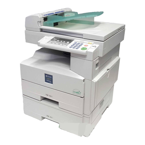
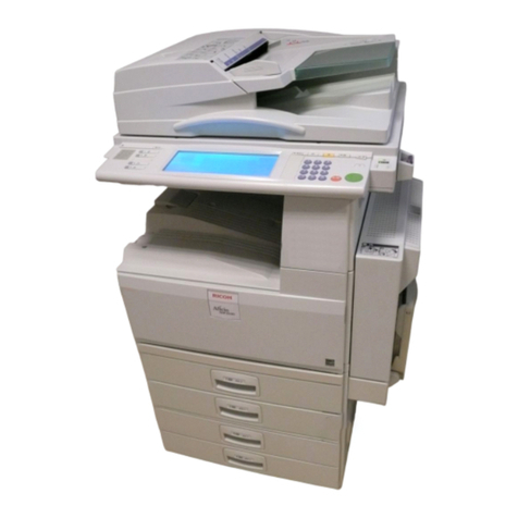
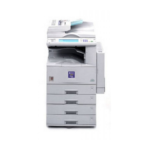
Ricoh MT-C1 User manual

MODEL MT-C1
(Machine Code: B064/B065
MODEL MT-C2
B140/B141/B163/B142/B143/B228
MODEL MT-C3
B246/B248/B249/B250/B252/B253
SERVICE MANUAL
15 February 2006
Subject to Change

!IMPORTANT SAFETY NOTICES
PREVENTION OF PHYSICAL INJURY
1. Before disassembling or assembling parts of the copier and peripherals,
make sure that the copier power cord is unplugged.
2. The wall outlet should be near the copier and easily accessible.
3. Note that some components of the copier and the paper tray unit are
supplied with electrical voltage even if the main power switch is turned off.
4. If any adjustment or operation check has to be made with exterior covers off
or open while the main switch is turned on, keep hands away from electrified
or mechanically driven components.
5. If the Start key is pressed before the copier completes the warm-up period
(the Start key starts blinking red and green alternatively), keep hands away
from the mechanical and the electrical components as the copier starts
making copies as soon as the warm-up period is completed.
6. The inside and the metal parts of the fusing unit become extremely hot while
the copier is operating. Be careful to avoid touching those components with
your bare hands.
HEALTH SAFETY CONDITIONS
1. Never operate the copier without the ozone filters installed.
2. Always replace the ozone filters with the specified ones at the specified
intervals.
3. Toner and developer are non-toxic, but if you get either of them in your eyes
by accident, it may cause temporary eye discomfort. Try to remove with eye
drops or flush with water as first aid. If unsuccessful, get medical attention.
OBSERVANCE OF ELECTRICAL SAFETY STANDARDS
1. The copier and its peripherals must be installed and maintained by a
customer service representative who has completed the training course on
those models.
2. The NVRAM on the system control board has a lithium battery which can
explode if replaced incorrectly. Replace the NVRAM only with an identical
one. The manufacturer recommends replacing the entire NVRAM. Do not
recharge or burn this battery. Used NVRAM must be handled in accordance
with local regulations.

SAFETY AND ECOLOGICAL NOTES FOR DISPOSAL
1. Do not incinerate toner bottles or used toner. Toner dust may ignite suddenly
when exposed to an open flame.
2. Dispose of used toner, developer, and organic photoconductors in
accordance with local regulations. (These are non-toxic supplies.)
3. Dispose of replaced parts in accordance with local regulations.
4. When keeping used lithium batteries in order to dispose of them later, do not
put more than 100 batteries per sealed box. Storing larger numbers or not
sealing them apart may lead to chemical reactions and heat build-up.
LASER SAFETY
The Center for Devices and Radiological Health (CDRH) prohibits the repair of
laser-based optical units in the field. The optical housing unit can only be repaired
in a factory or at a location with the requisite equipment. The laser subsystem is
replaceable in the field by a qualified Customer Engineer. The laser chassis is not
repairable in the field. Customer engineers are therefore directed to return all
chassis and laser subsystems to the factory or service depot when replacement of
the optical subsystem is required.
!WARNING
Use of controls, or adjustment, or performance of procedures other than
those specified in this manual may result in hazardous radiation exposure.
!WARNING
WARNING: Turn off the main switch before attempting any of the
procedures in the Laser Unit section. Laser beams can
seriously damage your eyes.
CAUTION MARKING:

What This Manual Contains
This preliminary manual describes the installation procedures for the
B064/B065/B246 Series Copiers and their peripheral devices:
Conventions in this Manual
This manual describes more than one machine.
The following short notations are used in text to refer to the following machines.
Short Notations What They Mean
B064 Series B064/B065
B140 Series B140/B141/B142/B143/B163/B228
B246 Series B246/B248/B249/B250/B252/B253
This manual uses several symbols.
Symbol What it means
☛Refer to section number
!See Core Tech Manual for
details
"Screw
#Connector
$E-ring
%Clip ring
&' Clamp
Long Edge Feed (LEF)Short Edge Feed (SEF)

i
TABLE OF CONTENTS
1. INSTALLATION .......................................................................... 1-1
1.1 INSTALLATION REQUIREMENTS ...........................................................1-1
1.1.1 OPERATING ENVIRONMENT .........................................................1-1
1.1.2 MACHINE LEVEL.............................................................................1-2
1.1.3 MINIMUM SPACE REQUIREMENTS...............................................1-3
1.1.4 DIMENSIONS ...................................................................................1-4
B064 Series ..........................................................................................1-4
B140 Series ..........................................................................................1-5
B246 Series ..........................................................................................1-6
1.1.5 PERIPHERAL/OPTION SUMMARY TABLE.....................................1-7
1.1.6 POWER REQUIREMENTS ............................................................1-10
1.2 MAIN MACHINE (B064 SERIES/B140 SERIES/B246 SERIES) .............1-11
1.2.1 ACCESSORY CHECK....................................................................1-11
1.2.2 INSTALLATION PROCEDURE ......................................................1-12
Removing Tapes and Retainers .........................................................1-12
Connecting the ADF............................................................................1-14
Removing and Filling the Development Unit .......................................1-15
Re-installing the Development Unit.....................................................1-17
Initializing the Drum Settings (B064 Series)........................................1-18
Initializing the Drum Settings (B140/B246 Series) ..............................1-19
Tandem Tray ......................................................................................1-20
Machine Level.....................................................................................1-22
Date/Time Setting ...............................................................................1-22
SP Codes............................................................................................1-22
1.3 A3/DLT FEEDER KIT (B475)...................................................................1-23
1.3.1 ACCESSORY CHECK....................................................................1-23
INSTALLATION PROCEDURE ..........................................................1-24
1.4 LCT (B473)..............................................................................................1-26
1.4.1 ACCESSORY CHECK....................................................................1-26
1.4.2 INSTALLATION PROCEDURE ......................................................1-27
Removing Tape ..................................................................................1-27
Preparing the Main Machine ...............................................................1-28
Installing the LCT ................................................................................1-28
1.5 LG/B4 FEEDER KIT (B474).....................................................................1-30
1.5.1 ACCESSORY CHECK....................................................................1-30
1.5.2 INSTALLATION PROCEDURE ......................................................1-31
1.6 3000-SHEET FINISHERS (B468/B469/B674).........................................1-34
1.6.1 ACCESSORY CHECK....................................................................1-34
1.6.2 INSTALLATION PROCEDURE ......................................................1-35
Removing Tapes and Retainers .........................................................1-35
Installation...........................................................................................1-37
Selecting the Staple Supply Name .....................................................1-40
Enabling Booklet Binding....................................................................1-40
1.7 PUNCH UNIT (B377)...............................................................................1-41
1.7.1 ACCESSORY CHECK....................................................................1-41

ii
1.7.2 INSTALLATION PROCEDURE ......................................................1-42
1.8 COVER INTERPOSER TRAY (B470) .....................................................1-44
1.8.1 ACCESSORY CHECK....................................................................1-44
1.8.2 INSTALLATION PROCEDURE ......................................................1-45
Removing Tapes and Retainers .........................................................1-45
Attaching the Extensions ....................................................................1-46
Attaching the Interposer Tray..............................................................1-47
Attaching the Corner Plates for the B478/B706 ..................................1-48
Right Rear Corner Plate (B478/B706 only) .........................................1-48
Right Front Corner Plate (B478/B706 only) ........................................1-49
Attaching the Finisher to the Machine.................................................1-50
1.9 9-BIN MAILBOX (B471)...........................................................................1-52
1.9.1 ACCESSORY CHECK....................................................................1-52
1.9.2 INSTALLATION PROCEDURE ......................................................1-53
Removing Tapes and Retainers .........................................................1-53
Installation...........................................................................................1-53
1.10 3000 SHEET FINISHER (B478/B706)...................................................1-55
1.10.1 ACCESSORY CHECK..................................................................1-55
1.10.2 INSTALLATION ............................................................................1-56
1.10.3 MOVING THE FINISHER TO A NEW LOCATION .......................1-58
1.11 PUNCH UNIT (B531/B812) ...................................................................1-59
1.11.1 ACCESSORY CHECK..................................................................1-59
1.11.2 INSTALLATION ............................................................................1-60
1.12 JOGGER UNIT (B513) ..........................................................................1-64
1.12.1 ACCESSORY CHECK..................................................................1-64
1.12.2 INSTALLATION PROCEDURE ....................................................1-65
1.13 Z-FOLDING UNIT (B660) ......................................................................1-66
1.13.1 ACCESSORY CHECK..................................................................1-66
1.13.2 INSTALLATION PROCEDURE ....................................................1-67
Before You Begin................................................................................1-67
Unpacking...........................................................................................1-68
Docking to the Finisher .......................................................................1-69
Docking to the Main Frame.................................................................1-72
1.14 2000/3000 SHEET FINISHERS (B700/B701)........................................1-74
1.14.1 ACCESSORIES............................................................................1-74
1.14.2 INSTALLATION PROCEDURE ....................................................1-75
Removing Tapes and Retainers .........................................................1-75
Docking the Finisher ...........................................................................1-78
Attaching the Trays.............................................................................1-81
Leveling the Finisher...........................................................................1-82
Selecting the Staple Supply Name .....................................................1-83
Enabling Booklet Binding (B700 Only)................................................1-83
Auxiliary Trays ....................................................................................1-84
1.15 PUNCH UNIT (B702).............................................................................1-86
1.15.1 ACCESSORIES............................................................................1-86
1.15.2 INSTALLATION PROCEDURE ....................................................1-87
1.16 COVER INTERPOSER TRAY (B704) ...................................................1-90
1.16.1 ACCESSORIES............................................................................1-90
1.16.2 INSTALLATION PROCEDURE ....................................................1-91

iii
Removing Tapes and Retainers .........................................................1-91
Preparing the Finisher (B700/B701/B706) ..........................................1-92
Attaching the Extensions for the B706................................................1-93
Prepare the Cover Interposer for the B706 .........................................1-94
Attach the Extensions to the B706......................................................1-95
Attaching the Extensions for the B700/B701.......................................1-96
Attaching the Interposer Tray (B700/B701/ B706) ..............................1-97
Attaching the Corner Plates for the B706............................................1-98
Docking the Finisher and Interposer to the Machine (B700/B701/B706).....1-100
1.17 OUTPUT JOGGER UNIT (B703).........................................................1-102
1.17.1 ACCESSORIES..........................................................................1-102
1.17.2 INSTALLATION PROCEDURE ..................................................1-103
1.18 MAIL BOX (B762)................................................................................1-105
1.18.1 ACCESSORY CHECK................................................................1-105
1.18.2 INSTALLATION PROCEDURE ..................................................1-106
1.19 COPY TRAY (B756) ............................................................................1-109
1.19.1 ACCESSORIES..........................................................................1-109
1.19.2 INSTALLATION ..........................................................................1-110
1.20 KEY CARD BRACKET (B498), KEY COUNTER BRACKET (B452) ...1-113
1.20.1 KEY CARD BRACKET B498 ACCESSORIES ...........................1-113
1.20.2 KEY COUNTER BRACKET B452 ACCESSORIES....................1-114
1.20.3 INSTALLATION ..........................................................................1-115
Assemble the Key Counter Bracket ..................................................1-115
Install the Key Card Bracket and Assembled Key Counter ...............1-116
1.21 COPY CONNECTOR KITS .................................................................1-118
1.21.1 COPY CONNECTOR KIT (B525-10, -12) FOR B064 SERIES...1-118
ACCESSORY CHECK......................................................................1-119
Installation.........................................................................................1-120
Installing the Hardware .....................................................................1-121
1.21.2 COPY CONNECTOR KIT (B328-03) FOR B140 SERIES ..........1-125
ACCESSORY CHECK......................................................................1-125
Preparation .......................................................................................1-126
Installation.........................................................................................1-127
1.21.3 COPY CONNECTOR (B842) FOR B246 SERIES......................1-130
Accessories ......................................................................................1-130
Preparation .......................................................................................1-131
Installation.........................................................................................1-132
1.22 MFP OPTIONS: B064 SERIES ...........................................................1-135
1.22.1 PRINTER/SCANNER KIT (G338), PRINTER KIT (G339) ..........1-135
ACCESSORY CHECK......................................................................1-135
1.22.2 INSTALLATION PROCEDURE ..................................................1-136
Inserting DIMMs................................................................................1-136
Installation Procedure .......................................................................1-137
1.22.3 PS3 (B525-08)............................................................................1-139
1.22.4 USB 2.0 (B525-01) .....................................................................1-140
ACCESSORY CHECK......................................................................1-140
Installation Procedure .......................................................................1-140
USB SP Settings...............................................................................1-141
1.22.5 IEEE1394 (G561) FIREWIRE INTERFACE................................1-142
i
v
ACCESSORY CHECK......................................................................1-142

Installation Procedure .......................................................................1-143
UP Mode Settings for IEEE 1394......................................................1-144
SP Mode Settings for IEEE 1394......................................................1-145
1.22.6 IEEE802.11B WIRELESS LAN (G628).......................................1-146
ACCESSORY CHECK......................................................................1-146
Installation Procedure .......................................................................1-147
UP Mode Settings for Wireless LAN .................................................1-148
SP MODE SETTINGS FOR 802.11B WIRELESS LAN................................1-150
1.22.7 FILE FORMAT CONVERTER (MLB) (B519) ..............................1-151
ACCESSORY CHECK......................................................................1-152
Installation Procedure .......................................................................1-152
Installing the Firmware......................................................................1-152
Installing the Hardware .....................................................................1-153
1.23 MFP OPTIONS: B140 SERIES ...........................................................1-154
1.23.1 MERGING APPLICATIONS ON ONE SD CARD .......................1-154
Overview...........................................................................................1-154
Merging Applications.........................................................................1-155
Undo Exec ........................................................................................1-156
Storing Copied SD Cards On Site.....................................................1-157
1.23.2 OVERVIEW ................................................................................1-158
1.23.3 PRINTER/SCANNER KIT (B659) ...............................................1-159
ACCESSORY CHECK......................................................................1-159
Installation.........................................................................................1-160
1.23.4 PS3 (B525-15)............................................................................1-163
ACCESSORY CHECK......................................................................1-163
Installation.........................................................................................1-163
1.23.5 USB 2.0 INTERFACE BOARD (B596-01) ..................................1-164
ACCESSORY CHECK......................................................................1-164
Installation.........................................................................................1-164
1.23.6 IEEE 1394 INTERFACE BOARD (B581-01)...............................1-165
ACCESSORY CHECK......................................................................1-165
Installation.........................................................................................1-165
1.23.7 IEEE 802.11B INTERFACE BOARD (B582-01, -02) ..................1-166
ACCESSORY CHECK......................................................................1-166
Installation.........................................................................................1-166
1.23.8 BLUETOOTH INTERFACE UNIT (G377) ...................................1-168
ACCESSORY CHECK......................................................................1-168
Installation.........................................................................................1-168
1.23.9 FILE FORMAT CONVERTER (B609).........................................1-169
ACCESSORY CHECK......................................................................1-169
Installation.........................................................................................1-169
1.23.10 DATA OVERWRITE SECURITY UNIT (B735) .........................1-170
ACCESSORY CHECK......................................................................1-170
Before You Begin… ..........................................................................1-170
Seal Check And Removal .................................................................1-171
Installation Procedure .......................................................................1-172
1.24 MFP OPTIONS: B246 SERIES ...........................................................1-175
1.24.1 OVERVIEW ................................................................................1-175

v
1.24.2 COMMON PROCEDURES.........................................................1-176
Inserting SD Cards............................................................................1-176
Storing Copied SD Cards..................................................................1-176
1.24.3 PRINTER SCANNER KIT (B841) ...............................................1-177
ACCESSORY CHECK......................................................................1-177
Installation.........................................................................................1-178
1.24.4 POSTSCRIPT3 (B525)...............................................................1-181
Accessories ......................................................................................1-181
Installation.........................................................................................1-181
1.24.5 IEEE1394 INTERFACE BOARD (B581).....................................1-182
Accessories ......................................................................................1-182
Installation.........................................................................................1-182
1.24.6 WIRELESS LAN G813 (802.11B)...............................................1-183
Accessories ......................................................................................1-183
Installation.........................................................................................1-183
1.24.7 BLUETOOTH INTERFACE UNIT TYPE C B826........................1-184
Accessories ......................................................................................1-184
Installation.........................................................................................1-184
1.24.8 FILE FORMAT CONVERTER TYPE C B609 .............................1-185
ACCESSORY CHECK......................................................................1-185
Installation.........................................................................................1-185
1.24.9 DATA OVERWRITE SECURITY UNIT TYPE C B735................1-186
ACCESSORY CHECK......................................................................1-186
Before You Begin… ..........................................................................1-186
Seal Check And Removal .................................................................1-187
Installation Procedure .......................................................................1-188
1.24.10 REMOTE COMMUNICATION GATE TYPE CM1 (B818).........1-191
Accessories ......................................................................................1-191
Installation.........................................................................................1-191
1.24.11 USB HOST INTERFACE UNIT TYPE A (B825) .......................1-194
Accessory Check ..............................................................................1-194
Installation.........................................................................................1-194
1.24.12 BROWSER UNIT TYPE B (B828) ............................................1-195
Accessories ......................................................................................1-195
Installation.........................................................................................1-195
1.24.13 COPY DATA SECURITY UNIT TYPE C (B829).......................1-196
Accessories ......................................................................................1-196
Installation.........................................................................................1-196
B246 Series: IPU ..............................................................................1-196
1.24.14 VM CARD (B861) .....................................................................1-198
Accessories ......................................................................................1-198
Installation.........................................................................................1-198
1.24.15 IEEE1284 B679 ........................................................................1-199
Accessories ......................................................................................1-199
Installation.........................................................................................1-199
1.24.16 GIGABIT ETHERNET G381 .....................................................1-200
Accessories ......................................................................................1-200
Installation.........................................................................................1-200

vi
2. PREVENTIVE MAINTENANCE................................................... 2-1
2.1 PM TABLES ..............................................................................................2-1
2.1.1 MAIN MACHINE ...............................................................................2-1
2.1.2 ADF ..................................................................................................2-5
2.1.3 OPTIONAL PERIPHERAL DEVICES ...............................................2-5
LCT (Large Capacity Tray) B473 ..........................................................2-5
Cover Interposer Tray B470..................................................................2-5
3000-Sheet Finisher with 50-sheet stapler and Saddle-Stitching
B468/B469/B674...................................................................................2-6
3000-Sheet Finisher B478/B706...........................................................2-6
Z-Folding Unit Type 2105 (B660)..........................................................2-6
2000/3000-Sheet Booklet Finisher B700/B701.....................................2-7
Punch B702 ..........................................................................................2-7
2.2 RELATED SP CODES ..............................................................................2-7
3. REPLACEMENT AND ADJUSTMENT........................................ 3-1
3.1 GENERAL CAUTIONS..............................................................................3-1
3.1.1 DRUM...............................................................................................3-1
3.1.2 DRUM UNIT .....................................................................................3-1
3.1.3 TRANSFER BELT UNIT ...................................................................3-2
3.1.4 SCANNER UNIT...............................................................................3-2
3.1.5 LASER UNIT ....................................................................................3-2
3.1.6 CHARGE CORONA..........................................................................3-3
3.1.7 DEVELOPMENT...............................................................................3-3
3.1.8 CLEANING .......................................................................................3-4
3.1.9 FUSING UNIT...................................................................................3-4
3.1.10 PAPER FEED.................................................................................3-4
3.1.11 USED TONER ................................................................................3-4
3.2 SPECIAL TOOLS AND LUBRICANTS ................................................3-5
3.2.1 SPECIAL TOOLS .............................................................................3-5
3.2.2 LUBRICANTS...................................................................................3-5
3.3 OPERATION PANEL AND EXTERNAL COVERS ....................................3-6
3.3.1 OPERATION PANEL........................................................................3-6
3.3.2 FRONT DOOR..................................................................................3-6
3.3.3 RIGHT COVERS ..............................................................................3-7
3.3.4 LEFT COVERS.................................................................................3-8
3.3.5 REAR COVERS................................................................................3-9
3.4 SCANNER...............................................................................................3-10
3.4.1 ADF AND TOP COVERS ...............................................................3-10
ADF.....................................................................................................3-10
Top Covers .........................................................................................3-11
3.4.2 EXPOSURE GLASS.......................................................................3-12
3.4.3 SCANNER ORIGINAL SIZE SENSORS.........................................3-13
3.4.4 LENS BLOCK .................................................................................3-14
3.4.5 EXPOSURE LAMP .........................................................................3-15
3.4.6 LAMP REGULATOR.......................................................................3-16
3.4.7 SCANNER MOTOR DRIVE BOARD (SDRB).................................3-17
3.4.8 SCANNER MOTOR........................................................................3-18

vii
3.4.9 SCANNER HP SENSOR ................................................................3-19
3.4.10 SCANNER WIRE REPLACEMENT ..............................................3-20
Preparation for Removal .....................................................................3-20
Wire Removal: Back ...........................................................................3-21
Wire Removal: Front...........................................................................3-22
Attaching the New Wire ......................................................................3-23
3.4.11 SCANNER HEATER.....................................................................3-25
3.5 LASER UNIT ...........................................................................................3-26
3.5.1 CAUTION DECALS ........................................................................3-26
3.5.2 LD UNIT AND POLYGON MOTOR ................................................3-27
3.5.3 LASER SYNCHRONIZATION DETECTOR REPLACEMENT........3-29
3.5.4 LASER UNIT ALIGNMENT.............................................................3-30
3.6 DRUM UNIT ............................................................................................3-32
3.6.1 DEVELOPMENT UNIT REMOVAL.................................................3-32
Removal..............................................................................................3-32
Re-installation .....................................................................................3-33
Replacement with a used Development Unit ......................................3-33
3.6.2 CHARGE CORONA UNIT ..............................................................3-34
3.6.3 CHARGE CORONA WIRE AND GRID...........................................3-35
3.6.4 CHARGE CORONA WIRE CLEANING PADS ...............................3-36
3.6.5 OPC DRUM REMOVAL..................................................................3-37
Dusting the Drum Surface...................................................................3-38
3.6.6 PTL (B140 SERIES ONLY) ............................................................3-39
3.6.7 QUENCHING LAMP.......................................................................3-40
3.6.8 DRUM POTENTIAL SENSOR........................................................3-40
3.6.9 CLEANING FILTER ........................................................................3-41
3.6.10 CLEANING BLADE.......................................................................3-41
3.6.11 CLEANING BRUSH......................................................................3-42
3.6.12 PICK-OFF PAWLS .......................................................................3-43
3.6.13 ID SENSOR..................................................................................3-43
3.6.14 DRUM MOTOR.............................................................................3-44
3.6.15 TONER COLLECTION BOTTLE ..................................................3-45
3.6.16 TONER SEPARATION UNIT........................................................3-45
3.6.17 OZONE FILTERS .........................................................................3-46
3.6.18 OPTICS DUST FILTER ................................................................3-46
3.6.19 INTERNAL DUST FILTER............................................................3-46
3.7 DEVELOPMENT UNIT ............................................................................3-47
3.7.1 DEVELOPER REPLACEMENT......................................................3-47
3.7.2 DEVELOPMENT FILTER ...............................................................3-49
3.7.3 ENTRANCE SEAL AND SIDE SEALS ...........................................3-50
3.7.4 TD SENSOR...................................................................................3-51
3.7.5 TONER END SENSOR ..................................................................3-51
3.7.6 TONER SUPPLY MOTOR..............................................................3-52
3.7.7 DEVELOPMENT MOTOR ..............................................................3-53
3.8 TRANSFER BELT UNIT..........................................................................3-54
3.8.1 TRANSFER BELT UNIT .................................................................3-54
3.8.2 TRANSFER BELT ..........................................................................3-55
3.8.3 TRANSFER ROLLER CLEANING BLADE .....................................3-57
3.8.4 DISCHARGE PLATE......................................................................3-58

viii
3.8.5 TRANSFER POWER PACK ...........................................................3-59
3.9 FUSING UNIT..........................................................................................3-60
3.9.1 FUSING UNIT.................................................................................3-60
3.9.2 FUSING PRESSURE RELEASE MOTOR (B140 SERIES)............3-62
3.9.3 FUSING PRESSURE RELEASE HP SENSOR (B140 SERIES) ....3-63
3.9.4 FUSING UNIT THERMISTORS AND THERMOSTATS .................3-64
B064 Series ........................................................................................3-65
B140 Series ........................................................................................3-65
B246 Series ........................................................................................3-65
3.9.5 WEB CLEANING ROLLER.............................................................3-68
Web Unit Disassembly........................................................................3-68
Web Unit Assembly.............................................................................3-69
3.9.6 WEB MOTOR AND WEB END SENSOR.......................................3-70
3.9.7 PRESSURE ROLLER CLEANING UNIT ........................................3-71
B064 Series ........................................................................................3-71
B140 Series ........................................................................................3-72
3.9.8 FUSING LAMPS, HOT ROLLER, AND PRESSURE ROLLER.......3-73
B064 Series: Fusing Lamps................................................................3-73
B140 Series: Fusing Lamps................................................................3-74
Important Notes about Fusing Unit Assembly (B064 Series)..............3-79
3.9.9 PRESSURE ROLLER.....................................................................3-80
3.9.10 STRIPPER PAWLS ......................................................................3-81
B064 Series ........................................................................................3-81
B140 Series ........................................................................................3-82
3.9.11 NIP BAND WIDTH ADJUSTMENT...............................................3-83
3.9.12 FUSING UNIT EXIT SENSOR......................................................3-84
3.9.13 FUSING/EXIT MOTOR.................................................................3-85
3.9.14 FUSING EXIT AND EXIT UNIT ENTRANCE SENSORS .............3-86
3.10 DUPLEX UNIT.......................................................................................3-87
3.10.1 DUPLEX UNIT REMOVAL ...........................................................3-87
3.10.2 DUPLEX UNIT SIDE-TO-SIDE ADJUSTMENT............................3-88
3.10.3 JOGGER FENCE ADJUSTMENT ................................................3-88
3.10.4 DUPLEX MOTORS.......................................................................3-89
Duplex Inverter Motor .........................................................................3-89
Duplex Jogger and Transport Motors..................................................3-90
3.10.5 DUPLEX TRANSPORT CLUTCH/JOGGER HP SENSOR...........3-91
3.10.6 DUPLEX ENTRANCE SENSOR...................................................3-92
3.10.7 DUPLEX TRANSPORT SENSOR 3 .............................................3-93
3.10.8 INVERTER EXIT SENSOR, TRANSPORT SENSORS 1 & 2.......3-94
3.10.9 DUPLEX JOGGER BELT ADJUSTMENT ....................................3-95
3.11 PAPER FEED........................................................................................3-96
3.11.1 PAPER TRAY REMOVAL ............................................................3-96
3.11.2 REAR FENCE RETURN SENSOR REPLACEMENT...................3-98
3.11.3 REAR FENCE HP SENSOR REPLACEMENT.............................3-99
3.11.4 TANDEM RIGHT TRAY PAPER SENSOR REPLACEMENT.....3-100
3.11.5 BOTTOM PLATE LIFT WIRE REPLACEMENT..........................3-101
3.11.6 TANDEM TRAY PAPER SIZE CHANGE....................................3-103
3.11.7 PICK-UP, FEED, SEPARATION ROLLER REPLACEMENT .....3-106
3.11.8 FEED UNIT.................................................................................3-107

ix
3.11.9 SEPARATION ROLLER PRESSURE ADJUSTMENT................3-109
3.11.10 RELAY SENSOR......................................................................3-110
3.11.11 BY-PASS PAPER SIZE DETECTION BOARD.........................3-111
3.11.12 BY-PASS TRAY ROLLERS......................................................3-112
3.11.13 BY-PASS SEPARATION ROLLER PRESSURE ADJUSTMENT .3-113
3.11.14 REGISTRATION SENSOR.......................................................3-114
3.11.15 REGISTRATION AND BY-PASS UNIT REMOVAL..................3-115
3.12 PCBS AND HDD .................................................................................3-117
3.12.1 BCU BOARD (BASE ENGINE CONTROL UNIT).......................3-117
BCU: B064, B140 Series ..................................................................3-117
BCU, IOB: B246 Series.....................................................................3-118
3.12.2 CONTROLLER BOARD .............................................................3-119
B064 Series: Controller Board ..........................................................3-119
B140 Series: Controller Board ..........................................................3-120
B246 Series: Controller Board ..........................................................3-121
3.12.3 IPU BOARD................................................................................3-122
B064 Series: IPU Board....................................................................3-122
B140 Series: IPU, Mother Board.......................................................3-123
B246 Series: IPU ..............................................................................3-126
B246 Series Motherboard .................................................................3-127
3.12.4 DEVELOPMENT POWER PACK ...............................................3-129
3.12.5 PSU, PFC BOARDS...................................................................3-130
B064 Series ......................................................................................3-130
B140 Series PSU..............................................................................3-130
B246 Series PSU..............................................................................3-131
3.12.6 HDD............................................................................................3-132
B064 Series HDD..............................................................................3-132
B140 Series HDD..............................................................................3-133
B246 Series HDD..............................................................................3-134
3.12.7 NVRAM.......................................................................................3-135
NVRAM: B064 Series, B140 Series..................................................3-135
NVRAM: B246 Series .......................................................................3-137
3.12.8 DIMMS........................................................................................3-139
3.13 ADF .....................................................................................................3-140
3.13.1 ADF COVERS ............................................................................3-140
3.13.2 FEED UNIT.................................................................................3-141
3.13.3 FEED BELT AND PICK-UP ROLLER.........................................3-142

3.13.4 SEPARATION ROLLER .............................................................3-143
3.13.5 REGISTRATION SENSOR.........................................................3-144
3.13.6 ADF CONTROL BOARD ............................................................3-145
3.13.7 ORIGINAL WIDTH, INTERVAL, AND SKEW
CORRECTION SENSORS ......................................................3-146
3.13.8 ORIGINAL LENGTH SENSORS.................................................3-147
3.13.9 DF POSITION AND APS SENSOR ............................................3-148
3.13.10 OTHER ADF SENSORS ..........................................................3-149
3.13.11 BOTTOM PLATE LIFT MOTOR ...............................................3-150
3.13.12 FEED MOTOR..........................................................................3-150
3.13.13 EXIT MOTOR AND TRANSPORT MOTOR .............................3-151
3.13.14 PICK-UP ROLLER MOTOR AND HP SENSOR.......................3-152

x
3.13.15 CIS POWER SUPPLY BOARD AND CIS UNIT........................3-153
3.13.16 ADF EXIT SENSOR .................................................................3-154
3.14 COPY IMAGE ADJUSTMENTS: PRINTING/SCANNING ...................3-155
3.14.1 PRINTING ..................................................................................3-155
Registration - Leading Edge/Side-to-Side.........................................3-155
Blank Margin.....................................................................................3-156
Registration Buckle Adjustment ........................................................3-156
3.14.2 SCANNING.................................................................................3-157
Registration: Platen Mode.................................................................3-157
Magnification.....................................................................................3-157
3.14.3 ADF SCANNING ADJUSTMENTS .............................................3-158
Vertical Black Lines...........................................................................3-158
DIP Switch Settings (ADF Main Board).............................................3-158
ADF Skew Correction .......................................................................3-158
3.15 TOUCH SCREEN CALIBRATION.......................................................3-160
4. TROUBLESHOOTING ................................................................ 4-1
4.1 OVERVIEW ...............................................................................................4-1
4.1.1 RECOVERY METHODS...................................................................4-2
4.1.2 IMPORTANT SP CODES .................................................................4-2
4.1.3 DOWNLOAD ERROR CODES.........................................................4-3
4.1.4 JAM DETECTION.............................................................................4-6
SENSOR LOCATIONS .........................................................................4-6
4.1.5 TIMING CHARTS .............................................................................4-7
Feed, Transport, Feed Out: Face-up ....................................................4-7
Transport, Inverter, Feed Out: Face-down............................................4-8
Duplex Transport ..................................................................................4-9
4.1.6 PROGRAM DOWNLOAD ...............................................................4-10
4.2 B064 SERIES SERVICE MODE..............................................................4-11
4.2.1 B064 SERIES SERVICE CALL CONDITIONS ...............................4-11
4.2.2 B064 SERIES SC CODE DESCRIPTIONS ....................................4-12
SC100: Scanning System ...................................................................4-12
SC300: Image Development System (1).............................................4-15
SC400: Image Development System (2).............................................4-20
SC500: Feed, Transport, Duplexing, and Fusing Systems .................4-21
SC600: Data Communication .............................................................4-24
SC700: Peripherals.............................................................................4-26
SC800: Overall System.......................................................................4-29
SC900: Miscellaneous ........................................................................4-32
4.2.3 ADDITIONAL SC CODES PRINTED IN SMC REPORT ................4-34
4.3 B140/B246 SERIES SERVICE MODE ....................................................4-37
4.3.1 SERVICE MODE LOCK/UNLOCK..................................................4-37
4.3.2 B140/B246 SERIES SERVICE CALL CONDITIONS......................4-38
4.3.3 B140/B246 SERIES SC CODE DESCRIPTIONS...........................4-39
SC100: Scanning System ...................................................................4-40
SC200: Exposure................................................................................4-43
SC300: Image Development System (1).............................................4-44
SC400: Image Development System (2).............................................4-49
SC500: Feed, Transport, Duplexing, and Fusing Systems .................4-50

xi
SC600: Data Communication .............................................................4-55
SC700: Peripherals.............................................................................4-57
SC800: Overall System.......................................................................4-66
SC900: Miscellaneous ........................................................................4-72
4.3.4 JAM CODES...................................................................................4-76
Main Unit: Paper Jam Errors...............................................................4-76
Finisher B469 Jam Codes...................................................................4-77
Finisher B468/B674 Jam Codes .........................................................4-77
Finisher B478/B706 Jam Codes .........................................................4-78
Mailbox B471 Jam Codes ...................................................................4-78
Cover Interposer Tray B470 Jam Codes.............................................4-78
Z-Folding Unit B660 Jam Codes.........................................................4-79
4.3.5 ADDITIONAL SC CODES PRINTED IN SMC REPORT ................4-80
4.4 OTHER PROBLEMS (B064/B140/B246 SERIES)...................................4-83
4.4.1 BLOWN FUSE CONDITIONS ........................................................4-83
4.4.2 COMMON PROBLEMS ..................................................................4-83
4.4.3 FREQUENT PAPER JAMS ............................................................4-84
5. SERVICE TABLES...................................................................... 5-1
5.1 SERVICE PROGRAM MODE....................................................................5-1
5.1.1 SERVICE PROGRAM MODE OPERATION.....................................5-1
Service Mode Lock/Unlock ...................................................................5-1
To Enter and Exit the Service Mode .....................................................5-2
To Enter and Exit the Super SP Mode..................................................5-2
To Switch to the Copy Window for Test Printing...................................5-2
Using the SP Mode...............................................................................5-3
SP Mode Button Summary ...................................................................5-4
SP Mode Print (SMC Print) ...................................................................5-5
5.2 RESETS ....................................................................................................5-6
5.2.1 MEMORY ALL CLEAR: SP5801 ......................................................5-6
5.2.2 SOFTWARE AND SETTING RESET .............................................5-10
Software Reset ...................................................................................5-10
Resetting the System..........................................................................5-10
Resetting Copy/Document Server Features Only ...............................5-10
Resetting Scanner Features Only.......................................................5-10
5.3 TEST PATTERN PRINTING....................................................................5-11
5.3.1 PRINTING TEST PATTERN: SP2902-003.....................................5-11
Test Pattern Table ..............................................................................5-12
5.3.2 IPU FRONT/BACK TEST PATTERNS: SP2902-001,002...............5-13
Test Pattern Table ..............................................................................5-14
5.3.3 IPU PRINTING TEST PATTERN: SP2902-004..............................5-15
5.4 SOFTWARE UPDATE.............................................................................5-16
5.4.1 SOFTWARE UPDATE PROCEDURE: B140/B246 SERIES ..........5-16
Updating the LCDC for the Operation Panel.......................................5-21
Downloading Stamp Data ...................................................................5-21
NVRAM Data Upload/Download .........................................................5-22
5.4.2 SOFTWARE UPDATE PROCEDURE: B064 SERIES....................5-23
GW Controller/BCU Update ................................................................5-24
Forced Update ....................................................................................5-25

xii
Stamp Data Update ............................................................................5-25
Operation Panel Software Update ......................................................5-26
Scanner Update..................................................................................5-27
NIB Update .........................................................................................5-27
NetFile Firmware Update ....................................................................5-27
NVRAM Update ..................................................................................5-28
Firmware Update Notes ......................................................................5-28
5.5 SERVICE PROGRAM MODE TABLES...................................................5-29
5.5.1 SERVICE TABLE KEY ...................................................................5-29
5.5.2 COPIER SERVICE TABLE.............................................................5-30
SP1xxx Feed ......................................................................................5-30
SP2xxx Drum......................................................................................5-35
SP3xxx Processing.............................................................................5-53
SP4xxx Scanner .................................................................................5-56
SP5xxx Mode......................................................................................5-67
SP6xxx Peripherals...........................................................................5-119
SP7xxx Data Logs ............................................................................5-130
SP8xxx: Data Log2 ...........................................................................5-147
5.5.3 PRINTER SERVICE TABLE.........................................................5-176
5.5.4 SCANNER SERVICE TABLE .......................................................5-177
5.6 INPUT/OUTPUT CHECK.......................................................................5-189
5.6.1 COPIER INPUT CHECK: SP5803................................................5-189
5.6.2 COPIER OUTPUT CHECK: SP5804 ............................................5-195
5.6.3 ADF INPUT CHECK: SP6007 ......................................................5-197
5.6.4 ADF OUTPUT CHECK: SP6008...................................................5-198
5.6.5 FINISHER INPUT CHECK: SP6117 (B478/B704).......................5-199
5.6.6 FINISHER OUTPUT CHECK: SP6118 .........................................5-201
5.6.7 FINISHER 1 INPUT CHECK: 6121...............................................5-202
5.6.8 FINISHER 1 OUTPUT CHECK: 6124...........................................5-203
5.6.9 FINISHER 2 INPUT CHECK: 6122...............................................5-204
5.6.10 FINISHER 2 OUTPUT CHECK: 6125.........................................5-205
5.7 USING THE DEBUG LOG (B140/B246)................................................5-206
5.7.1 SWITCHING ON AND SETTING UP SAVE DEBUG LOG ...........5-206
5.7.2 RETRIEVING THE DEBUG LOG FROM THE HDD.....................5-209
5.7.3 RECORDING ERRORS MANUALLY ...........................................5-210
5.7.4 NEW DEBUG LOG CODES .........................................................5-211
SP5857-015 Copy SD Card-to-SD Card: Any Desired Key .............5-211
SP5857-016 Create a File on HDD to Store a Log ..........................5-211
SP5857-017 Create a File on SD Card to Store a Log ....................5-211
5.8 USER TOOLS .......................................................................................5-212
5.8.1 OVERVIEW ..................................................................................5-212
5.8.2 SYSTEM SETTINGS ....................................................................5-213
B064 Series System Settings ...........................................................5-213
B140 Series System Settings ...........................................................5-215
5.8.3 COPIER/DOCUMENT SERVER FEATURES ..............................5-218
5.8.4 INQUIRY.......................................................................................5-222
5.8.5 COUNTER....................................................................................5-222
5.9 DIP SWITCH TABLES...........................................................................5-223
5.9.1 BCU (BASE ENGINE CONTROL UNIT).......................................5-223

xiii
5.9.2 CONTROLLER BOARD ...............................................................5-223
6. DETAILED DESCRIPTIONS ....................................................... 6-1
6.1 OVERVIEW ...............................................................................................6-1
6.1.1 PAPER PATH (WITH COVER INTERPOSER TRAY) ......................6-3
6.1.2 PAPER PATH (WITH 9-BIN MAILBOX) ...........................................6-4
6.1.3 DRIVE LAYOUT ...............................................................................6-5
6.2 BOARD STRUCTURE...............................................................................6-6
6.2.1 BLOCK DIAGRAM............................................................................6-6
6.2.2 COMPONENT DESCRIPTIONS.......................................................6-7
BCU (Base Engine Control Unit)...........................................................6-7
Controller Board....................................................................................6-7
MB (Mother Board) ...............................................................................6-7
IPU (Image Processing Unit) ................................................................6-7
SBU (Sensor Board Unit)......................................................................6-8
PFC (Paper Feed Control) ....................................................................6-8
SDRB (Scanner Driver Board)..............................................................6-8
VIB (Video Interface Board) ..................................................................6-8
DRB (Drive Board)................................................................................6-8
CNB (Connection Board) ......................................................................6-8
HDD (Hard Disk Drive)..........................................................................6-9
6.3 COPY PROCESS OVERVIEW................................................................6-10
6.4 ADF .........................................................................................................6-12
6.4.1 OVERVIEW ....................................................................................6-12
6.4.2 ADF DRIVE LAYOUT .....................................................................6-13
6.4.3 PICK-UP ROLLER LIFT .................................................................6-14
6.4.4 BOTTOM PLATE LIFT....................................................................6-15
6.4.5 ORIGINAL SEPARATION ..............................................................6-16
6.4.6 ORIGINAL TRANSPORT ...............................................................6-17
6.4.7 ORIGINAL SKEW CORRECTION..................................................6-18
6.4.8 ORIGINAL SIZE DETECTION........................................................6-20
6.4.9 ADF SCANNING.............................................................................6-23
6.4.10 JAM DETECTION.........................................................................6-24
6.5 SCANNING..............................................................................................6-25
6.5.1 OVERVIEW ....................................................................................6-25
6.5.2 SCANNER DRIVE ..........................................................................6-26
6.5.3 ORIGINAL SIZE DETECTION........................................................6-27
Sensors...............................................................................................6-27
Detection Timing.................................................................................6-28
6.5.4 SCANNING MAGNIFICATION .......................................................6-29
Book Mode..........................................................................................6-29
6.5.5 AUTO IMAGE DENSITY (ADS)......................................................6-30
Xenon Lamp →CCD ADS..................................................................6-30
CIS ADS .............................................................................................6-30
6.6 IMAGE PROCESSING ............................................................................6-31
6.6.1 OVERVIEW ....................................................................................6-31
6.6.2 IMAGE PROCESSING FLOW ........................................................6-32
6.6.3 IMAGE PROCESSING MODES .....................................................6-33
6.6.4 IMAGE QUALITY SP ADJUSTMENTS...........................................6-34

xi
v
Custom Settings for Each Mode: Image Quality .................................6-34
Custom Settings for Each Mode: Line Width Correction.....................6-36
Custom Setting: Duplex Scanning Mode Original Image Quality Settings.. 6-38
Settings Adjustable for Each Original Mode........................................6-39
6.6.5 RELATION BETWEEN THE SP AND UP SETTINGS....................6-40
6.6.6 IMAGE PROCESSING TROUBLESHOOTING ..............................6-42
Removing Background from Coarse Paper ........................................6-42
Improving the Appearance of a Copy of a Color Document................6-42
Removing Vertical White Lines During Duplex Scanning....................6-43
Equalizing Duplex Scanned Image Quality of Front/Back Sides.........6-44
Equalizing Image Quality of Front Sides for Duplex and Simplex Modes ...6-44
6.7 LASER EXPOSURE................................................................................6-45
6.7.1 OVERVIEW ....................................................................................6-45
6.7.2 OPTICAL PATH..............................................................................6-46
6.7.3 FOUR-BEAM EXPOSURE .............................................................6-47
6.7.4 COOLING FAN...............................................................................6-48
6.7.5 LD SAFETY SWITCHES ................................................................6-49
B064 Series, B140 Series Safety Switches ........................................6-49
B246 Series Safety Switches..............................................................6-50
6.8 DRUM UNIT ............................................................................................6-51
6.8.1 OVERVIEW ....................................................................................6-51
6.8.2 OPC DRUM ....................................................................................6-52
6.8.3 DRUM DRIVE.................................................................................6-52
6.8.4 DRUM CHARGE.............................................................................6-53
6.8.5 CHARGE CORONA WIRE CLEANING..........................................6-54
6.8.6 DRUM PICK-OFF MECHANISM ....................................................6-55
6.8.7 DRUM CLEANING..........................................................................6-56
6.8.8 DRUM VENTILATION AND OZONE FILTER.................................6-57
6.8.9 TONER RECYCLING .....................................................................6-58
6.8.10 WASTE TONER COLLECTION....................................................6-59
Mechanism .........................................................................................6-59
Error Detection....................................................................................6-59
6.8.11 PROCESS CONTROL..................................................................6-60
What Happens at Power On ...............................................................6-60
Drum Potential Sensor Calibration......................................................6-61
Development Bias, Bias Grid, and LD Adjustment..............................6-62
ID Sensor Calibration (Vsg) ................................................................6-64
TD Sensor Calibration (Vref)...............................................................6-64
6.9 DEVELOPMENT AND TONER SUPPLY ................................................6-65
6.9.1 OVERVIEW ....................................................................................6-65
Development Unit ...............................................................................6-65
Toner Supply ......................................................................................6-66
6.9.2 DEVELOPMENT UNIT ...................................................................6-67
6.9.3 DEVELOPER/TONER MIXING (AGITATION)................................6-68
6.9.4 DEVELOPMENT BIAS ...................................................................6-69
6.9.5 TONER SUPPLY............................................................................6-70
6.9.6 DEVELOPMENT UNIT DRIVE AND VENTILATION ......................6-71
6.9.7 TONER END SENSOR ..................................................................6-72
6.9.8 SHUTTER MECHANISM................................................................6-72

x
v
6.9.9 TONER BOTTLE SUPPLY AND VENTILATION ............................6-73
6.9.10 TONER SUPPLY CONTROL .......................................................6-74
Sensor Control Mode..........................................................................6-74
Pixel Count Toner Supply Mode .........................................................6-75
TD Sensor Initialization .......................................................................6-76
Determining Vref .................................................................................6-76
Toner Supply without ID Sensor and TD Sensors ..............................6-77
Abnormal TD Sensor Output...............................................................6-77
Abnormal ID Sensor Output................................................................6-77
Toner End Detection...........................................................................6-78
Toner End Recovery ...........................................................................6-78
6.10 IMAGE TRANSFER AND PAPER SEPARATION.................................6-79
6.10.1 OVERVIEW ..................................................................................6-79
6.10.2 TRANSFER BELT LIFT ................................................................6-80
Mechanism .........................................................................................6-80
Timing .................................................................................................6-81
6.10.3 TRANSFER BELT CHARGE ........................................................6-82
6.10.4 TRANSFER CURRENT SETTINGS.............................................6-83
6.10.5 TRANSFER CURRENT CIRCUIT ................................................6-84
6.10.6 TRANSFER BELT DRIVE AND PAPER TRANSPORT................6-85
6.10.7 TRANSFER BELT CLEANING .....................................................6-86
6.10.8 ANTI-CONDENSATION HEATER................................................6-87
6.11 PAPER FEED........................................................................................6-88
6.11.1 OVERVIEW ..................................................................................6-88
Tray Capacities...................................................................................6-89
Built-in Feed Stations..........................................................................6-89
By-pass Feed......................................................................................6-89
Paper Registration ..............................................................................6-89
Jam Removal......................................................................................6-89
6.11.2 DRIVE...........................................................................................6-90
6.11.3 TRAY AND PAPER LIFT MECHANISM – TRAY 2,3....................6-91
Bottom Plate Lift .................................................................................6-91
Lift Sensor...........................................................................................6-92
6.11.4 PAPER FEED AND SEPARATION MECHANISM........................6-93
Paper Feed and Separation: No Paper Present .................................6-93
Paper Feed and Separation................................................................6-94
Separation Roller Release Mechanism...............................................6-95
6.11.5 PAPER NEAR-END AND PAPER END – TRAYS 2 AND 3 .........6-96
6.11.6 PAPER SIZE DETECTION...........................................................6-97
Tandem Tray (Tray 1).........................................................................6-97
Universal Cassettes (Tray 2, 3) ..........................................................6-97
6.11.7 ANTI-CONDENSATION HEATERS..............................................6-98
6.11.8 TANDEM TRAY – TRAY 1 ...........................................................6-99
Overview.............................................................................................6-99
Connecting the Left and Right Sides of the Tray ..............................6-100
Paper Lift/Remaining Paper Detection..............................................6-101
Fence Drive ......................................................................................6-103
Rear Fence Drive..............................................................................6-104
Tray Side-to-side Positioning ............................................................6-105

xvi
6.11.9 TRAY POSITIONING MECHANISM – TRAYS 1 TO 3 ...............6-106
6.11.10 BY-PASS TRAY........................................................................6-107
By-pass Feed and Separation ..........................................................6-107
By-pass Tray Paper End Detection...................................................6-108
By-pass Paper Size Detection ..........................................................6-109
6.11.11 PAPER REGISTRATION..........................................................6-110
Overview...........................................................................................6-110
Paper Registration Drive...................................................................6-111
Jam Removal at Paper Registration .................................................6-112
6.12 IMAGE FUSING AND PAPER EXIT....................................................6-113
6.12.1 OVERVIEW ................................................................................6-113
B064 Series ......................................................................................6-113
B140 Series ......................................................................................6-114
Both Series .......................................................................................6-114
6.12.2 FUSING MECHANISM ...............................................................6-115
B064 Series ......................................................................................6-115
B140 Series ......................................................................................6-116
6.12.3 PRESSURE ROLLER.................................................................6-117
B064 Series ......................................................................................6-117
B140 Series ......................................................................................6-118
6.12.4 HOT ROLLER CLEANING .........................................................6-119
Overview...........................................................................................6-119
Web Drive .........................................................................................6-120
Web Near-end ..................................................................................6-120
Web End ...........................................................................................6-120
6.12.5 FUSING UNIT ENTRANCE GUIDE............................................6-121
6.12.6 FUSING UNIT DRIVE.................................................................6-122
6.12.7 CPM DOWN MODE....................................................................6-123
B140 Series ......................................................................................6-123
6.12.8 FUSING TEMPERATURE CONTROL........................................6-124
6.12.9 EXIT............................................................................................6-126
6.12.10 EXIT JUNCTION GATE............................................................6-127
6.13 DUPLEX UNIT.....................................................................................6-128
6.13.1 OVERVIEW ................................................................................6-128
6.13.2 DUPLEX DRIVE .........................................................................6-129
6.13.3 INVERTER OPERATION ...........................................................6-130
Inverter Feed-in and Jogging ............................................................6-130
Inverter Feed-out ..............................................................................6-131
6.13.4 DUPLEX TRAY FEED ................................................................6-132
6.13.5 DUPLEX INTERLEAVE FEED....................................................6-133
6.14 ENERGY SAVER MODES ..................................................................6-135
6.14.1 OVERVIEW ................................................................................6-135
6.14.2 ENERGY SAVER MODE............................................................6-136
Entering the energy saver mode.......................................................6-136
What happens in energy saver mode ...............................................6-136
Return to stand-by mode ..................................................................6-136
6.14.3 LOW POWER MODE .................................................................6-137
Entering the low power mode ...........................................................6-137
What happens in low power mode....................................................6-137
This manual suits for next models
2
Table of contents
Other Ricoh All In One Printer manuals

Ricoh
Ricoh PRO 907EX User manual

Ricoh
Ricoh Aficio AP3800C Operating manual

Ricoh
Ricoh InfoPrint 1650 User manual

Ricoh
Ricoh B230 User manual

Ricoh
Ricoh G133 User manual

Ricoh
Ricoh Aficio 1085 User manual

Ricoh
Ricoh Aficio MP C300 User manual

Ricoh
Ricoh SP 200S User manual

Ricoh
Ricoh D127 User manual

Ricoh
Ricoh M160 User manual

Ricoh
Ricoh Aficio 400 User manual

Ricoh
Ricoh CH-C1 Manual

Ricoh
Ricoh Aficio MP 5000b User manual

Ricoh
Ricoh Pro C900s User manual

Ricoh
Ricoh K-C1 User manual

Ricoh
Ricoh D010 User manual

Ricoh
Ricoh Aficio SPC222SF User manual

Ricoh
Ricoh LD316D User manual

Ricoh
Ricoh G165 User manual

Ricoh
Ricoh Aficio SP C210SF User manual