ricoo S1611 User manual

S1611
75x75
100x100
15kg
(33lbs)
MAX
ACHTUNG: NIEMALS DAS MAXIMAL
ZULÄSSIGE BELASTUNGSGEWICHT
ÜBERSCHREITEN. MISSACHTUNG
KANN ZU SACHSCHÄDEN ODER
SCHWEREN VERLETZUNGEN FÜHREN!
MONTAGEANLEITUNG
v.18.02
Wandhalterung
für TV / Monitore
!
Bitte überprüfen Sie VOR der Montage den Lochabstand zwischen den Befestigungslöchern an Ihrem Bildschirm!
Horizontal / Waagerecht
Vertikal /
Senkrecht
VESA-Befestigungslöcher
Bildschirm Rückseite
Diese Wandhalterung unterstützt folgende Lochabstände:
Horizontal / Waagerecht
Vertikal / Senkrecht
75mm, 100mm
75mm, 100mm
1
English
Deutsch

2
English
Deutsch
WARNUNG
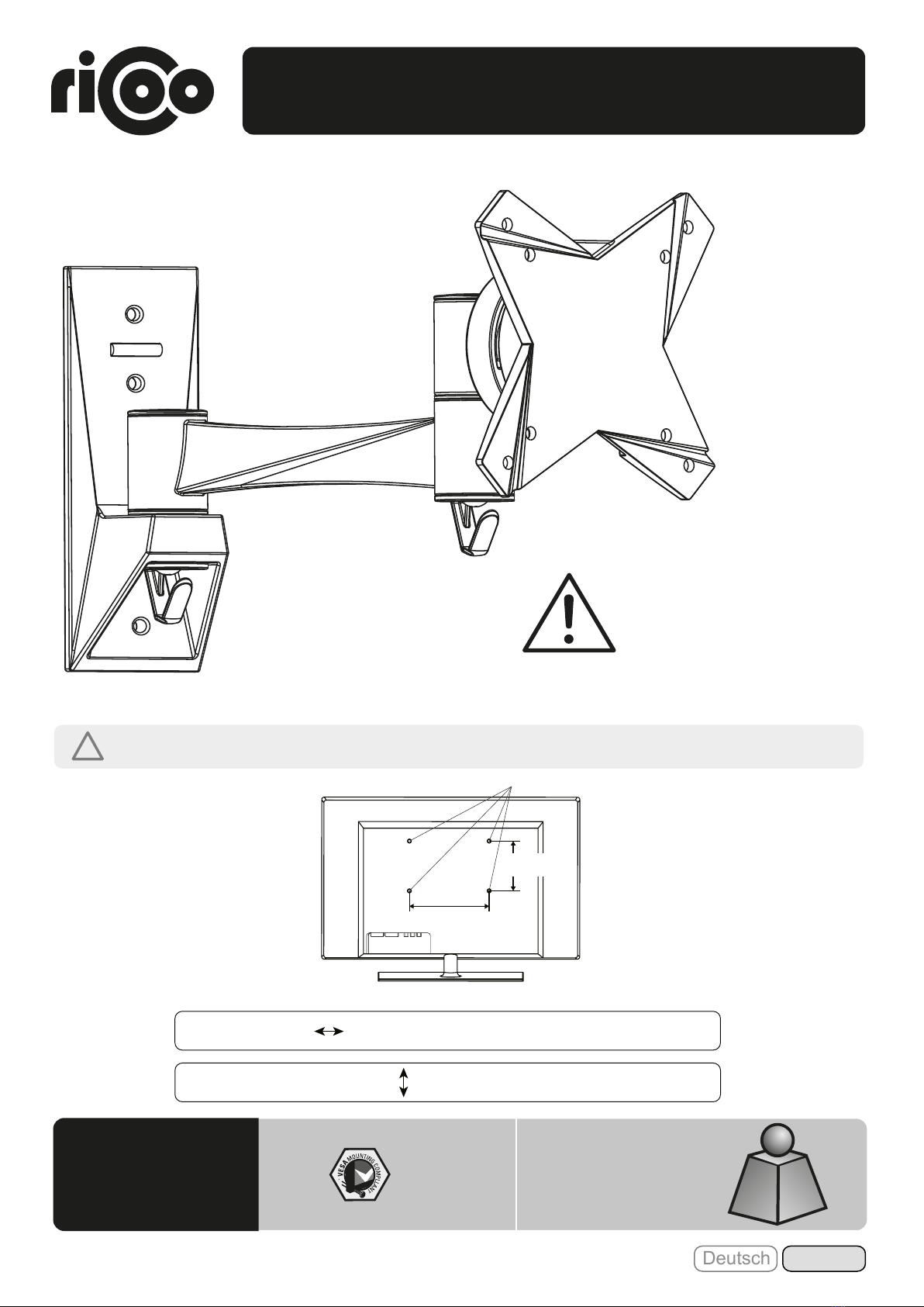
• Bitte beachten: Bilder in dieser Montageanleitung stellen nur technische Darstellung des Produktes dar. Tatsächliches Produktdesign kann
minimal abweichen.
• Beginnen Sie nicht mit der Montage, bis Sie alle Anweisungen und Warnungen, welche in dieser Montageanleitung vorhanden sind, durch-
gelesen und verstanden haben. Wenn Sie Fragen zu den Anweisungen oder Warnungen haben, kontaktieren Sie bitte Ihren Händler.
• Dieses Produkt darf NUR, wie in dieser Anleitung beschrieben, installiert und verwendet werden. Unsachgemäße Installation dieses Produkts
kann Schäden verursachen oder zu schweren Verletzungen führen.
• Dieser Artikel darf nur vom Fachpersonal montiert / installiert werden.
• Stellen Sie sicher, dass die Anbaufläche das Gesamtgewicht von diesem Produkt inkl. aller angeschlossener Komponente sicher tragen kann.
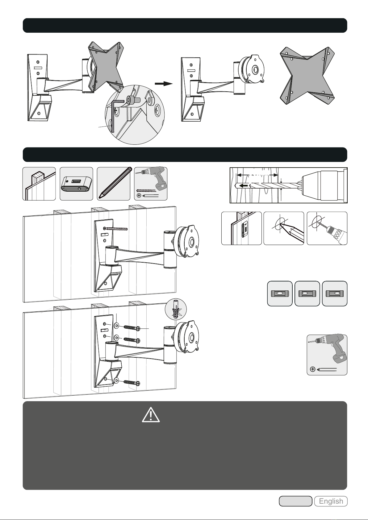
• Bei der Montage an die Holz-Wandbalken, stellen Sie sicher, dass die Befestigungs- schrauben in der Mitte der Balken verankert sind. Die
Verwendung eines Balkenfinders wird dringend empfohlen.
• Verwenden Sie immer eine technische Vorrichtung oder lassen Sie sich von einer zweiten Person unterstützen, wenn Sie die Konstruktion oder
angeschlossene Komponente heben oder ausrichten möchten.
• Ziehen Sie die Schrauben fest an, jedoch nicht überziehen / überdrehen. Überziehung der Schrauben kann zu Schäden an der Konstruktion
führen und reduziert die Haltbarkeit der gesamten Konstruktion.
• Dieses Produkt ist nur für den Innenbereich gedacht. Verwendung dieses Produkts im Freien kann zu Produkt- und Personenschäden führen.
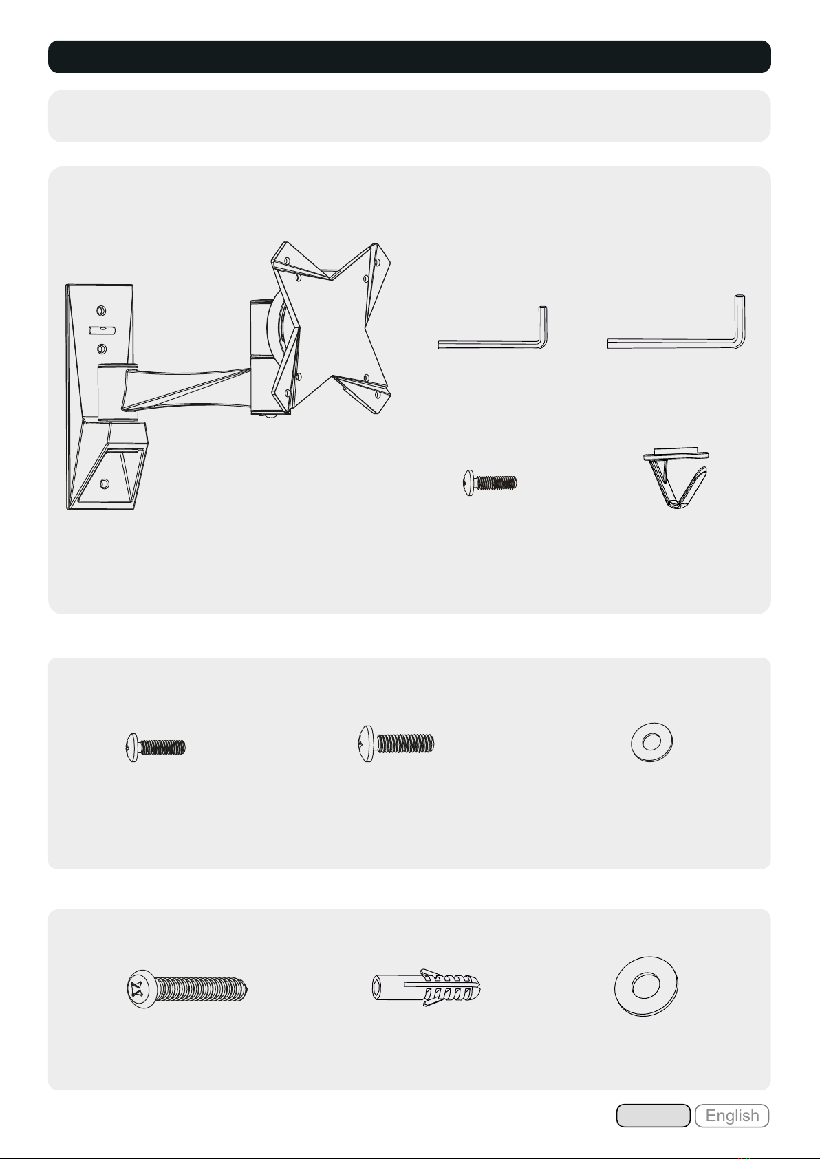
Aufgrund zahlreicher Fernseh-Bauarten auf dem Markt, können wir unser Bildschirm-Montagematerial nicht auf jedes
Bildschirm-Modell abstimmen. Deshalb kann es vorkommen, dass unsere mitgelieferten Schrauben, trotz Vielfalt, für Ihren
Fernseher/Monitor eventuell zu kurz oder zu lang sein können. Wir bitten um Ihr Verständnis, dass wir aufgrund vieler
Bildschirm-Modelle bzw. -Hersteller nicht alle Möglichkeiten abdecken können.
Da es von Wand zu Wand ebenso zu verschiedener Materialbeschaffung bis hin zum Spezialbedarf kommen kann, haben wir uns
auf die Lieferung von Montagematerial ausschließlich für die Massivbetonwand konzentriert. Wenden Sie unser mitgeliefertes
Montagematerial daher nur für die Massivbetonwand an.
• Sollten Sie Wände mit besonderen Materialansprüchen haben, raten wir Ihnen zu einer Fachmarkt-Beratung und
entsprechender Spezialbeschaffung an Montagematerial.
• Stellen Sie vor und während der Produktmontage, dass weder Sie noch andere Personen verletzt werden und keine Gegenstände beschädigt
werden. Holen Sie sich im Zweifelsfall Beratung bei einem Fachmann.
• Stellen Sie ebenfalls sicher, dass Sie und eventuelle Mithelfer oder beauftragte Personen vor der Montage die Montageanleitung, so wie diese
Warnhinweise zur Kenntnis genommen haben.
ACHTUNG: Lesen Sie die gesamte Bedienungsanleitung durch, bevor Sie mit der Montage beginnen.
S1611
E.N.Z. Engineering GmbH
Gewerbestr. 11
79364 Malterdingen
(Germany)
Tel: +49 (0) 7644-565310
Fax: +49 (0) 7644-5653199
E-Mail: support@ricoo.de
www.ricoo.eu
Artikeldaten
Kunden-Hotline
Liebe Kundin, lieber Kunde,
wir freuen uns, dass Sie sich für ein Produkt der Marke "RICOO" entschieden haben .
Manchmal trotz aller Bemühungen unsererseits Ihnen ein qualitativ hochwertiges Produkt
zu liefern, kann es vorkommen, dass einmal ein Zubehörteil fehlt oder ein Teil während des
Transports beschädigt wird .
In diesem Fall senden Sie den Artikel bitte nicht zurück, sondern fordern Sie einfach
Ersatz für das fehlende bzw. beschädigte Teil bei unserer Kunden-Hotline an . Kontakt-
daten von unserer Kunden-Hotline sind auf der rechten Seite aufgeführt.
Bitte nennen Sie bei der Kontaktaufnahme die Artikeldaten (auf der rechten Seite
aufgeführt), Artikelfarbe sowie die benötigten Teilnummern (inkl. benötigter Stück-
zahl), wie sie in dieser Anleitung unter dem Punkt "Lieferumfang" angegeben sind. Halten
Sie ebenfalls Ihre Bestellnummer / Order-ID für unsere Kunden-Hotline bereit. Wir
werden Ihre Anfrage umgehend bearbeiten !

Lieferumfang
WICHTIG: Stellen Sie vor der Montage sicher, dass alle Teile welche hier aufgeführt sind, bei der Lieferung dabei
sind. Sollten Teile fehlen oder defekt sein, kontaktieren Sie Ihren Händler.
Paket M
Paket W
Betonwand-Dübel (x3)
W-B D6 Unterlegscheibe (x3)
W-C
ST5.5x50 (x3)
W-A
Grundgerüst (x1)
A
D5 Unterlegscheibe (x4)
M-C
M5x14 (x4)
M-B
M4x14 (x4)
M-A
4mm Inbusschlüssel (x1)
C
3mm Inbusschlüssel (x1)
B
Kabel-Clip (x2)
E
M4x14 (x2)
D
3
English
Deutsch

Wandplatte an die
Wand anschrauben.
X X
√
WARNUNG
• Stellen Sie sicher, dass die Befestigungsschrauben in der Mitte der Balken verankert sind. Die Verwendung eines
Balkenfinders wird dringend empfohlen.
• Installateure sind dafür verantwortlich, die nötigen Werkzeuge für andere Arten von Einbausituationen zur Verfügung zu
stellen.
• Installateure müssen sicher stellen, dass die Anbaufläche das Gesamtgewicht von diesem Produkt inkl. aller
angeschlossener Komponente sicher tragen kann.
B
W-C
W-A
2
1
Montagelöcher
bohren.
3
Schritt 1
Holzbalken mit Balkenfinder
finden und die Montagelöcher
markieren.
Schritt 2a
ø 4mm
(ø 5/32”)
50mm
(2")
50mm
(2")
X
4
English
Deutsch

X X
√
Wandplatte an die
Wand anschrauben.
Installateure müssen sicher stellen, dass die Anbaufläche das Gesamtgewicht von diesem Produkt inkl. aller
angeschlossener Komponente sicher tragen kann.
WARNUNG
W-C
W-A
W-B
Montagelöcher
bohren.
1
2
Montagelöcher
markieren.
Schritt 2b
60mm
(2.4")
55mm
(2.2")
ø 8mm
(ø 5/16")
Achtung: Mitgelieferte Dübel
sind nur für Massivbeton-
wände geeignet!
!
5
English
Deutsch

Schritt 3
TV
TV
TV
oder
M-CM-A
M-B
M-C
M-A
M-B
Ziehen Sie alle Schrauben nach. ACHTUNG: Nicht überziehen!
· Wählen Sie die zu Ihrem TV passenden Schrauben.
· Montieren Sie die Frontplatte am Display.
· Fixieren Sie die Frontplatte mit Hilfe von den dazugehörigen Schrauben.
E
D
Schritt 4
E
D
6
English
Deutsch

Schritt 5
Wand
Schritt 6
Heben Sie das Display inkl. montierter Frontplatte an und hängen diese in das
Grundgerüst der Halterung ein. Ziehen Sie alle Schrauben (welche im
Schritt 1 entfernt wurden) wieder zu.
Schließen Sie die Kabel an Ihrem Fernseher
an und führen Sie die Kabel durch den
Führungsbügel.
ACHTUNG: Auf genügend Kabellockerung achten,
damit das Schwenken der Halterung nicht
beinträchtigt wird.
Wand
B
Wand
7
English
Deutsch

Schritt 7. Fertig!
Die TV-Halterung kann um 180° geschwenkt, um +/-15° geneigt oder
um 360° gedreht werden.
Wand
C
180°
Wartung
• Prüfen Sie in regelmäßigen Abständen (mindestens alle drei Monate), ob alle Schrauben an dem Produkt fest
angezogen sind.
• Bei Fragen kontaktieren Sie Ihren Händler.
Je nach Gewicht des Displays,
kann es notwendig sein,
Anpassungen an der Kugelgelenk-
Vorrichtung durchzuführen.
-15°
+15°
360°
180°
Fertig
8
English
Deutsch

S1611
75x75
100x100
15kg
(33lbs)
RATED
CAUTION: DO NOT EXCEED
RATED LISTED WEIGHT. SERIOUS
INJURY OR PROPERTY DAMAGE
MAY OCCUR!
INSTALLATION MANUAL
v.18.02
Wall Mount
for TV / Monitors
!
Please check BEFORE installation distance between mounting holes on your display!
Horizintally
Vertical /
Perpendicularly
VESA-Mounting holes
Display back
This wall mount supports the following distance between holes:
Horizontally
Vertical / Perpendicularly
75mm, 100mm
75mm, 100mm
9English
Deutsch

10 English
Deutsch
WARNING
• Please note: Images in these assembly instructions are only technical presentation of the product. Actual product design may vary
minimally.
• Do not begin the installation until you have read and understood all the instructions and warnings contained in this installation sheet. If you
have any questions regarding any of the instructions or warnings, please contact your local distributor.
• This product was designed to be installed and used ONLY as specified in this manual. Improper installation of this product may cause
damage or serious injury.
• This product may only be assembled / installed by the technical staff.
• Make sure that the supporting surface will safely support the combined weight of the equipment and all attached hardware and
components.
• When mounting on the wooden beams wall, make sure that the fastening screws are anchored in the center of the beams. It is highly
recommended to use a beamfinder.
• Always use an assistant or mechanical lifting equipment to safely lift and position the equipment.
• Tighten screws firmly, but do not over tighten. Over tightening can cause damage the items, this greatly reduces their holding power.
• This product is intended for indoor use only. Using this product outdoors could lead to product failure and personal injury.
By reason of large television construction types on the market, we can’t adjust our screen installation materials for each screen
type. Therefore it is possible that the screws which are numerously delivered don’t fit with your TV/Monitor. We ask for your
understanding that we can’t cover up all possibilities of many screen types.
Each wall is built up of different materials which can result a special requirement. Therefore we are concentrated on the delivery
of installation materials only for mass concrete walls. Use our included installation accessories only for mass concrete walls.
• If your walls have a special demand of materials, we advise you to ask in an expert shop for a suitable acquirement of the installation
materials.
• Make sure that before and after the installation of the product neither you nor somebody else can be injured and other objects can be
damaged. In case of doubt request for help from an expert.
• Make also sure that you and optionally the co-helper or representatives have registered the mounting instructions before the installation
and also the warning notice.
NOTE: Read the entire instruction manual before you start installation and assembly.
S1611
E.N.Z. Engineering GmbH
Gewerbestr. 11
79364 Malterdingen
(Germany)
Tel: +49 (0) 7644-565310
Fax: +49 (0) 7644-5653199
E-Mail: [email protected]
www.ricoo.eu
Product data
Customer-Hotline
Dear customer,
we are pleased that you have decided for a product of the brand "RICOO" .
Sometimes, despite our efforts to provide you with a high-quality product, it may happen
that an accessory is missing or a part is damaged during transport . Please do not
return the item in such a case, simply request replacement for the missing or damaged
part at our customer hotline .
Contact details from our customer hotline are listed below.
When contacting us, please mention the article data (listed on the right side),
article color as well as the required spare part numbers (including the required
quantity of items), as indicated in the "Scope of delivery" section of this manual.
Please keep ready your order number / order ID for our customer hotline. We will process
your request immediately !

Component Checklist
IMPORTANT: Ensure that you have received all parts according to the component checklist prior to installation.
If any parts are missing or faulty, telephone your local distributor for a replacement.
Package M
Package W
concrete anchor (x3)
W-B D6 washer (x3)
W-C
ST5.5x50 (x3)
W-A
Wall mount (x1)
A
3mm Allen key (x1)
B
4mm Allen key (x1)
C
M4x14 (x2)
D
Cable clip (x2)
E
D5 washer (x4)
M-C
M5x14 (x4)
M-B
M4x14 (x4)
M-A
11 English
Deutsch

Screw the wall
mount onto
the wall
X X
√
WARNING
• Make sure that mounting screws are anchored into the center of the studs. The use of a stud finder is highly recommended.
• Installers are responsible to provide hardware for other types of mounting situations.
• Installer must verify that the supporting surface will safely support the combined weight of the equipment and all
attached hardware and components.
2
1
Drill pilot holes
3
Step 1
Find and mark the
exact location of
mounting holes.
Step 2a
ø 4mm
(ø 5/32”)
50mm
(2")
50mm
(2")
B
W-C
W-A
X
12 English
Deutsch

X X
√
Screw the wall
mount onto
the wall
Installer must verify that the supporting surface will safely support the combined weight of the equipment and all
attached hardware and components.
WARNING
Drill pilot holes
1
2
Mark the exact
location of
mounting holes
Step 2b
60mm
(2.4")
55mm
(2.2")
ø 8mm
(ø 5/16")
W-C
W-A
W-B
Warning: Supplied plastic
anchors are only suitable for
solid concrete walls!
!
English
Deutsch
13

Step 3
or
Tighten all screws but do not over tighten.
Screw the VESA plate onto the display.
TV
TV
TV
M-CM-A
M-B
M-C
M-A
M-B
E
D
Step 4
E
D
English
Deutsch
14

Step 5
wall
Step 6
Lift display slowly and hook the head of VESA plate over VESA plate
mount rail. Tighten screws (removed in step 1) with a proper Allen key.
Connect the cables to your display and run
the cables through the wire clip.
Note: Leave slack in the cable for arm
movement.
wall
B
wall
15 English
Deutsch

Step 7. Done!
Adjust to the desired position or tilt.
wall
C
180°
Maintenance
• Check that the bracket is secure and safe to use at regular intervals(at least every three months).
• Please contact your distributor if you have any questions.
It is necessary to slightly loosen
or tighten the adjustment screws
using a proper Allen key according
to the weight of the display installed.
-15°
+15°
360°
180°
Done
16 English
Deutsch
Table of contents
Languages:
Other ricoo TV Mount manuals