MAINTENANCE
Recommended Service Intervals
Ridewell Suspensions recommends the following minimum service intervals for standard duty, on-highway
usage applications. More frequent intervals are recommended for heavier duty applications.
Daily/Pre-Trip Inspections
___ Check tires for proper inflation, damage or
excessive wear.
___ Check wheel-ends for obvious signs of lubricant
leakage. Check for missing components.
___ Check
axle assemblies for damage or loose
components.
___ Visually inspect suspension structure for signs of
damage or excessive wear.
___ Check for loose or missing bolts/nuts. Check for
irregular movement in suspension components.
___ Make sure air controls are operating properly.
Drain all moisture from air reservoirs.
First 6,000 miles of use
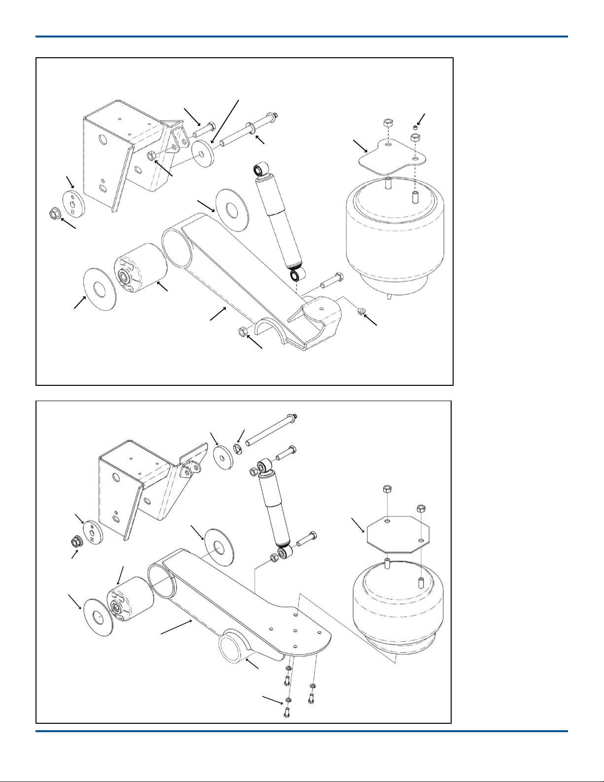
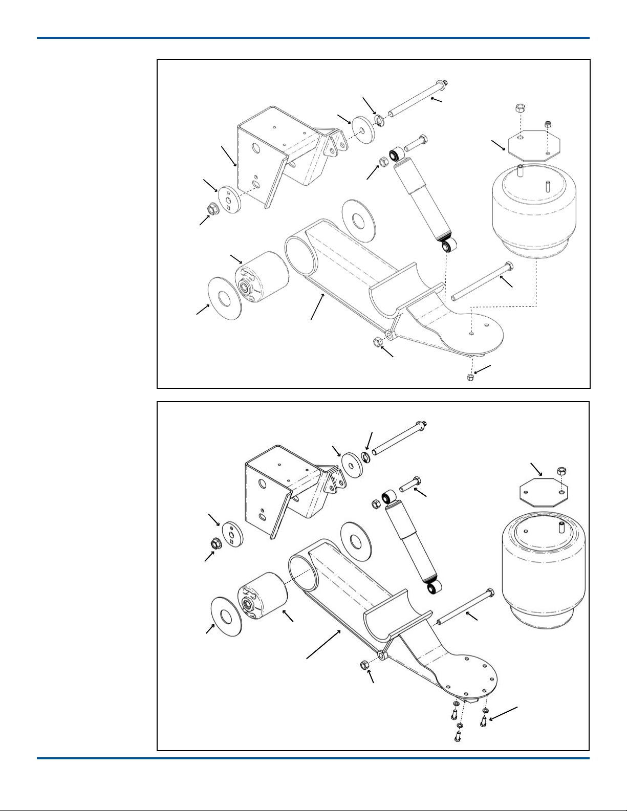
___ Torque suspension components to specifications
(Page 12/Engineering Drawing).
NOTE: Do not re-torque shear-type pivot bolt.
___ Verify that suspension is operating at the installed
ride height.
Every 12,000 miles of use
___ Inspect air springs for damage/excessive wear.
Torque air spring bolts/nuts to specifications
(Page 12/Engineering Drawing).
___ Check air lines and connections for leaks.
Every 50,000 miles of use
___ Torque suspension components to specifications
(Page 12/Engineering Drawing).
NOTE: Do not re-torque shear-type pivot bolt.
Annually/100,000 miles of use
___ Inspect pivot connection for worn pivot bushing
and wear washers. Replace if necessary.
___ Torque component bolts/nuts to specifications
(Page 12/Engineering Drawing).
___ Check arm beam-to-
axle connection welds.
Check lubrication level in wheel ends:
___ 1) Oil-Filled Wheel Ends:
Refill/Replace lubricant as needed
(TMC RP 631-“100K/Annual Inspection”).
___ 2) Semi-Fluid Grease:
Pull outer bearing and visually inspect the
lubrication level. Refill/Replace as needed
(TMC RP 631-“Level 3 Lubrication Level Inspection”)
(TMC RP 618-“Wheel Bearing Adjustment Procedure”).
___ Check air lines and connections for leaks.
___ Test air control system pressure protection valve
(PPV), if equipped.
___ Check height control valve (HCV) adjustment.
___ Verify suspension operating at installed ride height.
Failure to torque suspension components
to specications can result in suspension failure and
void the warranty.
Park the unloaded trailer on a level surface. Set the
brakes and chock the tires so vehicle cannot move
during inspection.
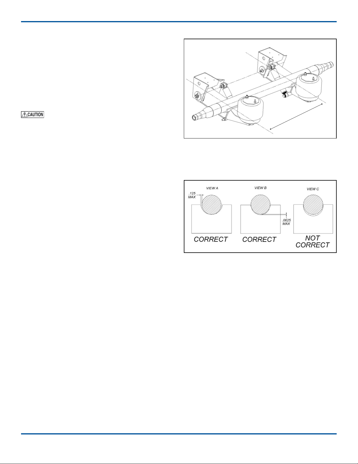
Insert the at end of a pry-bar between one side of
the hanger sidewall and the wear washers. Move the
pry-bar back-and-forth and look for excessive move-
ment of the beam (NOTE: A small amount of beam
Pivot Bushing Inspection Procedure
movement because of the rubber exing is normal).
Inspect the wear washers for excessive wear/damage.
Repeat the pry-bar process and wear washer inspec-
tion on the other side of the hanger. If any large/easy
movement or damaged wear washers is observed,
drop the beams for further inspection. Replace com-
ponents as necessary.
Refer to these Technology & Maintenance Council
(TMC) publications for additional information
RP 609 Self-Adjusting/Manual Brake Adjuster
Removal, Installation and Maintenance
RP 618 Wheel Bearing Adjustment Procedure
RP 619 Air System Inspection Procedure
RP 622 Wheel Seal and Bearing Removal,
Installation, and Maintenance
RP 631 Wheel End Lubrication Recommendations
RP 643 Air Ride Suspension Maintenance
RP 728 Trailer Axle Maintenance
Back to TOC Page 8 260-Trailer-ISM-RevK-03-11-21