Back to TOC Page 6 215T-Trailer-ISM-RevF-03-24-21
Suspension Mounting
Refer to the engineering drawing for the range of ride
heights available and clearance requirements .
The suspension installer has the nal responsibility
of aaching the suspension to the vehicle frame.
Weld-On Installation Procedure
Recommended locations of customer-furnished ller
plates and supporting crossmembers for the hang-
ers and air spring mounting plates are shown on the
engineering drawing.
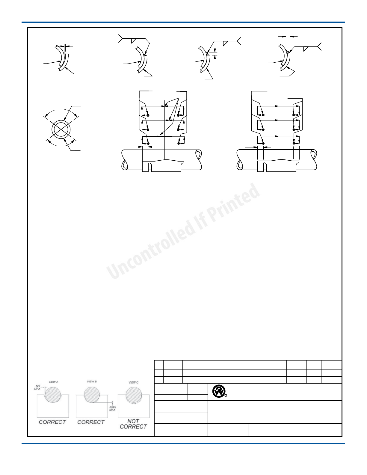
Welding method must use a minimum weld
tensile strength of 70,000 psi, per AWS specications.
1. Mark desired location of the hangers and ller
plates on the frame. Hangers must be installed
parallel to each other for proper axle alignment.
2. Mark the desired location of the air spring
mounting plates and ller plates on the frame.
NOTE: Protect other chassis components from
weld spaer during installation, if necessary.
3. Install ller plates for the hangers and air spring
mounting plates on the frame. Weld ller plates
to crossmembers with ¼” llet welds down the
length of the crossmember.
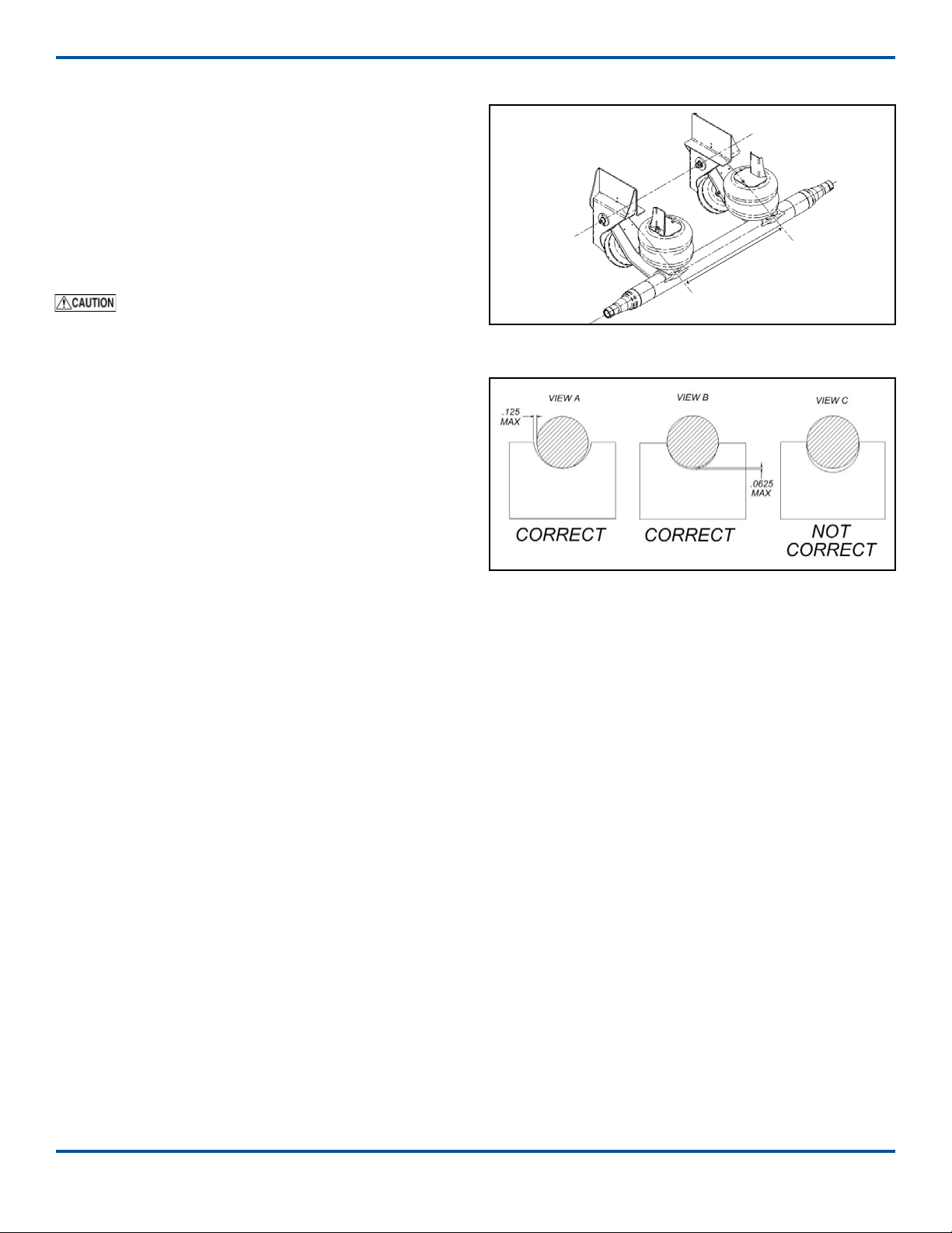
4. Weld the hangers to the frame/ller plates with
1/4” llet welds completely around the hangers.
Stop the welds 1/2” from the corners and edges.
5. Weld the air spring mounting plates to the frame/
ller plates with 3/16” llet welds.
6. Aach a crossmember or diagonal brace to the
front of the hangers with 1/4” llet welds.
Bolt-On Installation
Before installation, check to make sure that wires,
hoses or other components will not be aected by
drilling into the frame rail.
• Bolts/nuts for aaching the suspension to the
vehicle are supplied by the installer. Grade 8 bolts
and anged locknuts or locknuts with hardened
washers are recommended.
• Bolt holes are not provided in the air spring
mounting plates. Clamp mounting plates and
ller plates, if used, in place and drill (minimum)
two bolt holes in each mounting plate for installa-
tion onto the chassis.
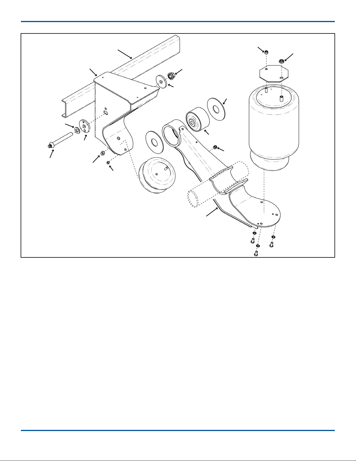
Final Assembly and Inspection
1. Verify welds of frame hangers and air spring
mounting plates.
2. Inspect for loose/missing fasteners on the sus-
pension assembly. Verify suspension component
bolts/nuts are torqued to proper values (Pg 12).
3. Install wheels and tires.
When lowering an auxiliary axle on
an unloaded vehicle, pressure to the load air
springs must be reduced to below 10 psi. Failure
to reduce the air pressure could cause the ve-
hicle’s drive axles to rise from the ground and the
vehicle could roll in an unsafe manner.
4. Check that tires are inated to recommended
pressure. Check wheel hubs for proper level of
lubricant recommended by the manufacturer.
5. Lift the axle to the raised position. Check the air
system tubing and connections for leaks.
6. Check that wheels can rotate freely and that
brakes and slack adjusters are properly adjusted.
7. Raise and lower the suspension assembly (wheels
and tires installed) through the entire range of
travel. Make sure that sucient clearances for air
springs, brake chambers and other components
has been provided.
Do not lower the auxiliary axle while the
vehicle is moving above 10 mph.
Shock Absorber Kit (Optional)
The shock absorber can be installed after the suspen-
sion has been assembled and mounted on the vehicle.
Installation Procedure
Refer to the shock kit engineering drawing for the
correct mounting locations and installation angles for
the upper and lower mounting brackets on individu-
al RCA-215 suspension models.
Welding method for lower mounting bracket
must use a minimum weld tensile strength of 70,000
psi, per AWS specications.
1. Disconnect and remove the load springs from the
suspension assembly. Protect the lift springs from
welding spaer.
2. Remove the upper air spring mounting brackets.
continued on next page