RIDGID NaviTrack Scout User manual

NaviTrack
Scout™
SEE ITFIND IT CLEAN IT

Battery Precautions:
.Use only the size and type of battery specified. Do
not mix cell types (e.g. do not use alkaline with
rechargeable). Do not use partly discharged and fully
charged cells together (e.g. do not mix old and new).
.Recharge batteries with charging units specified by
the battery manufacturer. Using an improper charger
can overheat and rupture the battery.
.Properly dispose of the batteries. Exposure to high
temperatures can cause the battery to explode, so do
not dispose of in a fire. Some countries have regulations
concerning battery disposal. Please follow all applicable
regulations.
.Use equipment only as directed. Do not operate the
Scout unless proper training has been completed and
the owners manual read
.Do not immerse the antennas in water. Store in a dry
place. Such measures reduce the risk of electric shock
and instrument damage.
.Check for breakage of parts, and any other condi-
tions that may affect the Scout’s operation. If dam-
aged, have the instrument serviced before using. Many
accidents are caused by poorly maintained tools.
.Use only accessories that are recommended by the
manufacturer for the Scout. Accessories that may be
suitable for one instrument may become hazardous
when used on another.
.Keep handles dry and clean; free from oil and
grease. Allows for better control of the instrument.
.Protect against excessive heat. The product should be
situated away from heat sources such as radiators, heat
registers, stoves or other products (including amplifiers)
that produce heat.
1.1 Service
°Diagnostic instrument service must be performed
only by qualified repair personnel. Service or mainte-
nance performed by unqualified repair personnel could
result in injury.
°Provide proper cleaning. Remove battery before
cleaning. Do not use liquid cleaners or aerosol cleaners.
Use a damp cloth for cleaning.
°Conduct a safety check. Upon completion of any serv-
ice or repair of this product, ask the service technician to
perform safety checks to determine that the product is in
proper operating condition.
°Damage to the product that requires service.
Remove the batteries and refer servicing to qualified
service personnel under any of the following conditions:
o If liquid has been spilled or objects have fallen into
product.
o If product does not operate normally by following the
operating instructions.
o If the product has been dropped or damaged in any
way.
o When the product exhibits a distinct change in per-
formance.
In any correspondence, please give all the information shown
on the nameplate of your tool including model number and seri-
al number.
1.2 Important Notice
The Scout is a diagnostic tool that senses electromagnetic
fields emitted by objects underground. It is meant to aid the
user in locating these objects by recognizing characteristics of
the field lines and displaying them on the screen. As electro-
magnetic field lines can be distorted and interfered with it is
important to verify the location of underground objects before
digging.
Several utilities may be underground in the same area. Be
sure to follow local guidelines.
Exposing the utility is the only way to verify its existence, loca-
tion and depth.
Ridge Tool Co., its affiliates and suppliers, will not be liable for
any injury or any direct, indirect, incidental or consequential
damages sustained or incurred by reason of the use of the
Scout.Several utilities may be underground in the same area.
Be sure to follow local guidelines.
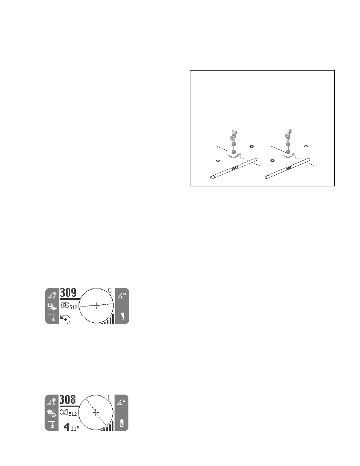
The ScoutTM sonde and line locator uses multi directional
antennas and advanced processing to make pinpointing sondes
and tracing buried utility lines fast, accurate and easy.
2.1 What are Its Unique Features?
Scout’s advanced technology gives several unique features
over conventional locators:
• Multi Directional Antenna System.
2
READ THE ENCLOSED SAFETY INSTRUCTIONS.
SAVE THESE INSTRUCTIONS!
OPERATING INSTRUCTIONS
GENERAL SAFETY INFORMATION
WARNING! Read and understand all instructions. Failure
to follow all instructions listed below may result in electric
shock, fire, and/or serious personal injury.
2. Introduction to the Scout
1. Scout Use and Care

3
• Micro Map View.
• Indicate distinct signal characteristics.
2.2 What Does It Do?
The Scout is used above ground to sense electromagnetic
fields emitted from underground or hidden lines (electrical con-
ductors like metal wires and pipes) or sondes (actively trans-
mitting beacons). When the fields are simple and undistorted,
then the sensed fields are representative of the buried object.
The Scout locates conductive objects emitting a field; it does
not directly sense underground objects.
Electrical fields emitted by buried objects can be of two types;
the first type is emitted by long conductors such as energized
wires, inspection camera pushcables or pipes. These objects
produce a long cylindrical field and this is often referred to as
“Line” tracing.
(Passive, AC Tracing is just a special case where the line is
“energized” with electrical power.)
The second type, sondes (also called transmitters, beacons, or
active duct probes), emit a differently shaped field and the
Scout is programmed to measure and display this type of field.
The more complex field shape of a sonde is called a dipole
field, and is the same as that produced by a bar magnet and
our planet Earth.
Electromagnetic fields have three (3) important properties:
frequency, strength and angle (direction). Unlike conventional
locators, which can only measure strength in the direction of
the individual antenna(s), the Scout measures both signal
strength and field angles in three dimensions (3D). This
enhanced capability makes the mapping display possible. The
experienced operator can use this additional information to
speed the locating process and to help sort out complex locat-
ing situations. On the other hand, the occasional or novice
user can easily locate using signal strength alone.
The Scout locating rule #1 is make the number big! –
Maximizing signal strength is the key, primary locating method.
Whether line tracing or locating a sonde, maximum signal
strength occurs over the target. Depth is displayed when over
the target.
2.3 What Is The Scout Multi Directional
Advantage?
Viewing all of the signal with Multi directional antennas offers
definite advantages:
1. Signal always gets stronger as user gets closer to the
target.
2. Eliminates Nulls and ”Ghost Peaks”. A conventional
locator signal has a peak, then a null and then a small-
er peak. This can confuse the operator, especially if
they interpret a smaller peak as the target (known as
“Ghost” or “False” peaks). The Scout sees just one peak
to draw the user to the target.
The field emitted by a charged line.
The dipole field emitted by a sonde.
Example of how the Scout maximizes directly
over the sonde.

4
3. How the unit is held does not affect signal strength. The
user can approach from any direction and does not
need to know the lie of the pipe or wire.
4. Additional tools to identify and solve “difficult” locates
include a graphical micro map and an angle indicator to
help interpret signal characteristics.
2.4 What Is The Micro Map Advantage?
The map provides graphics that shows the signal’s charac-
teristics. It is a bird’s eye view of the signal underground,
shown graphically on the screen. It is used as a guide for
tracing underground lines and can be used to better pinpoint
sondes. It can also be used to provide more information for
complex locates.
By moving the locator over the ground the Scout passes over
the signal emitted by the underground objects. This allows the
user to see on the screen, visualizations of the signal and then
mark them. Conventional locators cannot map the under-
ground signal as their antennas cannot see the complete
shape of it.
Sonde signal as “seen” by a conventional loca-
tor. Main peak in center and two false peaks
outside the two nulls.
Sonde signal as “seen” by the Scout. Only one
peak, no nulls.
3. Scout Components

5
Display Screen

4.1 Installing/Changing Batteries
To install batteries into the Scout turn the unit over to access
the battery compartment. Turn the knob on the battery cover
counter clockwise. Pull straight up on the knob to remove the
door. Insert the batteries as shown on the inside decal and
make sure they drop to full contact.
Fit the door into the case and turn the knob clockwise while
lightly pressing down to close. The battery cover can be
installed in either orientation.
When the Scout is turned on it takes a few seconds to check the
batteries. Until then the battery level will show as “empty”.
Warning! – Do not allow debris to fall into battery compart-
ment. Debris in the battery compartment may short the battery
contacts, leading to rapid discharge of the batteries, which
could result in electrolyte leakage or risk of fire.
4.2 Operation Time
Typical operation time for the Scout locator, when using alkaline
cells, ranges from about 12 to 24 hours depending on factors
such as sound volume, and how often the backlight is on. Other
factors that affect the operation time will include chemistry of the
battery (many of the new high performance batteries, such as
the “Duracell ® ULTRA” do last 10%-20% longer than conven-
tional alkaline cells under high demand applications). Operation
at low temperatures will also reduce battery life.
To preserve battery life the Scout will automatically shut down
after 1 hour of no key presses. Simply turn the unit on to
resume use.
4.3 Powering Up and Down
Turn the power on by depressing the Power key on the
keypad. The RIDGID®logo displays, the software version num-
ber will appear in the lower right corner.
6
Volume Control Key – opens and closes the Sound Level menu.
Sonde/Trace/Frequency Mode Key – switches active frequencies and functions.
Up Key – scrolls up through menu choices.
Select Key – selects the highlighted choice when a menu is open.
Down Key – scrolls down through menu choices.
Menu Key – opens/closes the menu.
Power ON/OFF Key – turns the Scout on or off.
Keypad
4. Getting Started

7
Turn the unit off by depressing and releasing the Power key on
the keypad. Be aware there is a delay of a few seconds
while turning on/off the unit.
4.4 Low Battery Warning
When the battery gets low, a battery icon will appear in the
map area on the screen. This indicates that the batteries need
to be changed and that the unit will soon shut down.
Just before complete shut down there will be a non-interrupt-
able power down sequence.
In some cases the voltage on rechargeable batteries may drop
so quickly that the unit will just shut down. The unit will turn off
and restart. Just replace the batteries and turn the unit back on.
Once the Scout is up and running the next step is to set up the
frequencies needed that match the equipment to be located.
Each is activated for use by selecting them from a list in the
menu.
1. Push the menu key, highlight the selection, then press
the select key to activate:
2. Using the up and down arrows highlight a frequency to
match the one used in the sonde or on the line trans-
mitter, then press the select key to check the box. See
the Menu Choices for reference. Hit the menu key to
return to the main screen.
Warning! – Be sure that the frequency selected matches the
desired use. 512 and 33 are available as a sonde AND a line
trace frequency. Using a sonde frequency for line tracing or
vice versa, can cause the Scout to display incorrect depth
information.
3. Now press the sonde/trace/frequency mode key to
cycle through the activated frequencies and modes.
Pay attention to the icons on the screen to see which
mode the Scout is operating in.
4. If the depth, auto backlight or LCD contrast needs to be
adjusted then highlight the selection in the tools section
of the menu and make changes using the select key.
5.1 Menu Choices
5. Set up
128

5.2 Sounds of the Scout
The sound is related to increasing or decreasing signal strength.
It rises in pitch and volume when signal increases, or down
when signal decreases. As the signal ramps up, it will step in
pitch and volume on the way up only to help push the operator
to the maximum signal strength. If the signal strength drops, the
sound returns to a base tremolo as if it saw no signal.
The Scout has an automatic gain. When the gain moves up or
down a step the sound will reset to the higher or lower intensity.
Adjust the sound volume by pressing the Sound Key.
The volume will move with each press of the sound key or the
up and down arrows can be used to adjust the volume as well.
Press the select key to exit this screen.
Note – Pressing the select key during normal operation will
center the pitch to a medium level.
5.3 Overview - Understanding sondes and the
Scout
Sondes (also called transmitters, beacons or active duct
probes) emit an electro-magnetic field very similar to the mag-
netic field that emanates from the Earth.
In fact, if the Earth were turned on its side, its magnetic field
would look a lot like the field from a sonde.
As a locator, the Scout can measure the shape (angle) of the
field lines from a sonde and identify distinct characteristics of
these lines. Three important characteristics are the two
POLES and the EQUATOR. At the Poles the angle of the sig-
nal is 90 degrees (vertical). At the Equator it is 0 (horizontal).
Poles are distinct points in space, while the Equator wraps
completely around the sonde. Since these distinct characteris-
tics are constant, they can be used to accurately pinpoint the
location of the sonde.
Poles usually occur where conventional locators would experi-
ence “nulls”, the dead spots that occur when the signal pass-
es through their antennas vertically. The difference is that
Scout can “see” the Poles (“nulls”) and show you where they
are, even when you’re not directly over them, and no mat-
ter how Scout’s antennas are aligned with the signal.
This is one reason why locating with Scout is so much easier
than with conventional locators.
The sonde is located at the point where the Equator passes
directly between the two Poles.
5.4 Locating the sonde
The Scout can be used to locate the signal of a sonde (trans-
mitter) in a pipe, so that its location can be identified above
ground. Sondes can be placed at a problem point in the pipe
using a camera push rod or cable. They can also be flushed
down the pipe.
The following assumes that the sonde is in a horizontal
pipe, the ground is approximately level and the Scout is
held with the antenna mast vertical.
Important! – Signal strength is the key factor in determining
the sonde’s location. To ensure an accurate locate, you MUST
take care to maximize the signal strength prior to marking an
area for excavation.
5.4.1 When locating a sonde set up the locate in the
following manner:
.Before putting the sonde in the line, use the Scout to
make sure it’s operating and that Scout is receiving its
signal.
.Once the sonde is in position and transmitting, activate
the sonde and match the same frequency as the sonde
on the Scout. Make sure it has a sonde mode icon
8

9
Warning! – Be sure that the frequency selected matches the
desired use. 512 and 33 are available as a sonde AND a line
trace frequency. Using a sonde frequency for line tracing or
vice versa, can cause the Scout to display incorrect depth
information.
.Go to the suspected sonde location. If the direction of
the pipe is unknown, push the sonde a shorter distance
into the line (~5m from the access, is a good starting
point).
5.4.2 Next, use one of the following methods to locate
the sonde:
Method 1 – Maximize Signal Strength
1. Hold the Scout so the mast is out away from your body.
Sweep the mast in the suspected direction of the sonde
while observing the signal strength and listening to the
sound. The signal will be highest when the mast is
pointing to the sonde.
2. Lower Scout to its normal operating position (mast verti-
cal) and walk in the direction of the sonde. As you
approach, the signal strength will increase and the
audio tone will ramp and rise in pitch. Use the signal
strength and the sound to maximize the signal.
3. Once the maximum has been found, place the Scout
close to the ground over the peak and move in all direc-
tions to make sure that the signal drops off.
Note – The highest signal counts, the equator line can be on a
different position than the highest signal if the sonde is tilted
(see section tilted sonde).
Method 2 – Follow the Equator – Then Maximize
1. Works best in unobstructed, open areas, when the
sonde is expected to be horizontal. Sweep the mast
and then walk in the direction of maximum signal
strength as in Method 1.
2. When the Scout displays a steady Equator line cen-
tered on the screen, follow it towards increasing signal
strength. When maximum signal strength is reached
move the Scout along the Equator and in all directions
to be sure that it is on the peak.
When the Sonde is tilted be sure the find the maximum signal
as that is the place where the sonde will be.
Verify the locate.
1. At the point of maximum signal strength, and with the
mast vertical, move the Scout perpendicular to the
Equator line on the screen. When the Pole icon
appears move Scout until the Pole icon is centered on
the crosshairs with the lower antenna ball on the
ground. Place one of the triangle orange markers on
the ground at this spot.
2. Move Scout back across the Equator line to the other
pole. Center the crosshairs on the second Pole icon
and mark its position as before.
View when Scout is on the pole.

3. Move back to the maximum signal strength. Mark this
point on the ground with the yellow hexagon marker
chip. Move the lower antenna ball slowly away from the
yellow marker in all directions while observing the signal
strength display. The signal strength should be highest
directly over the sonde.
4. Look to see that all three markers are aligned and that
the yellow hexagon marker is approximately halfway
between the Pole markers.
If the yellow marker is not in the middle, see the section on tilt-
ed sondes.
Important! – Being on the Equator does NOT mean you’re
over the sonde! Remember that signal strength is the key fac-
tor in locating the sonde. You must be at the point of highest
signal strength.
For best accuracy use the bubble level. The mast MUST be
vertical when marking the Poles and Equator, or their locations
will be incorrect!
5.5 Measuring Depth
The Scout measures depth by comparing the strength of the
signal at the lower antenna to the upper antenna.
Depth is measured when the bottom antenna is touching the
ground directly above the signal source.
1. To measure depth, place the locator on the ground,
directly above the sonde or line. Make sure that the
angle indicator reads 5 degrees or less. Then slowly
rotate the unit in the direction of the arrow shown on the
bottom left of the screen until the depth appears.
The bubble level is useful when measuring depth to make sure
that the antenna mast is vertical.
In order to maximize signal and achieve a more accurate
depth reading, the Scout needs to be rotated to align the
antenna with the signal.
2. Depth will be shown in the lower left hand corner.
3. Force Depth Feature - If the angle indicator reads
higher than 5 degrees then the Scout will not give a
depth measurement. Press the down arrow key and
hold it. This will force the depth if depth can be meas-
ured (see the following section on tilted sondes).
5.6 Operating Tips for Locating a sonde
.Use the sound when possible to help guide the Scout to
the maximum signal strength.
.If the Equator is crossed, and the signal is not maxi-
mized, follow the Equator to the highest signal strength.
Simply finding the Equator of the sonde (the dashed
line on the screen) does NOT indicate that the sonde
has been found. The point of maximum signal strength
must also be found. If the sonde is steeply tilted, the
Equator will NOT lie directly above the sonde and the
distance from the sonde to each Pole will not be equal.
If the sonde is tilted, maximize the signal.
.Always confirm the point of maximum signal strength.
Verify what the map is showing, unless it is known for a
fact that all the required conditions have been met. The
map assumes the following conditions:
1. The ground is level.
2. The sonde is level.
3. The Scout Locator is above ground level.
4. The Scout Locator is held approximately vertical,
antenna mast pointing straight down.
If these conditions are not met, pay close attention to maximiz-
ing signal strength. In general, if the above conditions are true
and if the Scout is within about two “depths” of the signal
source, the map will be useful and accurate. Be aware of this
when using the map if the target or signal source is very shal-
low. The useful search area using the map alone can be small
if the sonde is extremely shallow.
10
When checking the depth always take a measurement,
then rotate the Scout 180 degrees (1/2 circle) and take
another depth measurement. Be sure that the lower ball
stays at the same position on the ground and the mast is
vertical. If the depth readings are not within about 10% of
each other then distortion is present and the depth read-
ing should be questioned.

11
5.7 Tilted sondes
If the sonde is tilted, one Pole will move closer to the sonde
and the other farther away so that the sonde location no
longer lies midway between the two poles. The signal strength
of the nearer Pole becomes much higher than that of the more
distant Pole. In the extreme, as the sonde tilts to vertical, the
one Pole moves to a point directly above the sonde and this
Pole will also correspond to the point of maximum signal
strength. The other Pole will not be seen. Therefore even if the
sonde is vertical, as it could be if it fell into a break in the line
or an underground tank, the sonde can still be located.
What is seen on the screen is a Pole of maximum signal
strength when the sonde is vertical.
The multi directional antennas allow the depth to be measured
even if the sonde is tilted. In this circumstance the force depth
feature must be used to take a depth measurement (see
Measuring Depth).
Micro map - Examples – Sonde Mode
Scout on the Pole
Scout leaves the
Equator and
approaches the Pole
Scout on the Equator

The Scout can also be used to trace a pipe or line so that the
ground above it can be marked. This identifies the line’s loca-
tion so that it can be avoided during a dig or exposed for repair
or replacement. The Scout can locate energized lines with a
variety of frequencies or it can be used passively to conduct a
sweep to locate any long conductors carrying signals.
Underground lines are energized with a line transmitter. This
active signal is then traced using a receiver such as the Scout.
1. Attach the line transmitter to the line according to the
manufacturer’s instructions.
A “transmitter” is a generic name used for anything that gener-
ates a locatable signal. It is used to describe a sonde as well
as the device that is used to energize a cable or pipe.
2. Match the frequency used on the transmitter with the
same frequency on the Scout. Be sure it has a line trace
icon . Push the main menu button to return to the
locate screen.
3. When beginning the trace it is recommended that signal
strength be observed first to see if it drops when the
Scout is pulled away. Point the mast at the leads or the
transmitter itself if using inductive mode. Over the line it
should peak and drop off on either side. If the signal
strength and lines on the screen DO NOT agree then
the signal may be distorted.
4. When tracing, the way the pipe or cable is running will
be shown on the screen with 2 solid lines. Keeping the
lines on the center indicates that the Scout is tracing
the line underground. If the line moves off to the left or
right then move the Scout to get the line back on cen-
ter. The signal emitted from a line is strongest directly
over that line. If that is not the case then distortion is
present.
Note – When using a line trace frequency there are two lines
on the screen. When using a sonde frequency the Equator is a
single line.
Caution – Care should be taken to watch for signal interfer-
ence that may give inaccurate readings. Depth readings
should be taken as estimates and actual depths should be ver-
ified by exposing the line before digging.
5. When beginning the trace it is recommended that signal
strength be observed first to see if it drops when the
Scout is pulled away. Point the mast at the leads or the
transmitter itself if using inductive mode. Over the line it
should peak and drop off on either side. If the signal
strength and lines on the screen DO NOT agree then
the signal may be distorted.
6.1 Tracing a Passive AC Line
In passive mode the Scout senses alternating current, or AC
fields. Buried power lines typically do not emit any traceable
signal unless power is flowing in the wires. For example street
lights that are turned off are hard to trace passively.
1. Select a Passive AC Trace Frequency with the passive
line trace icon .
2. The Scout has two (2) passive AC tracing frequencies
that are standard. They are 50Hz and 60Hz.
6.2 Operating Tips for Line Tracing
.When the lines are not centered on the map, but
signal strength is maximized, distortion is present!
a. Try changing the frequency used to a lower one.
b. Move the ground stake position away from the line
to be traced.
c. Make sure that the line is not commonly bonded to
another utility.
.If the lines will not center or if they move across the
screen inexplicably, then the Scout may not be receiv-
ing a clear signal.
a. Check the transmitter to be sure that it is operating
and well grounded.
b. Test the circuit by pointing the lower antenna at
either transmitter lead.
c. Check that the Scout and transmitter are operating
on the same frequency.
d. Try different frequencies, starting with the lowest,
until the line can be picked up dependably.
6. Tracing a Line with Scout
12

13
.Current flows best from the smallest lines to the largest
(lowest resistance) lines. An example would be tracing
a pipe from the house to the street.
.While tracing, the signal should maximize, and the
depth minimize, at the same place where the lines cen-
ters on the display. If this is not the case, the utility may
be turning or other coupled signals may be present.
.Higher frequencies bleed over more but may be need-
ed to jump breaks in tracer wires or go over insulating
couplers.
.When using the transmitter inductively be sure to begin
the locate 10/15m away to avoid “air coupling”. This is
where the Scout will pick up the signal from the trans-
mitter directly and not from the line to be traced.
While tracing the micro map assumes the following conditions:
a. The ground is level.
b. The line is level.
c. The Scout Locator is above ground level.
d. The Scout antenna mast is held approximately verti-
cal.
.If these conditions are not met, pay close attention to
maximizing signal strength. In general, if the Scout is
within about two “depths” of the line, the map will be
useful and accurate. Be aware of this when using the
micro map if the target or line is very shallow. The use-
ful search area in micro map can be small if the line is
extremely shallow.
Micro map - Example – Line Trace

7.1 Change of Depth Units
The Scout can change the units that it measures depth in to
either Feet or Meters. To change these settings simply high-
light the depth icon in the Tools Menu and then press the
select key to toggle between feet or meters.
7.2 Auto Back Light
Low light levels are sensed by a light detector built into the
upper left corner of the keypad. The backlight can be forced on
by blocking the light to this sensor with a thumb.
The automatic LCD backlight is factory set to only turn on
under fairly dark conditions. This is to conserve battery power.
As the batteries near depletion, the backlight will appear dim.
Near the end of battery life, the backlight operates at a very
low level to conserve battery power.
To turn the backlight off, highlight the light bulb icon in the tools
section of the menu and press the select key to toggle
between Auto and OFF.
7.2.1 LCD Contrast
When this is highlighted and selected the LCD contrast can be
adjusted with the up and down arrows.
8.1 Signal Interference
8.1.1 Distorted Fields
Sometimes a single field may encounter metal or other ferrous
material in the ground that may distort the field lines. It may be
another utility, buried scrap or old unused lines that can shunt
or shorten the field lines. In this case the Scout may display a
weaker signal around the object and a stronger signal directly
above it. The object may act as a lens that amplifies or weak-
ens signal unpredictably.
8.1.2 Composite Fields
Composite fields are also possible. Where a single field meets
another, the two, or more, may create a stronger signal. It is
important for operators to understand this around “Ts” or right
angles in the line, where composite fields are often encountered.
8.1.3 Noise
Interfering signals (noise) are simply part of the locating chal-
lenge. Interference can either be at the same frequency being
used, or it can be “out of band” at other frequencies. Some of
the largest interfering signals are generated by power trans-
mission equipment. Power transformers, large electric motors
or generators and lines can be the source of very large noise
signals. Areas that are particularly noisy should be avoided if
possible.
If the angle display is unstable and not steady, and/or if the
signal levels are not steady, this is a good indication of either
no target signal present (sonde or energized line), or a high
level of interfering noise.
8.2 Notes on Accuracy
Depth and Signal Strength measurements rely on a strong sig-
nal being received by the Scout. Remember that the Scout is
used above ground to sense electromagnetic fields emitted
from underground lines (electrical conductors like metal wires
and pipes) or sondes (actively transmitting beacons). When
the fields are simple and undistorted, then the sensed fields
are representative of the buried object.
If those fields are distorted and there are multiple interacting
fields, it will cause the Scout to locate inaccurately. Locating is
not an exact science. It does require the operator to use judge-
ment and look for all the information available beyond
14
Composite field shown around a connection in
the line.
7. Tools Menu
8. Useful information

15
what the instrument readings may be. The Scout will give the
user more information but it is up to the operator to interpret
that information correctly. No locator manufacturer will claim
that an operator should follow the information from their instru-
ment exclusively.
Conditions when locating accuracy must be questioned:
.When other lines or utilities are present. “Bleed over”
may produce distorted fields and illuminate lines uninten-
tionally. Use lower frequencies when possible and elimi-
nate all connections between the two lines.
.When using the transmitter inductively. This gives
the line a weak signal. Use a direct connection whenev-
er possible.
.When T’s or splits are present in the line. Can cause
distortions in the signal.
.When signal strength is low. A strong signal is neces-
sary for accurate locating.
.When soil conditions vary. Extremes in moisture,
either too dry or overly saturated, may affect measure-
ments. For example ground saturated with salty water,
that might be found by the coasts, will shield the signal
severely and be very difficult to locate in.
Before transporting make sure that the unit is turned off to pre-
serve battery power.
When transporting make sure that the unit is secure and does
not bounce around or gets bumped by loose equipment.
The Scout should be stored in a cool dry place.
If storing the Scout for an extended period of time, the batter-
ies should be removed.
The Scout also comes with markers that can be used to mark
Pole or sonde locations above ground. There are two (2) red
markers to mark the poles and one (1) yellow marker to mark
the sonde.
If further assistance is needed, please contact your dealer or a
RIDGID representative.
1. Keep the Scout clean with a damp cloth and some mild
detergent. Do not immerse in water.
2. When cleaning, do not use scraping tools or abrasives
as they may permanently scratch the display. NEVER
USE SOLVENTS to clean any part of the system.
Substances like acetone and other harsh chemicals can
cause cracking of the case.
For troubleshooting suggestions, please refer to the Trouble
Shooting Guide at the end of the manual. If necessary, contact
Ridge Tool or your dealer for more information and help.
Tool should be taken to a RIDGID Independent Authorized
Service Center.
WARNING
WARNING
9. Transportation and Storage
10. Installing/Using Accessories
11. Maintenance and Cleaning
12. Locating Faulty Components
13. Service and Repair

16
14. Trouble Shooting Guide
PROBABLE FAULT LOCATION
Turn the unit OFF, then back ON. Remove the batteries if the unit will not turn off.
This indicates that the Scout is not picking up the signal or there is interference.
Make sure that the transmitter is well connected and grounded. Point the Scout at either lead to be sure that you
have a complete circuit.
Try a higher frequency.
Try to determine the source of any noise and eliminate it.
Check the batteries in the sonde to see if they are working
Verify signal by placing lower antenna close to sonde.
Note – Sondes have difficulty emitting signals through cast iron and ductile iron lines.
Sonde may be tilted or there may be a cast iron to plastic transition.
Batteries may be low. Replace with fresh batteries and turn ON.
Try powering the unit off and then back on.
Adjust the LCD screen contrast.
Adjust the sound level in the sound menu.
Check if the correct mode and frequency is set.
Check orientation of batteries.
Check if the batteries are charged.
Check to see that the battery contacts are OK.
Unit may have blown a fuse (factory service is required).
PROBLEM
Scout locks up during use.
While tracing, lines are “jumping” all
over the screen in micro map.
While locating a sonde, lines are
“jumping” all over the screen.
Distance between sonde and either
Pole is not equal.
Unit acts erratic, won’t power down.
Display appears completely dark, or
completely light when it is turned ON.
There is no sound.
Scout will not pick up the signal.
Scout will not turn ON.

17
Weight w/ batteries............................. 1.4 kg
Weight w/o batteries........................... 1 kg
Dimensions
Length............................................. 28.5cm
Width............................................... 11.0cm
Height.............................................. 56.0cm
Power Source
4 C-size batteries, 1.5V Alkaline (ANSI/NEDA 14A, IEC
LR14) or 1.2V NiMH or NiCad rechargeable batteries
Power Rating: 6V, 550mA
Operating Environment
Temperature.................................... 20°C to 50°C
Humidity.......................................... 5% to 95% RH
Storage Temperature.......................... -20°C to 60°C
Standard Frequencies
Sonde............................... 512Hz, 640Hz, 874Hz, 33kHz
Active Line Trace ............................ 128Hz, 8kHz, 33kHz
Passive Line Trace ......................... 60Hz, 50Hz
Default Settings
The default settings for the locator are:
Depth units = Meter and centimeter
Volume = 1 (one setting above mute)
Backlight = Auto
Standard Equipment
.Scout Locator
.Markers and Mast Holder
.2 Operator’s Manuals: US + Europe
.4 C-cell batteries (Alkaline)
.Video PAL
Optional Equipment
.Additional Pole/sonde Markers
.NaviTrack Transmitter
.Inductive Clamp
.Battery Sonde
.Float
15. Specifications
16. Icon Legend

18
Vorsichtshinweise zu Batterien:
.Nur Batterien der angegebenen Größe und des
angegebenen Typs verwenden. Batterietypen nicht
mischen (z.B. keine Alkaline-Batterien zusammen
mit wieder aufladbaren Batterien verwenden). Nicht
teilweise entladene und voll aufgeladene Batterien gle-
ichzeitig verwenden (z.B. keine alten und neuen
Batterien zusammen verwenden).
.Batterien nur mit den vom Hersteller empfohlenen
Ladegeräten laden. Bei Verwendung eines ungeeig-
neten Ladegeräts kann die Batterie überhitzen und
platzen.
.Batterien sachgemäß entsorgen. Hohe Temperaturen
können dazu führen, dass die Batterie explodiert, daher
nicht durch Verbrennen entsorgen. In einigen Ländern
existieren Vorschriften bezüglich der Entsorgung von
Batterien. Bitte befolgen Sie alle geltenden Vorschriften.
.Geräte nur nach Anweisung benutzen. Den Scout nur
betreiben, wenn eine entsprechende Einweisung
durchgeführt und die Bedienungsanleitung gelesen
wurde.
.Die Antennen nicht in Wasser eintauchen. Trocken
lagern. Diese Maßnahmen mindern das Risiko von elek-
trischen Schlägen und Beschädigungen des Geräts.
.Auf schadhafte Teil und sonstige Bedingungen acht-
en, die die Funktion des Scout beeinträchtigen kön-
nten. Bei Schäden muss das Gerät vor Benutzung
repariert werden. Viele Unfälle sind auf mangelhaft
gewartete Werkzeuge zurückzuführen.
.Nur das vom Hersteller für den Scout empfohlene
Zubehör verwenden. Zubehör, das für ein Gerät
geeignet sein mag, kann bei Benutzung mit einem
anderen Gerät zur Gefahr werden.
.Handgriffe trocken und sauber halten; von Öl und
Fett befreien. Dies erlaubt eine bessere Kontrolle
des Instruments.
.Vor übermäßiger Wärme schützen. Das Produkt sollte
von Hitzequellen, wie Radiatoren, Wärmespeichern,
Öfen oder anderen Produkten (einschließlich Ver-
stärkern), die Wärme produzieren, ferngehalten werden.
1.1 Wartung
°Die Wartung von Diagnoseinstrumenten darf nur von
qualifiziertem Reparaturpersonal durchgeführt werden.
Wenn Service- oder Wartungsarbeiten von unqualifizier-
tem Personal durchgeführt werden, kann es zu Verletzun-
gen kommen.
°Für sachgemäße Reinigung sorgen. Vor der Reini-
gung die Batterie entfernen. Keine Flüssig- oder Aero-
solreiniger verwenden. Zum Reinigen ein feuchtes Tuch
verwenden.
°Eine Sicherheitsüberprüfung durchführen. Bitten Sie
nach Abschluss von Service- oder Reparaturarbeiten an
diesem Produkt den Servicetechniker, eine Sicher-
heitsüberprüfung durchzuführen, um sicherzustellen,
dass sich das Produkt in einwandfreiem, be-
triebsbereiten Zustand befindet.
°Schäden am Produkt, das gewartet werden muss.
Unter folgenden Bedingungen die Batterien entfernen
und qualifiziertes Servicepersonal mit der Wartung
beauftragen:
o Flüssigkeit ist ins Produkt gelangt oder Gegenstände
sind hineingefallen.
o Das Produkt arbeitet trotz Befolgung der Bedie-
nungsanleitung nicht normal.
o Das Produkt ist heruntergefallen oder wurde beschä-
digt.
o Das Produkt weist eine deutliche Leistungsverände-
rung auf.
Bitte geben Sie bei jeder Korrespondenz alle auf dem
Typenschild Ihres Gerätes angegebenen Informationen an, ein-
schließlich Modell- und Seriennummer.
1.2 Wichtiger Hinweis
Der Scout ist ein Diagnosegerät, das elektromagnetische
Felder ermittelt, die von unterirdischen Objekten ausgehen. Es
soll dem Benutzer helfen, diese Objekte aufzufinden, indem es
Merkmale der Feldlinien erkennt und auf dem Bildschirm
darstellt. Da elektromagnetische Feldlinien verzerrt und gestört
werden können, ist es wichtig, die Lage unterirdischer Objekte
zu verifizieren, bevor gegraben wird.
Mehrere Versorgungsleitungen können sich unter der Erde
im selben Bereich befinden. Befolgen Sie unbedingt die
lokalen Richtlinien.
Das Freilegen der Versorgungsleitung ist die einzige Möglich-
keit, ihre Existenz, Lage und Tiefe zu verifizieren.
Ridge Tool Co., ihr angegliederte Unternehmen und Zulieferer
haften nicht für Verletzungen oder direkte, indirekte oder
Folgeschäden, die durch Benutzung des Scout erlitten oder
verursacht wurden. Mehrere Versorgungsleitungen können sich
unter der Erde im selben Bereich befinden. Befolgen Sie unbe-
dingt die lokalen Richtlinien.
LESEN SIE DIE BEIGEFÜGTEN SICHERHEITSANWEI-
SUNGEN. BEWAHREN SIE DIESE ANWEISUNGEN AUF!
BEDIENUNGSANLEITUNG
ALLGEMEINE SICHERHEITSINFORMATIONEN
WARNUNG! Alle Anweisungen lesen und verstehen.
Nichtbefolgung der nachfolgenden Anweisungen kann zu
elektrischem Schlag, Feuer und/oder schweren Verlet-
zungen führen.
1. Benutzung und Pflege des Scout

Der ScoutTM Sonden- und Leitungslokalisierer arbeitet mit mul-
tidirektionalen Antennen und moderner Datenverarbeitung, um
eine schnelle, genaue und problemlose Lokalisierung von
Sonden und unterirdischen Versorgungsleitungen zu
ermöglichen.
2.1 Worin bestehen die besonderen Merkmale?
Scouts fortschrittliche Technologie bietet gegenüber herkömm-
lichen Lokalisierern mehrere einzigartige Vorteile:
.Multidirektionales Antennensystem.
.Mikrokarten-Ansicht.
.Anzeige deutlicher Signalcharakteristika.
2.2 Was tut das Gerät?
Der Scout wird oberirdisch verwendet, um elektromagnetische
Felder zu messen, die von unterirdischen oder verborgenen
Leitungen (elektrischen Leitern, wie Metallkabeln und -leitun-
gen) oder Sonden (aktiven Sendern) ausgehen. Wenn die
Felder einfach und unverzerrt sind, sind die ermittelten Felder
repräsentativ für das vergrabene Objekt. Der Scout lokalisiert
leitende Objekte, die ein Feld abstrahlen; unterirdische Objekte
als solche werden nicht direkt gefunden.
Es gibt zwei Typen von elektrischen Feldern, die von unterirdis-
chen Objekten ausgehen: der erste Typ geht von langen
Leitern, wie Strom führenden Kabeln, Schubkabeln von
Inspektionskameras oder Leitungen aus. Solche Objekte erzeu-
gen ein langes zylindrisches Feld und man spricht hier oft von
der Lokalisierung von Leitungen.
(Passive AC-Lokalisierung ist ein Sonderfall, bei dem die Leitung
tatsächlich Strom führt.)
Beim zweiten Typ erzeugen Sonden (die auch als Transmitter,
Baken oder Aktivmessköpfe bezeichnet werden) ein anders
geformtes Feld und der Scout ist so programmiert, dass er
diese Art von Feld misst und darstellt. Die komplexere Feldform
einer Sonde wird als Dipolfeld bezeichnet und entspricht der
Form, die auch von einem Stabmagneten oder von unserem
Planeten erzeugt wird.
Elektromagnetische Felder haben drei (3) wichtige Eigen-
schaften, nämlich Frequenz, Stärke und Winkel (Richtung). Im
Gegensatz zu herkömmlichen Lokalisierern, die die Stärke nur
in Richtung der einzelnen Antenne(n) messen können, misst
der Scout Signalstärke und Feldwinkel in drei Dimensionen
(3D). Diese erweiterte Fähigkeit ermöglicht die Kartendar-
stellung. Der erfahrene Benutzer kann mit diesen zusätzlichen
Informationen den Lokalisiervorgang beschleunigen und zur
Lösung komplexer Lokalisiersituationen beitragen. Der gele-
gentliche oder unerfahrene Benutzer kann dagegen Objekte
anhand der Signalstärke problemlos lokalisieren.
Die Regel Nummer 1 beim Lokalisieren mit dem Scout lautet:
die Zahl muss möglichst hoch sein! – Die Maximierung der
Signalstärke ist die wesentliche, primäre Suchmethode.
Ob eine Leitung oder eine Sonde lokalisiert wird, die maximale
Signalstärke tritt über dem Ziel auf. Die Tiefe wird angezeigt,
wenn man sich über dem Ziel befindet.
2.3 Welchen Vorteil bieten die Multidirektional-
Antennen des Scout?
Die Betrachtung des gesamten Signals mit multidirektionalen
Von einer Strom führenden Leitung
abgestrahltes Feld.
Von einer Sonde abgestrahltes Feld.
Beispiel, wie der Scout unmittelbar über der
Sonde maximiert.
2. Einführung in die Funktion des Scout
19

Antennen bietet eindeutige Vorteile:
1. Das Signal wird immer stärker, je mehr sich der
Benutzer dem Ziel nähert.
2. Eliminiert Nullen und Störspitzen. Das Signal eines
herkömmlichen Lokalisierers hat eine Spitze, dann eine
Null, gefolgt von einer kleineren Spitze. Dies kann den
Bediener verwirren, insbesondere, wenn er eine kleinere
Spitze als Ziel interpretiert (man spricht dabei von Stör-
spitzen oder falschen Spitzen). Der Scout sieht nur eine
Spitze, anhand derer er den Benutzer zum Ziel führt.
3. Wie das Gerät gehalten wird, hat keinerlei Einfluss auf
die Signalstärke. Der Benutzer kann sich aus jeder
Richtung nähern und muss die Lage der Leitung oder
des Kabels nicht kennen.
4. Zusätzliche Hilfsmittel zur Identifizierung und zur Lösung
“schwieriger” Lokalisieraufgaben umfassen eine grafis-
che Mikrokarte und einen Winkelanzeiger, der bei der
Interpretation von Signalcharakteristika hilft.
2.4 Worin besteht der Vorteil der Mikrokarte?
Die Karte stellt die Signalcharakteristika grafisch dar. Eine
Ansicht des unterirdischen Signals aus der Vogelperspektive
erscheint auf dem Bildschirm. Diese Ansicht dient als Hilfsmittel
beim Auffinden unterirdischer Leitungen und kann verwendet
werden, um Sonden leichter zu lokalisieren. Sie kann außerdem
bei komplexen Lokalisieraufgaben zusätzliche Informationen
liefern.
Wenn man den Scout über den Boden bewegt, erfasst er das
Signal, das vom unterirdischen Objekt ausgeht. Der Benutzer
kann auf dem Bildschirm Darstellungen des Signals sehen und
sie markieren. Herkömmliche Lokalisierer können das
unterirdische Signal nicht darstellen, da ihre Antennen dessen
vollständige Form nicht erfassen.
20
Sondensignal, wie vom Scout “gesehen”. Nur
eine Spitze, keine Nullen.
3. Komponenten des Scout
Falsche Spitzen
Nullen
Spitze Anzeigebildschirm
Tastatur
Handgriff
Lautsprecher
Obere Antenne
Antennenmast
Untere Antenne
Spitze
Sondensignal, wie von einem herkömmlichen
Lokalisierer “gesehen”. Hauptspitze in der
Mitte und zwei falsche Spitzen außerhalb der
beiden Nullen.
Other manuals for NaviTrack Scout
1
Table of contents
Languages:
Other RIDGID Diagnostic Equipment manuals