RIDGID TP13000 User manual

2:1(5·60$18$/
$VVHPEO\
2SHUDWLRQ
5HSDLU3DUWV
)RU<RXU6DIHW\
5HDGDOOLQVWUXFWLRQVFDUHIXOO\
48(67,21625&200(176"
&$//5,'*,'
ZZZULGJLGZRRGZRUNLQJFRP
,1&+
7+,&.1(663/$1(5
Part No. SP6230 Form No. SP6230-1 Printed in Taiwan
73

2
Table of Contents
Section Page
Table of Contents ..........................................................2
Safety Instructions for Thickness Planer .......................3
Safety Signal Words ...................................................3
Before Using The Thickness Planer ...........................3
When Installing Or Moving The Thickness Planer ......3
Before Each Use .........................................................3
To Reduce The Risk Of Injury From Jams, Slips Or
Thrown Pieces ........................................................... 4
Plan Ahead To Protect Your Eyes, Hands,
Face and Ears ...........................................................4
Inspect Your Workpiece ..............................................4
Whenever Thickness Planer Is Running ..................... 5
Before Leaving The Thickness Planer ........................5
Glossary of Terms for Woodworking .............................5
Motor Specifications and Electrical Requirements ........6
Power Supply and Motor Specifications .....................6
General Electrical Connections ...................................6
110-120 Volt, 60 Hz. Tool Information ........................ 6
Motor Safety Protection ..............................................7
Thermal Overload Protector ........................................7
Wire Sizes ...................................................................7
Unpacking and Checking Contents ...............................8
Tools Needed ..............................................................8
Unpacking ...................................................................8
List of Loose Parts ......................................................8
Assembly .......................................................................9
Installing the Handwheel Knob ...................................9
Alignment (Adjustments) ...............................................9
Extension Assembly Alignment ...................................9
Adjusting the Thickness Indicator ...............................9
Getting to Know Your Thickness Planer ......................10
Safety Instructions for Basic Thickness
Planer Operations ....................................................11
Section Page
Before Using The Thickness Planer ......................... 11
Before Each Use ....................................................... 11
Plan Ahead To Protect Your Eyes, Hands,
Face and Ears ......................................................... 11
Inspect Your Workpiece ............................................ 12
Whenever Thickness Planer Is Running ................... 12
Basic Thickness Planer Operations ............................ 12
Before You Begin ...................................................... 12
Reduce Damage To Knives ...................................... 13
Preparing the Work ................................................... 13
Carriage Lock ........................................................... 13
Carriage Lock Adjustment ........................................ 13
Elevation Handwheel ................................................ 14
Feeding the Work ..................................................... 14
Material Removal Indicator ....................................... 14
Preset Thickness Stops (Repeat-A-Cut) ................... 14
Thickness Stop (Repeat-A-Cut) Adjustment ............. 15
Checking for Worn Knives ........................................ 15
Maintenance ................................................................ 15
Lubrication ................................................................ 15
Cleaning the Knives .................................................. 15
Cleaning The Feed Rollers ....................................... 15
Motor Ventilation ....................................................... 15
Changing Brushes .................................................... 15
Replacing Knives ...................................................... 16
Accessories ................................................................. 16
Wiring Diagram ............................................................ 17
Troubleshooting ........................................................... 17
Repair Parts ................................................................ 18
Notes ........................................................................... 23

3
Safety Instructions for Thickness Planer
Safety is a combination of common sense, staying alert and knowing how your thickness planer works. Read this man-
ual to understand this thickness planer.
Safety Signal Words
DANGER: If the safety information is not followed, some-
one will be seriously injured or killed.
WARNING: If the safety information is not followed,
someone could be seriously injured or killed.
CAUTION: If the safety information is not followed, some-
one may be injured.
Before Using The Thickness Planer
WARNING: To reduce the risk of mistakes that
could cause serious, permanent injury, do not plug
the thickness planer in until the following steps
have been satisfactorily completed.
• Completely assemble and align thickness planer. (See
“Assembly” and “Alignment” sections.)
• Learn the use and function of the on-off switch, cutter
guard, elevation hand wheel, outfeed table and infeed
table (see “Getting to Know Your Thickness Planer”
section within.)
• Review and understand all safety instructions and
operating procedures in this manual.
• Review the maintenance methods for this thickness
planer. (See “Maintenance” section within).
• Find and Read the following labels on the thickness
planer:
When Installing Or Moving The Thickness Planer
• Before moving the thickness planer, turn off and
unplug the power cord.
• To reduce the risk of back injury, get help when you
need to lift the thickness planer.
Avoid Dangerous Environment.
• Use the thickness planer in a dry, indoor place pro-
tected from rain.
• Keep work area well lighted.
• Place the thickness planer so neither the user nor
bystanders are forced to stand in line with the wood.
Thrown debris could injure people in its path.
• Place the thickness planer where there is room for
moving the workpiece through the entire cut.
To reduce the risk of injury from unexpected thick-
ness planer movement:
• Put the thickness planer on a firm level surface where
there is plenty of room for handling and properly sup-
porting the workpiece.
• Support the thickness planer so the tables are level
and the thickness planer does not rock.
• Bolt or clamp the thickness planer to the table/bench if
it tends to slip, walk, slide or tip over during work such
as planing long, heavy boards.
•Never Stand On Tool. Serious injury could occur if the
tool tips or you accidentally hit the cutting tool. Do not
store anything above or near the tool where anyone
might stand on the tool to reach them.
To reduce the risk of injury or death from electrical
shock:
Make sure your fingers do not touch the plug’s metal
prongs when plugging or unplugging the thickness
planer.
Before Each Use
Inspect your thickness planer.
•Disconnect The Thickness Planer to reduce the risk
of injury from accidental starting before changing the
setup, changing the blade or adjusting anything.
Check For Damaged Parts. Check for:
• Proper alignment of moving parts,
• Damaged electric cords,
• Binding of moving parts,
• Broken parts,
• Stable mounting,
• Other conditions that may affect the way the thickness
planer works.

4
Safety Instructions for Thickness Planer (continued)
Before each use, make sure area under the cutter head
and feed rollers is clear.
If any part of this thickness planer is missing, bent, or bro-
ken in any way, or any electrical parts don’t work, turn the
thickness planer off and unplug it. Replace damaged, miss-
ing, or failed parts before using the thickness planer again.
To reduce possibility of thrown pieces, make sure the
knives are properly installed and the knife lock screws
are tight.
Use sharp knives. Dull or knicked knives tend to “pound”
and chew at the wood, causing kickbacks.
Replace dull or damaged planer knives.
Make sure the dust chute is in place.
Keep Guards In Place, in working order, and in proper
adjustment.
Maintain Tools With Care. Keep the thickness planer
clean for best and safest performance. (See “Mainte-
nance” section) DON’T lubricate any part of the thickness
planer while the knives are rotating.
To Reduce The Risk Of Injury From Jams, Slips Or Thrown Pieces
•Use Only Recommended Accessories. (See “Acces-
sory” section). Consult this Owner’s manual for recom-
mended accessories. Follow the instructions that come
with the accessories. The use of improper accessories
may cause injury to persons.
•Keep Work Area Clean. Cluttered areas and benches
invite accidents. Floor must not be slippery.
To reduce the risk of burns or other fire damage, never
use the thickness planer near flammable liquids, vapors
or gases.
Plan Ahead To Protect Your Eyes, Hands, Face and Ears
Know Your Thickness Planer. Read and understand
the owner’s manual and labels affixed to the tool. Learn
its applications and limitations as well as the specific
potential hazards peculiar to this tool.
To reduce the risk of injury from accidental contact with
moving parts, don’t do layout, assembly, or setup work on
the thickness planer while any parts are moving.
Reduce the Risk of Accidental Starting. Make sure
switch is “OFF” before plugging thickness planer into a
power outlet.
Plan your work.
Use the right tool. Don’t force planer to do a job it was
not designed to do.
Dress For Safety
Any power tool can throw foreign objects into the eyes.
This can result in permanent eye damage. Wear safety
goggles (not glasses) that comply with ANSI Z87.1 (or in
Canada CSA Z94-3-M88) shown on package. Everyday
eyeglasses have only impact resistant lenses. They are
not safety glasses. Safety goggles are available at many
local retail stores. Glasses or goggles not in compliance
with ANSI or CSA could seriously hurt you when they
break.
• Do not wear loose clothing, gloves, neckties or jewelry
(rings, wrist watches) They can get caught and draw
you into moving parts.
• Wear nonslip footwear.
• Tie back long hair.
• Roll long sleeves above the elbow.
• Noise levels vary widely. To reduce the risk of possible
hearing damage, wear ear plugs or muffs when using
thickness planer for hours at a time.
• For dusty operations, wear a dust mask along with
safety goggles.
Keep hands at least (8") 20cm from the outfeed. Don’t
grip board tightly or pull board. A sudden kickback could
pull hand into cutters.
Keep hands away from moving parts.
Inspect Your Workpiece
• Make sure there are no nails or foreign objects in the
part of the workpiece to be planed.
• Use quality lumber. Knives last longer and cuts go
smoother on good wood.
• Do not plane undersized wood. Boards which are thin-
ner than 1/8" or shorter than 12" could split while being
planed.
• Plane boards (12”) 30cm or longer only. Short boards
can jam or split and cause dangerous kickbacks.
• Use for solid wood and wood products only. Do not
plane metals, plastics or laminated materials.

5
Whenever Thickness Planer Is Running
WARNING: Don’t allow familiarity (gained from fre-
quent use of your thickness planer) to cause a
careless mistake. A careless fraction of a second
is enough to cause a severe injury.
Before starting to plane a board, watch the thickness
planer while it runs. If it makes an unfamiliar noise or
vibrates a lot, stop immediately. Turn the thickness planer
off. Unplug the thickness planer. Do not restart until find-
ing and correcting the problem.
Plan the way you will hold the workpiece from start to
finish:
•Avoid awkward operations and hand positions where
a sudden slip could cause fingers or hand to move into
the knives.
•Don’t Overreach. Keep good footing and balance.
•Do not force the cut. Slowing or stalling the motor will
overheat it. Allow the automatic feed to function prop-
erly.
•Support workpiece. Do not allow the board to hang
from the planer.
•Never use another person as a substitute for a table
extension, or as additional support for a workpiece that
is longer or wider than the basic thickness planer table
or to help feed, support or pull the workpiece.
Take Precautions Against Kickback. Do not permit
anyone to stand or cross in line with the path of the board
through the thickness planer. A kickback or thrown debris
will travel in this direction.
Keep Children Away. Keep all visitors a safe distance
from the thickness planer. Make sure bystanders are
clear of the thickness planer and workpiece.
Let the blade reach full speed before planing.
Turn switch off and unplug tool before inspecting, adjust-
ing or repairing the planer.
Before freeing jammed material:
• Turn switch “OFF”.
• Wait for all moving parts to stop.
• Unplug the thickness planer.
Before Leaving The Thickness Planer
Never Leave Tool Running Unattended. Turn power
off. Wait for all moving parts to stop.
Make workshop child-proof. Lock the shop. Remove
yellow switch key and store away from tool. Disconnect
master switches. Store away from children and others not
qualified to use the tool.
Glossary of Terms for Woodworking
Bed
The combination of infeed and outfeed table surfaces
which support the workpiece during a cutting operation.
Cutter Head
The cutter head is a rotating piece with two adjustable
knives. The cutter head removes material from the work-
piece.
Depth of cut
A term used to indicate how deep into the workpiece the
cutter knives will cut.
Gum
A sticky, sap based residue from wood products.
Infeed Table
The section of the thickness planer upon which the work-
piece is placed before being pushed into the cutter head.
Kickback
An uncontrolled grabbing and throwing of the workpiece
back toward the operator by the rotating cutter head.
Leading End
The end of the workpiece which is pushed into the cutter
head first.
Outfeed Table
The section of a thickness planer which supports the
workpiece after it passes under the cutter head.
Planing
Removing wood from the widest surface or face of a
board so as to make it flat and smooth.
Resin
A sticky, sap based substance that has hardened.
Revolutions Per Minute (RPM)
The number of turns completed by a spinning object in
one minute.
Snipe
The localized variation in workpiece thickness.
Throw-Back
Throwing of pieces in a manner similar to a kickback.
Trailing End
The workpiece end last cut by the knives.
Workpiece
The item on which the cutting operation is being per-
formed. The surfaces of a workpiece are commonly
referred to as faces, ends and edges. Face
Edge
End

6
Motor Specifications and Electrical Requirements
Power Supply and Motor Specifications
WARNING: To reduce the risk of electrical hazards,
fire hazards or damage to the tool, use proper cir-
cuit protection. Your tool is wired at the factory for
operation using the voltage shown. Connect tool
to a power line with the appropriate voltage and a
15-amp branch circuit. Use a 15-amp time delay
type fuse or circuit breaker. To reduce the risk of
shock or fire, replace power cord immediately if it
is worn, cut, or damaged in any way.
The A-C motor used on this tool is an universal non-revers-
ible type, having the following specifications:
General Electrical Connections
DANGER: To reduce the risk of electrocution:
1. Use only identical replacement parts when ser-
vicing. Servicing should be performed by a
qualified service technician.
2. Do not use in rain or where floor is wet. This
tool is intended for indoor use only.
WARNING To reduce the risk of electrical shock do
not permit fingers to touch the terminals or plug
when installing or removing the plug to or from the
outlet.
If power cord is worn or cut, damaged in any way, have it
replaced immediately.
110-120 Volt, 60 Hz. Tool Information
NOTE: The plug supplied on your tool may not fit into the
outlet you are planning to use. Your local electrical code
may require slightly different power cord plug connec-
tions. If these differences exist refer to and make the
proper adjustments per your local code before your tool is
plugged in and turned on.
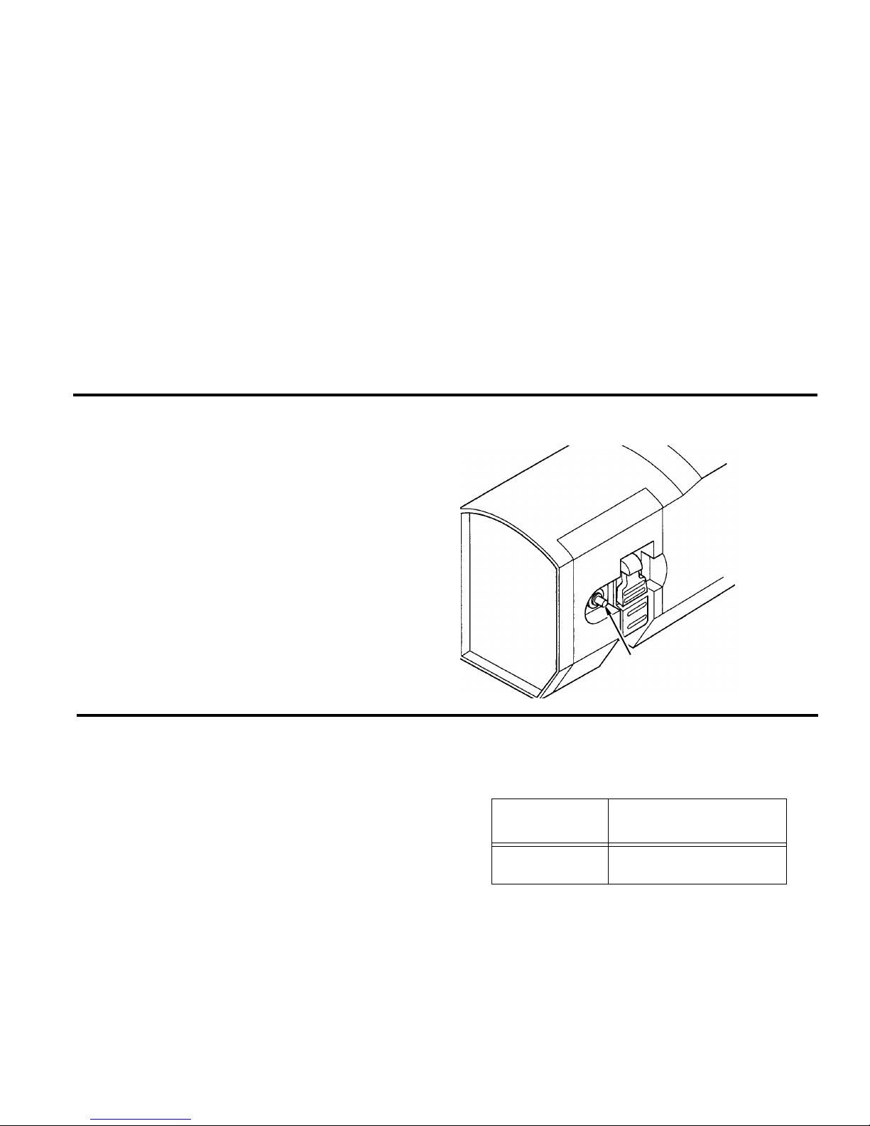
In the event of a malfunction or breakdown, grounding
provides a path of least resistance for electric current to
reduce the risk of electric shock. This tool is equipped
with an electric cord having an equipment grounding con-
ductor and a grounding plug, as shown. The plug must be
plugged into a matching outlet that is properly installed
and grounded in accordance with all local codes and
ordinances.
Do not modify the plug provided. If it will not fit the outlet,
have the proper outlet installed by a qualified electrician.
A temporary adapter may be used to connect this plug to
a 2-pole outlet, as shown, if a properly grounded outlet is
not available. This temporary adapter should be used
only until a properly grounded outlet can be installed by a
qualified electrician. The green colored grounding lug
extension from the adapter must be connected to a per-
manent ground such as a properly grounded outlet box.
Improper connection of the equipment grounding con-
ductor can result in a risk of electric shock. The conduc-
tor with insulation having an outer surface that is green
with or without yellow stripes is the equipment grounding
conductor. If repair or replacement of the electric cord or
plug is necessary, do not connect the equipment-ground-
ing conductor to a live terminal.
If the grounding instructions are not completely under-
stood, or if you are in doubt as to whether the tool is prop-
erly grounded check with a qualified electrician or service
personnel .
WARNING: If not properly grounded, this tool can
cause an electrical shock, particularly when used
in damp locations, in proximity to plumbing, or out
of doors. If an electrical shock occurs there is the
potential of a secondary hazard, such as your
hands contacting the knives.
NOTE: The adapter illustrated is for use only if you already
have a properly grounded 2-prong outlet.
NOTE: In Canada the use of a temporary adapter is not
permitted by the Canadian Electrical Code.
Voltage 110-120
Amperes 15
Hertz (Cycles) 60
Phase Single
Cuts per minute-CPM 18,000
Rotation of Shaft Clockwise
3-Prong
Adapter
2-Prong
Outlet
Make sure this
Is Connected
Ground
Plug
Green to a Known
Grounding Lug
Properly
Grounded
Outlet
3-Prong Plug
Grounding
Prong

7
Motor Safety Protection
IMPORTANT: To reduce the risk of motor damage, this
motor should be blown out or vacuumed periodically to
keep sawdust from interfering with normal motor ventila-
tion.
1. Connect this tool to a power source with the appropri-
ate voltage for your model and a 15-amp branch circuit
with a 15-amp time delay fuse or circuit breaker. Using
the wrong size fuse can damage the motor.
2. If the motor won’t start, turn off the power switch imme-
diately and unplug the tool. Check the cutter head to
make sure it turns freely. If the head is free, try to start
the motor again. If the motor still does not start, refer to
the "Troubleshooting Chart."
3. Fuses may "blow" or circuit breakers may trip fre-
quently if:
a. Motor Is Overloaded-Overloading can occur if you
feed too rapidly or make too many start/stops in a
short time.
b. Line voltages should not be more than 10% above
or below the nameplate voltage. For heavy loads,
however, the voltage at motor terminals must equal
the voltage specified for your model.
c. Improper or dull cutter knives are used.
NOTE: Do not continuously use the thickness planer set
at maximum depth of cut (1/8") and at full 13" width of
cut. Continuous use at maximum cutting capacity will
damage your motor.
4. Most motor troubles may be traced to loose or incor-
rect connections, overload, low voltage (such as small
size wire in the supply circuit) or to overly long supply
circuit wire. Always check the connections, the load
and the supply circuit whenever motor doesn’t work
well. Check wire sizes and length with the Wire Size
Chart.
Thermal Overload Protector
This planer is equipped with a thermal overload protector
device which will automatically “trip” and cause the
planer to shut down if the planer is overheating due to
continuous heavy cutting.
The planer overload protector can only be reset manually
by the user after the planer had been allowed to ade-
quately cool. Allow 15-30 minutes.
Should the overload protector “trip”:
1. Turn switch off.
2. Raise carriage and remove board.
3. Wait 15-30 minutes.
4. Push in on the reset button.
5. If motor has cooled, button will remain in.
Wire Sizes
NOTE: Make sure a proper extension cord is used and it
is in good condition.
The use of any extension cord will cause some loss of
power. To keep this to a minimum and to prevent over-
heating and motor burn-out, use the table below to deter-
mine the minimum wire size (A.W.G.) extension cord.
Use only 3-wire extension cords which have 3-prong
grounding type plugs and 3-pole receptacles which
accept the tools plug.
Thermal Overload Protector
Reset Button
Extension
Cord Length Wire Sizes Required for
(A.W.G.)
0-50 Ft.
50-100 Ft. 14
10

8
Unpacking and Checking Contents
Tools Needed
Tools Required for Alignment
Unpacking
WARNING: To reduce the risk of injury from unex-
pected starting or electrical shock, do not plug the
power cord into a source of power during unpack-
ing and assembly. This cord must remain
unplugged whenever you are working on the thick-
ness planer.
Your thickness planer, is shipped complete in one box.
NOTE: Every RIDGID 13" thickness planer is tested at
the factory to insure its performance. You may see a
small amount of wood dust and chips on your new planer.
WARNING: If any part is missing or damaged, do
not plug the thickness planer in until the missing
or damaged part is correctly replaced. To reduce
the risk of electric shock, use only identical
replacement parts.
Remove the protective oil that is applied to all unpainted
metal surfaces. Use any ordinary household type grease
and spot remover.
WARNING: To reduce the risk of fire or toxic reac-
tion, never use gasoline, naptha or similar highly
volatile solvents.
Apply a coat of paste wax to the table.
Wipe all parts thoroughly with a clean, dry cloth.
WARNING: For your own safety, never connect
plug to power source outlet until all assembly
steps are complete, and you have read and under-
stand the safety and operating instructions.
List of Loose Parts
NOTE: Before beginning assembly, check that all parts
are included. If you are missing any part, do not assem-
ble the thickness planer. Call 1-800-4-RIDGID or E-mail
us at info@ridgidwoodworking.com to get the missing
part. Sometimes small parts can get lost in packaging
material. Do not throw away any packaging until thick-
ness planer is put together. Check packaging for missing
parts before contacting RIDGID.
The following parts are included:
Item Description Qty
A Thickness Planer................................................1
B * Magnetic Knife Handling Tool.............................1
C* Hex “L” Wrench 4mm..........................................1
D * Open End Wrench 8mm/10mm..........................1
E Replacement Blades/Blade Case.......................1
(stored under rear table)
F Owner’s Manual..................................................1
G Bag of Loose Parts.............................................1
(Contains the following items)
H Handle................................................................1
J Screw M5 x 0.8-10..............................................1
K Switch Key..........................................................1
* Supplied in “Tool Box”
Straightedge Wrench 8mm/10mm Hex “L” Wrench 4mm
AB
C
D
F
G
HJ
K
E

9
Assembly
Installing the Handwheel Knob
1. Locate the handwheel knob and screw in the loose
parts bag.
2. Use the hex “L” wrench from the tool box to remove the
screw from the center of the handwheel and remove
the handwheel from the unit.
3. Place the screw through the back of the handwheel
and secure the screw to the knob on the front of the
handwheel.
4. Place the handwheel back on the elevation shaft and
reinstall the screw in the center of the handwheel.
Alignment (Adjustments)
Extension Assembly Alignment
WARNING: To reduce the risk of injury from unex-
pected starting or electrical shock, do not plug the
thickness planer in. The power cord must remain
unplugged whenever you are adjusting or aligning
the thickness planer.
NOTE: Align only one extension at a time. Elevate the
motor enough to give a proper view of the table body and
clearance of the knives.
WARNING: Knives are extremely sharp and could
seriously injure your hands or arms.
1. Place a straight edge across table body and over
infeed extension as shown. Loosen locking nut and
adjust each side of the table until the straightedge
touches the outer edge of table extension. Tighten the
locking nuts.
2. Repeat step 1 for outfeed extension.
Adjusting the Thickness Indicator
The elevation indicator is preset at time of manufacture.
To check indicator select a piece of stock at least 12" long
and 3/4" thick. Set planer to 11/16" and run stock through
planer. Measure wood after planing and if necessary,
loosen screws to adjust elevation indicator to agree with
measurement.
Screw
M5 x 0.8-10
Knob
Planer
Table Body
Straightedge Table
Extension Locking Nut
~

10
Getting to Know Your Thickness Planer
1. Rule. Quickly check the thickness of a workpiece.
2. Carriage Lock. Firmly “locks” the cutter head
assembly to help minimize snipe.
3. Elevation Handwheel. Raises or lowers the cutter
head for the desired cut. Each full revolution of the
elevation handwheel will raise or lower the cutter
head 1/16"
4. Preset Thickness Stops. Limits cutter head to pre-
determined thickness.
5. Elevation Indicator. Indicates the height the cutter
head is from the table.
6. Material Removal Indicator. Indicates how much
material is being removed.
7. Infeed Table. Supports and guides the workpiece at
the start of a cut.
8. On/Off Switch. Lockable, has removable yellow key
which helps to prevent unauthorized use.
9. Thermal Reset Protector. Opens the power line cir-
cuit when the motor temperature exceeds a safe
level, when the motor is overloaded, or when a lower
voltage condition exists.
10. Brush Caps. Provides access to inspect or replace
carbon motor brush.
11. Dust Chute Knobs. Used to attach dust chute and
cover the cutter head.
12. Cord Storage Wrap.
13. Tool Storage. Contains tools and instructions for
changing knives.
14. Outfeed Table. Supports and guides the workpiece
at the end of a cut. Replacement knives stored under
outfeed table.
15. Cutter Head. Rotating cylinder which holds knives.
Located under dust chute.
16. Cutter Head Lock. Red lever, located to the left end
of the cutter head. Automatically activated when dust
chute is removed.
3 Elevation
8On-Off
9Thermal Reset
7Infeed Table
14 Outfeed Table
5Elevation
4Preset Thickness
2Carriage Lock
Switch
Protector
6Material Removal
Indicator
Stops
1Rule
13 Tool Storage
11 Dust Chute
Handwheel
Indicator
Knob(s)
12 Cord Storage
Wrap
10 Brush Cap

11
Safety Instructions for Basic Thickness Planer Operations
Before Using The Thickness Planer
WARNING: To reduce the risk of mistakes that
could cause serious, permanent injury, do not plug
the thickness planer in until the following steps
are completed.
• Completely assemble and align thickness planer. (See
“Assembly” and “Alignment” sections).
• “See Getting To Know Your thickness Planer” section.
• Review and understand all safety instructions and
operating procedures in this manual.
• Review the maintenance methods for this thickness
planer. (See “Maintenance” Section).
Before Each Use
Inspect your thickness planer.
• Disconnect The thickness planer. To reduce the risk of
injury from accidental starting, unplug the thickness
planer, before changing the setup, changing the blade
or adjusting anything.
Check for Damaged Parts. Check for:
• Proper alignment of moving parts,
• Damaged electric cords,
• Binding of moving parts,
• Broken parts,
• Stable mounting
• Other conditions that may affect the way the thickness
planer works.
Before each use, make sure area under the cutter head
and feed rollers is clear.
If any part of this thickness planer is missing, bent, or bro-
ken in any way, or any electrical parts don’t work, turn the
thickness planer off and unplug it. Replace damaged, miss-
ing, or failed parts before using the thickness planer again.
To reduce possibility of throwing pieces, make sure the
knives are properly installed and the knife lock screws
are tight.
Use sharp knives. Dull or knicked knives tend to “pound”
and chew at the wood, causing kickbacks.
Replace dull or damaged planer knives.
Make sure the deflector or dust collector is in place.
Keep Guards in Place, in working order, and in proper
adjustment.
Maintain Tools With Care. Keep the thickness planer
clean for best and safest performance. Follow instruc-
tions for lubricating. DON’T lubricate any part of the thick-
ness planer while the knives are rotating.
Plan Ahead To Protect Your Eyes, Hands, Face and Ears
Know Your Thickness Planer. Read and understand
the owner’s manual and labels affixed to the tool. Learn
its application and limitations as well as the specific
potential hazards peculiar to this tool.
To reduce the risk of injury from accidental contact with
moving parts, don’t do layout, assembly, or setup work on
the thickness planer while any parts are moving.
Reduce The Risk Of Accidental Starting. Make sure
switch is “OFF” before plugging thickness planer into a
power outlet.
Plan your work.
Dress For Safety
.Any power tool can throw foreign objects into the eyes.
This can result in permanent eye damage. Wear safety
goggles (not glasses) that comply with ANSI Z87.1 (or in
Canada CSA Z94-3-M88) shown on package. Everyday
eyeglasses have only impact resistant lenses. They are
not safety glasses. Safety goggles are available at many
local retail stores. Glasses or goggles not in compliance
with ANSI or CSA could seriously hurt you when they
break.
• Do not wear loose clothing, gloves, neckties or jewelry
(rings, wrist watches). They can get caught and draw
you into moving parts.
• Wear nonslip footwear.
• Tie back long hair.
• Roll long sleeves above the elbow.
• Noise levels vary widely. To reduce the risk of possible
hearing damage, wear ear plugs or muffs when using
thickness planer for hours at a time.
• For dusty operations, wear a dust mask along with
safety goggles.
Keep hands at least 20cm (8") from the outfeed. Don’t
grip board tightly or pull board. A sudden kickback could
pull hand into cutters.
Keep hands away from moving parts.

12
Safety Instructions for Basic Thickness Planer Operations
(Continued)
Inspect Your Workpiece
• Make sure there are no nails or foreign objects in the
part of the workpiece to be planed.
• Use quality lumber. Knives last longer and cuts go
smoother on good wood.
• Do not plane undersized wood. Boards which are too
thin or too short could split while being planed.
• Plane boards (12”) 30cm or longer only. Short boards
can jam or split and cause dangerous kickbacks.
• Use for solid wood and wood products only. Do not
plane metals, plastics or laminated materials.
Whenever Thickness Planer Is Running
WARNING: Don’t allow familiarity (gained from fre-
quent use of your thickness planer) to cause a
careless mistake. A careless fraction of a second
is enough to cause a severe injury.
Before starting to plane a board, watch the thickness
planer while it runs. If it makes an unfamiliar noise or
vibrates a lot, stop immediately. Turn the thickness planer
off. Unplug the thickness planer. Do not restart until find-
ing and correcting the problem.
Plan the way you will hold the workpiece from start to
finish:
•Avoid awkward operations and hand positions where
a sudden slip could cause fingers or hand to move into
the knives.
•Don’t Overreach. Keep good footing and balance.
•Do not force the cut. Slowing or stalling the motor will
overheat it. Allow the automatic feed to function prop-
erly.
•Support workpiece. Do not allow the board to hang
from the planer.
•Never use another person as a substitute for a table
extension, or as additional support for a workpiece that
is longer than the basic thickness planer table or to
help feed, support or pull the workpiece.
Take Precautions Against Kickback. Do not permit
anyone to stand or cross in line with the path of the board
through the thickness planer. A kickback or thrown debris
will travel in this direction.
Keep Children Away. Keep all visitors a safe distance
from the thickness planer. Make sure bystanders are
clear of the thickness planer and workpiece.
Let the blade reach full speed before planing.
Turn switch off and unplug tool before inspecting, adjust-
ing or repairing the planer.
Before freeing jammed material:
• Turn switch “OFF”.
• Wait for all moving parts to stop.
• Unplug the thickness planer.
Basic Thickness Planer Operations
Before You Begin
1. Locate the planer where it is intended to be used. Take
into consideration the length of wood you would nor-
mally plane allowing ample room for infeed and out-
feed operations.
CAUTION: Before turning switch on make sure the
dust chute is correctly installed. The ON-OFF
switch has a locking feature. This feature is
intended to prevent unauthorized use by children
and others.
2. Locate the yellow On-OFF switch key from parts bag.
Insert into the switch.
3. To turn planer on, stand to either side of the planer,
never in line with the opening. Insert finger under the
switch and lift key up.
4.To turn planer off push key down. Never leave the
planer until the cutting head has come to a complete
stop.
5. To lock switch in “OFF” position simply remove the key
when in the off position. Always lock the switch “OFF”
when planer is not in use. Remove key and keep it in a
safe place. Also, in the event of power failure (all of
your lights go out) turn switch off, lock it by removing
the key. This will prevent the planer from starting up
again when the power comes back on.
6. Refer to “Thermal Overload Protection” section for
proper use.
Thermal Overload Protector
Reset Button
Yellow
On-Off
Switch Key

13
Reduce Damage To Knives
The thickness planer is a precision wood working
machine and should be used on quality lumber.
Do not plane dirty boards, dirt and small stones are abra-
sive and will wear the blade.
Remove nails and staples. The planer should only cut
wood.
Avoid Knots. Heavy cross grain makes the knots hard,
also, they can come loose and jam the blade.
CAUTION: Any particle that may encounter the
planer knives may be thrown from the planer creat-
ing the risk of severe injury.
Carriage Lock Adjustment
The carriage lock is preadjusted at the factory. If the car-
riage lock lever does not tighten when moved to the lock
position, follow the steps below to adjust.
1. Remove the switch key and unplug the unit from the
wall outlet.
2. Remove the top cover for visibility.
3. Use the hex wrench provided and remove the screw in
the center of the handwheel. Note the position of the
carriage lock lever.
4. Pull the carriage lock lever straight out. This will disen-
gage the carriage lock lever from the mating lock nut.
5. Slightly rotate the carriage lock lever counterclockwise
and reengage the carriage lock lever teeth onto the
lock nut.
Example: If your carriage lock is at a 2 o’clock position
before adjustment, move the lever counterclockwise to
a 1 o’clock position.
6. Turn the lock lever clockwise to the lock position to
assure it is tightening (force to the push the lever is
increasing). Then turn the lever counterclockwise to
the unlock position to assure it becomes very loose in
the unlocked position. If the lock lever is not tightening
in the lock position then repeat steps 5 & 6.
7. Replace the handwheel, secure the screw with the hex
wrench and reinstall the top cover.
Preparing the Work
The thickness planer works best when the lumber has at
least one flat surface.
Use a hand plane or jointer to define a flat surface.
Twisted or severely warped boards can jam the planer,
rip lumber in half to reduce the magnitude of the warp.
The work should be fed with the grain, sometimes the
grain will switch directions in the middle of the cut. If pos-
sible, cut the board in the middle before planing so the
grain direction is correct.
CAUTION: Do not plane a board which is less than
12" long, the force of the cut could split the board
and cause a kickback.
Carriage Lock
The carriage lock (see “Getting To Know Your Thickness
Planer” section) helps to minimize “snipe” by locking the
cutter head position. Snipe is a change in thickness at
either end of the board, caused by an uneven force on
the cutter head when work is entering or leaving the
planer.
Pushing the carriage lock to the left will release the cutter
head assembly. Set planer to the correct thickness (see
below) and then push the carriage lock to the right. This
will lock the cutter head assembly in place and help to
minimize snipe.
A snipe may occur when boards are not supported prop-
erly (see “Extension Assembly Alignment” section).
In a few instances it is impossible to eliminate “snipe”. A
slight snipe may still be noticed. Snipe is more apparent
when deeper cuts are being taken. To avoid snipe when planing more than one board of the
same thickness, butt the boards together end to end so
they follow each other closely through the planer.

14
Basic Thickness Planer Operations (continued)
Elevation Handwheel
WARNING: To reduce the risk of electrical shock,
unwrap cord from cord storage before raising or
lowering carriage.
Turn the elevation handwheel (see “Getting to Know Your
Thickness Planer” section), to set the planer for the cor-
rect depth of cut. The surface the planer will produce will
be smoother if a shallower depth of cut is used. Each full
revolution of the elevation handwheel will raise or lower
the cutter head 1/16".
Feeding the Work
The feed rate refers to the rate at which the lumber trav-
els through the planer.
The planer feed is automatic, it will vary slightly depend-
ing on the type of wood cut and depth of cut.
The operator is responsible for aligning the work so it will
feed properly.
Stand to one side of the planer infeed table.
Lift the work to the infeed extension by grasping the
edges of the board at approximately the middle of the
length.
Boards longer than 24" should have additional support
from free standing material stands.
Rest the board end on the infeed support extension and
direct the board into the planer.
Push slightly on the board and allow the automatic feed
to take the board. Release the board and allow the auto-
matic feed to function properly. Do not push or pull on the
workpiece.
CAUTION: Do not stand directly in line with the
front or rear of the planer, when an object is thrown
from the planer it will travel in this direction.
Move to the rear and receive the planed lumber by grasp-
ing it in the same manner as it was fed.
Do not grasp any portion of the board which has not gone
past the outfeed extension.
Repeat this operation on all the boards which need to be
the same thickness.
NOTE: An assistant must follow the same precaution as
the operator.
The surface that the planer will produce will be smoother
if a shallower depth of cut is used. See “Material Removal
Indicator”.
Feed the work in the direction of the grain. Wood fed
against the grain may result in a chipped splintered sur-
face. If this occurs try feeding the other end of the board
in first.
Material Removal Indicator
Indicates the amount of material being removed on each
pass through the planer. Up to 1/8" max. Make sure the
workpiece is under the Material Removal Indicator label
on the front of the tool.
Recommended maximum depth of cut per pass through
planer:
• 1/8" for material 0-6" in width
• 1/16" for material 6-13" in width
NOTE: Do not continuously use the thickness planer set
at maximum depth of cut (1/8") and at full 13" width of
cut. Continuous use at maximum cutting capacity will
damage your motor.
Preset Thickness Stops (Repeat-A-Cut)
These stops are for repetitive planing to preset thickness.
Planing a workpiece to one of these common thick-
nesses can be easily accomplished:
1. Raise carriage to greater than 1-3/4".
2. Slide the knob to the desired thickness setting.
3. Turn the elevation handle until the carriage contacts
the thickness stop.
4. Lock the carriage lock.
5. Plane the workpiece and check the thickness. If the
thickness is incorrect follow the adjustment steps
below.

15
Thickness Stop (Repeat-A-Cut) Adjustment
1. Pull the Repeat-A-Cut knob straight out to remove.
2. Remove the screw on the right side of the Repeat-A-
Cut scale and remove the cover.
3. Measure the height from the base to the cutter head
knife tip. This can be done with a scrap piece of board
— 1-1/2" for example.
4. Use the elevation handwheel to adjust the height to the
known thickness piece of scrap, then remove the piece
of scrap without moving the handwheel.
5. Make sure the Repeat-A-Cut is on the 1-1/2" setting
and loosen the lock nut on the adjustment bolt. Adjust
the bolt to come in full contact with the step block and
tighten the lock nut.
6. Replace the Repeat-A-Cut cover and secure it with the
screw.
7. Replace the knob.
8. Plane a workpiece and check its thickness. Repeat
procedure, if necessary.
Checking for Worn Knives
The condition of knives will affect the precision of the cut.
Observe the quality of the cut the planer produces to
check the condition of the knives.
Dull knives will tear, rather than sever wood fibers, and
produce a fuzzy appearance.
A raised ridge will occur when dull knives pound on wood
that has a varying density.
If a raised ridge is produced running the length of the
workpiece, the knives have been nicked. If the nick is
small, shift one knife to the right and the other to the left.
(see “Replacing Knives” section).
For knives replacement and installation refer to “Replac-
ing Knives” section.
Maintenance
The planer will operate best if it is kept in good condition.
Keep the unit adjusted as described in the “Operation”
section. Also, the knives must be kept clean and sharp to
ensure the quality of cut and efficiency of operation.
Knives are “double edged”. When one side becomes dull
they may be turned over and the opposite edge used.
WARNING: To reduce the risk of injury from unex-
pected starting or electrical shock. Make certain
that the unit is disconnected from the power
source, before attempting to service, or remove
any component.
Lubrication
Motor and cutter head bearings are sealed and need no
lubrication. Height adjustment guides and elevation
screws should be cleaned of debris and greased when
needed.
Occasionally apply a few drops of light machine oil to the
four support rods to keep the carriage sliding smooth.
Cleaning the Knives
Gum and pitch will collect on knives and cause excess
friction when working. Knives will overheat and wear at
an accelerated rate. Remove knives and clean with a
gum and pitch remover to keep knives clean.
Cleaning The Feed Rollers
Excessive gum, pitch and sawdust can reduce friction of
the rubber rollers. Use alcohol to wipe the rollers.
Motor Ventilation
Check the motor vents periodically while planing and
clear away any sawdust to avoid motor heating.
Changing Brushes
WARNING: To reduce the risk of electrical shock,
fire or injury, use only parts identical to those iden-
tified in the parts list. Reassemble exactly as origi-
nal assembly to reduce the risk of electrical
hazards.
The carbon brushes furnished will last approximately 50
hours of running time or 10,000 on/off cycles. Replace
both carbon brushes when either brush has less than 1/4"
length of carbon remaining. To inspect or replace first
unplug the planer. Then turn the brush caps counterclock-
wise to remove. To reassemble reverse the procedure.
Tighten the brush caps snugly but do not overtighten.
Nut
Bolt

16
Maintenance (continued)
Replacing Knives
Your thickness planer is supplied with double edged
knives. Knives should be replaced or turned 180° to the
unused edges whenever they become dull or nicked.
Keeping a spare set of knives on hand is recommended.
Knives should always be replaced as a matched set.
CAUTION: Exposed knives are sharp and could
injure you. To reduce the possibility of injury pro-
tect your hands with gloves or shop rag and use
the knife tool when removing or installing knives.
1. Be sure the switch key is removed and the unit is
unplugged from the wall receptacle.
2. For easier access to the cutter head/knife assembly
remove the upper cover. See illustration.
3. Loosen the two dust chute knobs and remove the
dust chute.
NOTE: When dust chute is removed the cutter head
lock will engage when the head is rotated. Do not
operate thickness planer without the dust chute in
place, or your planer will be damaged
4. Rotate the cutter head until the lock engages. This
will correctly position a knife and its seven knife lock
screws.
WARNING: To reduce the risk of injury from acci-
dental contact with the exposed knife, when turn-
ing the knife lock screws, lay a folded shop rag
over the knife or wear a glove.
5. Carefully loosen all seven knife locking screws.
NOTE: Move wrench left to right to loosen screws.
6. Use the notched end of the Magnetic Knife Handling
Tool to remove the knife by hooking the notch over
the end of the knife and pulling straight out.
7. Use the magnet on the Magnetic Knife Handling Tool
to help remove the knife.
8. If you are changing to the second edge of the knife,
rotate the knife “end for end” keeping the same flat
side down. This will correctly position the knife to
reinstall. Look closely at the cutter head side view
making sure the knife is installed as pictured. Knives
should be cleaned of gum and pitch before reinstall-
ing.
WARNING: To reduce the risk of thrown blades and
other cutter head parts make sure the knife lock
bar containing the seven knife lock screws is posi-
tioned as shown in the cutter head side view pic-
ture.
9. Push the installed knife in firmly. Visually check that
the knife edge is parallel to the cutter head slot.
10. Tighten the seven (7) knife locking screws.
NOTE: Move wrench right to left to tighten.
11. To rotate the cutter head to the next knife, release the
cutter head lock. Hold down on the red lock lever
located on the left side and rotate the cutter head.
12. Release the red lock lever and continue to rotate the
cutter head until it locks. This should correctly posi-
tion the second knife.
13. Repeat procedures 5 through 10 for the second knife.
14. Check that all knife lock screws are tight and reinstall
the dust chute.
Accessories
Do not use any accessory unless you have received and
read complete instructions for its use. Power Tool Universal Legset ...............................AC9910
Dust Collector......................................................AC8640
Replacement Knives ...........................................AC8630
Knife Lock Screws Knife Lock Bar

17
Wiring Diagram
Troubleshooting
Problem Possible Cause Remedy
Snipe
(Gouging at ends of
board)
1. Dull knives
2. Inadequate support of long boards
3. Lumber not butted properly
4. Extensions misaligned
1. Replace knives per instructions (See
“Replacing Knives” section)
2. Support long boards
3. Butt end to end each piece of stock as
boards pass through planer
4. Adjust extension supports
Fuzzy Grain 1. Planing wood with a high moisture
content 1. Remove high moisture content from wood by
drying
Torn Grain 1. Too heavy a cut
2. Knives cutting against grain
3. Dull knives
1. Review “Depth of Cut” section
2. Review “Feeding the Work” section
3. Replace knives per instructions
Rough Raised Grain 1. Dull knives
2. Too heavy a cut
3. Moisture content too high
1. Replace knives per instructions
2. Review “Depth of Cut”
3. Dry the wood or use dried wood
Uneven Depth Cut
Side to Side 1. Blade projection not uniform 1. Check that end of knife is fully seated in the
cutter head.
Cutter head Eleva-
tion Adjusts with Dif-
ficulty
1. Elevation screws dirty
2. Gears or screws worn
3. Friction between casing and covers
1. Clean and lubricate elevation screws
2. Replace
3. Clean, lubricate
Board Thickness
Does Not Match
Depth of Cut Scale
1. Indicator not set correctly
2. Knife projection incorrect 1. Adjust indicator/securely tighten
2. Set knife projection correctly (See “Replac-
ing Knives” section).
Chain Jumping 1. Sprockets worn
2. Chain worn 1. Replace sprockets
2. Replace chain
Motor does not start 1. Switch malfunction
2. Overload protector tripped
3. Supply fuse opens
4. Brushes worn
5. Other
1. Have a qualified electrician replace the ON/
OFF switch.
2. Turn power switch off. When planer tempera-
ture adequately cools (allow 15-30 minutes)
press overload protector reset button.
3. Replace fuse with a 15 amp time delay fuse,
or circuit breaker.
4. See “Maintenance” section, ”Changing
Brushes
5. Get authorized service.
Dust chute is
blocked 1. Build up of resin under dust chute
2. Large debris 1. Clean dust chute and exhaust area.
2. Clear debris.
Black
White
Green
Power Cord
Switch
Over Load
Grounding Wire
Motor Lead
Motor Lead Motor

18
Repair Parts
Parts List for 13" Thickness Planer
Model No. TP13000
RIDGID parts are available on-line at www.ridgidparts.com
Figure 1
1
23
4
5
6
10
13
14 15
7
8
911
10
12
23
24
25
26
27
28
29
31 32
33
34
35
36
37
38
39
40 41
4243
4445
46 47
48
49
50 51
52 53 54
55
58
59
60
61
62
56
65
66
67
68
69
70 7172
73
74
75
76
77
78
79
80 81 82 83
84
85
86
88
89
90
93
16 1718
19 21
22
30
50
63
64
87
92 91
10
27
37
28
57
18
2835
57
18
94

19
Repair Parts
Parts List for 13" Thickness Planer
Model No. TP13000
RIDGID parts are available on-line at www.ridgidparts.com
Figure 1
Always order by Part Number - Not by Key Number
* Standard Hardware Item - May be purchased locally.
† These replacement parts are available where you purchased your Planer.
Key
No Part No. Description
1
2
3
4
5
6
7
8
9
10
11
12
13
14
15
16
17
18
19
20
21
22
23
24
25
26
27
28
29
30
31
32
33
34
35
36
37
38
39
40
41
42
43
44
45
46
47
48
820380-4
827681
827713
827841
827682
827741
820632-4
827769
827720
*
827717
827719
827726
827766
827724
827754
*
*
827723
827699
827716
*
827695
827753
827926
*
*
827697
827932
827930
827931
827750
827770
827759
827768
*
827704
827767
827738
827678
827725
827737
827751
*
AC8630
827711
827785
Scr Hex Soc Butt Hd M6 x 1.0-16
Cap Left
Scale Length
Cover Upper
Cap Right
Pad Upper
Ring Retaining E15
Worm Gear L.H.
Plate Lock Left
Scr Hex Soc Cap M5 x 0.8-12
Sleeve
Plate Lock Right
Shaft Transmission
Washer 21.5 x 24 x 1
Nut Lock M17 x 2.0
Support
Washer 12 x 16 x 1
Scr Soc Set Cup Pt M5 x 0.8-8
Worm Elevation
Handle
Knob Snipe
Scr Hex Soc Cap M5 x 0.8-10
Chute Dust
Knob Chute
Cover Shroud
Scr Pan Hd M4 x 0.75-6
Washer 4.2 x 10 x 0.9
Manifold Air
Gasket Rear
Gasket Right
Gasket Left
Cover
Worm Gear R.H.
Bushing 4.2 x 11 x 3
Screw Elevating R.H.
Scr Pan Hd M5 x 0.8-6
Plate Dust Chute
Clamp Cord
Spring Coil 9.14x44.45x0.8
Frame Upper
Block Support
Spacer Cutter head Lock
Lock Cutter head
Scr Pan Hd M5 x 0.8-12
† Knife Planer
Bar Knife Lock
Screw Knife Lock
Key
No Part No. Description
49
50
51
52
53
54
55
56
57
58
59
60
61
62
63
64
65
66
67
68
69
70
71
72
73
74
75
76
77
78
79
80
81
82
83
84
85
86
87
88
89
90
91
92
93
94
*
827714
*
827787
827793
827788
827798
827786
820722-5
827680
813249-76
*
*
827729
827817
827739
820401-2
827733
827734
827746
*
827701
827732
*
*
*
827783
827784
827782
827776
827779
827778
827777
827780
827781
827775
820722-21
827774
*
*
*
827773
827772
827794
817453-4
SP6230
Key 5 x12mm
Collar Knife
Scr Hex Soc Cap M4 x 0.75-8
Pulley Cutter head
Belt Drive
Nut Hex M6 x 2.0 L.H.
Pulley Motor
Retainer Bearing
Bearing Ball 6203ZZ
Head Cutter (Includes Collar knife,
Retainer Bearing, Bearing Ball and
Gear Pinion)
Pin Spring 3 x 8mm
Screw Hex Hd M5 x 0.8-26
Nut Hex M5 x 0.8
Rod Step
Nut Special M10 x 1.5
Indicator Depth
Scr Pan Hd M3 x 0.5-16
Rod Pointer Elevating
Spring Coil 8.5X19X0.8
Cover Pointer
Scr Pan Cr M4 x 0.75-10
Housing Pointer
Pointer
Nut M4 x 0.75
Lockwasher Ext Tooth M5
Scr Pan Hd TY TT M5 x 0.8-8
Cover Gear Box
Gear Pinion
Cover Gearbox Inside
Bushing Gear
Gear Large
Gear Intermediate
Gear Small
Spacer Undercut
Spacer 9 x 20 x 5.5
Shaft Gear
Bearing Ball 6002ZZ
Cover Gearbox Outside
Scr Hex Soc Cap M5 x 0.8-25
Scr Hex Soc Cap M5 x 0.8-35
Scr Hex Soc Cap M5 x 0.8-30
Spacer 15 x 20 x 7
Sprocket
Chain
Ring Retaining Ext STW15
Owners Manual

20
Repair Parts
Parts List for 13" Thickness Planer
Model No. TP13000
RIDGID parts are available on-line at www.ridgidparts.com
Figure 2
123
4
5
67
8
9
10
11
12
13
14 10 15
16
17 19
20
21 2223 24
25
26
27
28
29
30
31
32
4
See Figure 3
34
35 36
37
28
38
39
40
41
42
43
45
46
47
48
49
50
51
52
53
54
55
56
12
2
6
5
8
5
5
9
10
39
40
44
57
58
59
18
41
33
51
Table of contents
Other RIDGID Planer manuals

RIDGID
RIDGID R4330 User manual

RIDGID
RIDGID TP1300 User manual

RIDGID
RIDGID R8481 User manual

RIDGID
RIDGID JP06101 User manual

RIDGID
RIDGID R4331 User manual

RIDGID
RIDGID JP06101 User manual

RIDGID
RIDGID R848 User manual

RIDGID
RIDGID R4331 User manual

RIDGID
RIDGID R848 User manual

RIDGID
RIDGID TP1300 User manual