RIDGID TP1300 User manual

23(5$725·60$18$/
WARNING: To reduce the risk of
injury, the user must read and
understand the operator’s manual
before using this product.
SAVE THIS MANUAL FOR
FUTURE REFERENCE
µ7+,&.1(66
3/$1(5
Part No. SP6452 Printed in Taiwan
73

2
Table of Contents
Section Page
Table of Contents ..................................2
Safety Instructions for
Thickness Planer ............................... 3
Safety Symbols ...................................... 3
Before Using The Thickness Planer ...3
When Installing Or Moving The
Thickness Planer ............................... 4
Before Each Use .................................... 5
To Reduce The Risk Of Injury From
Jams, Slips Or Thrown Pieces ..........5
Plan Ahead To Protect Your Eyes,
Hands, Face and Ears .......................5
Inspect Your Workpiece ...................... 6
Whenever Thickness Planer Is
Running .............................................6
Before Leaving The
Thickness Planer ............................... 7
Glossary of Terms for Woodworking ..... 7
Motor Specifications and Electrical
Requirements .................................... 8
Power Supply and Motor
Specifications .................................... 8
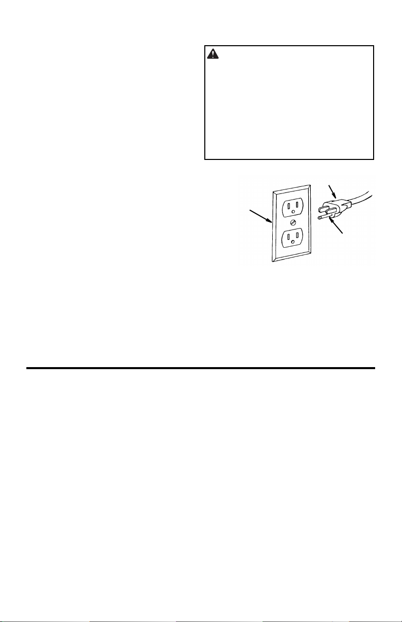
General Electrical Connections .......... 8
110-120 Volt, 60 Hz. Tool Information 8
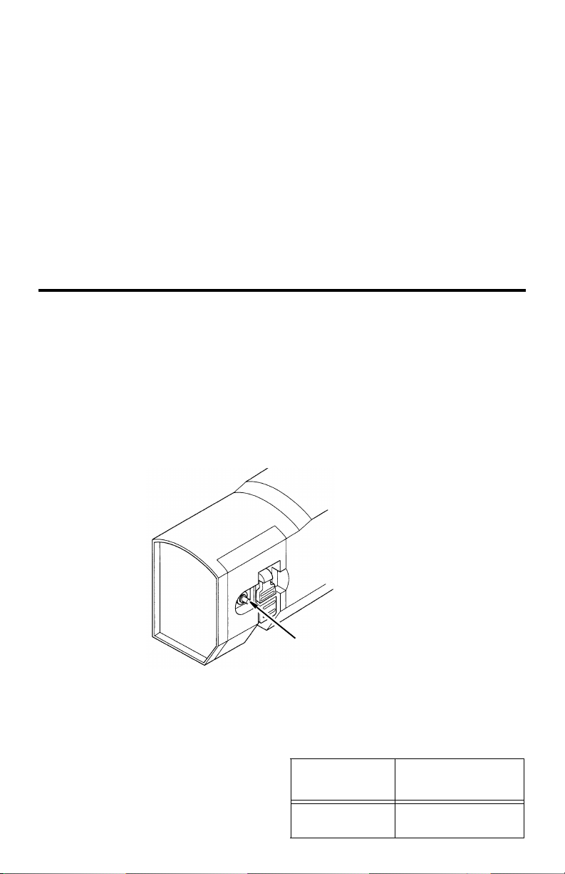
Motor Safety Protection ...................... 9
Thermal Overload Protector ............. 10
Wire Sizes .........................................10
Unpacking and Checking Contents .....11
Tools Needed ................................... 11
Unpacking ......................................... 11
List of Loose Parts ............................ 11
Assembling Legset ..............................12
Assembling Upper and
Lower Legs ...................................... 13
Assembling Lower Stiffeners ............13
Assembling Upper Stiffeners ............14
Mounting The Thickness Planer .......... 15
Mounting on Legset ..........................15
Mounting Thickness Planer on
Supplied Legset ...............................15
Mounting Thickness Planer on
Other Legsets or Work Benches ..... 15
Section Page
Portable Applications ........................ 15
Work Bench Applications .................. 15
Installing the Handwheel Knob ............ 16
Alignment (Adjustments) ..................... 16
Extension Assembly Alignment ........ 16
Adjusting the Thickness Indicator ..... 16
Getting to Know Your
Thickness Planer ............................. 17
Safety Instructions for Basic Thickness
Planer Operations ............................... 18
Before Using The Thickness Planer . 18
Before Each Use .............................. 18
Plan Ahead To Protect Your Eyes,
Hands, Face and Ears .................... 18
Inspect Your Workpiece ................... 19
Whenever Thickness Planer Is
Running ........................................... 19
Basic Thickness Planer Operations .... 20
Before You Begin ............................. 20
Reduce Damage To Knives .............. 21
Preparing the Work ........................... 21
Carriage Lock ................................... 21
Carriage Lock Adjustment ................ 22
Elevation Handwheel ........................ 22
Feeding the Work ............................. 22
Material Removal Indicator ............... 23
Preset Thickness Stops
(Repeat-A-Cut) ................................ 23
Thickness Stop (Repeat-A-Cut)
Adjustment ...................................... 23
Checking for Worn Knives ................ 24
Maintenance ........................................ 24
Lubrication ........................................ 24
Cleaning the Knives .......................... 24
Cleaning The Feed Rollers ............... 24
Motor Ventilation ............................... 24
Changing Brushes ............................ 25
Replacing Knives .............................. 25
Accessories ......................................... 26
Wiring Diagram .................................... 26
Troubleshooting ................................... 27
Repair Parts ........................................ 28
Notes ................................................... 34

3
Safety Instructions for Thickness Planer
The purpose of safety symbols is to
attract your attention to possible
dangers. The safety symbols, and the
explanations with them, deserve your
careful attention and understanding.
The safety warnings do not by
themselves eliminate any danger.
The instructions or warnings they give
are not substitutes for proper accident
prevention measures.
Safety Symbols
DANGER: indicates an imminently
hazardous situation which, if not
avoided, will result in death or serious
injury.
WARNING: indicates a potentially
hazardous situation which, if not
avoided, could result in death or seri-
ous injury.
CAUTION: indicates a potentially
hazardous situation which, if not
avoided, may result in minor or mod-
erate injury. It may also be used to
alert against unsafe practices that
may cause property damage.
Before Using The Thickness Planer
WARNING: Some dust created
by power sanding, sawing, grinding,
drilling, and other construction
activities contains chemicals known
(to the State of California) to cause
cancer, birth defects or other repro-
ductive harm. Some examples of
these chemicals are:
• Lead from lead-bases paints,
• Crystalline silica from bricks and
cement and other masonry prod-
ucts, and
• Arsenic and chromium from
chemically-treated lumber.
Your risk from these exposures var-
ies, depending on how often you do
this type of work. To reduce your
exposure to these chemicals: work
in a well ventilated area, and work
with approved safety equipment,
such as those dust masks that are
specially designed to filter out
microscopic particles.
WARNING: To reduce the risk
of mistakes that could cause seri-
ous, permanent injury, do not plug
the thickness planer in until the fol-
lowing steps have been satisfacto-
rily completed.
• Completely assemble and align
thickness planer. (See “Assembly”
and “Alignment” sections.)
• Learn the use and function of the
on-off switch, cutter guard, elevation
hand wheel, outfeed table and
infeed table (see “Getting to Know
Your Thickness Planer” section
within.)
• Review and understand all safety
instructions and operating proce-
dures in this manual.
• Review the maintenance methods
for this thickness planer. (See
“Maintenance” section within).
WARNING: Do not attempt to use the tool until you have read thorough-
ly and understand completely the operator’s manual. Pay close attention to
the safety rules, including Dangers, Warnings, and Cautions. If you use this
tool properly and only for what it is intended, you will enjoy years of safe, re-
liable service.

4
Safety Instructions for Thickness Planer (continued)
• Find and Read the following labels on the thickness planer:
When Installing Or Moving The Thickness Planer
• Before moving the thickness planer,
turn off and unplug the power cord.
• To reduce the risk of back injury, get
help when you need to lift the thick-
ness planer.
Avoid Dangerous Environment.
• Use the thickness planer in a dry,
indoor place protected from rain.
• Keep work area well lighted.
• Place the thickness planer so neither
the user nor bystanders are forced to
stand in line with the wood. Thrown
debris could injure people in its path.
• Place the thickness planer where there
is room for moving the workpiece
through the entire cut.
To reduce the risk of injury from
unexpected thickness planer
movement:
• Put the thickness planer on a firm
level surface where there is plenty
of room for handling and properly
supporting the workpiece.
• Support the thickness planer so the
tables are level and the thickness
planer does not rock.
• Bolt or clamp the thickness planer to
the table/bench if it tends to slip,
walk, slide or tip over during work
such as planing long, heavy boards.
•Never Stand On Tool. Serious
injury could occur if the tool tips or
you accidentally hit the cutting tool.
Do not store anything above or near
the tool where anyone might stand
on the tool to reach them.
To reduce the risk of injury or
death from electrical shock:
Make sure your fingers do not touch
the plug’s metal prongs when plug-
ging or unplugging the thickness
planer.

5
Before Each Use
Inspect your thickness planer.
•Disconnect The Thickness Planer
to reduce the risk of injury from acci-
dental starting before changing the
setup, changing the blade or adjust-
ing anything.
Check For Damaged Parts. Check
for:
• Proper alignment of moving parts,
• Damaged electric cords,
• Binding of moving parts,
• Broken parts,
• Stable mounting,
• Other conditions that may affect the
way the thickness planer works.
Before each use, make sure area
under the cutter head and feed rollers
is clear.
If any part of this thickness planer is
missing, bent, or broken in any way,
or any electrical parts don’t work, turn
the thickness planer off and unplug it.
Replace damaged, missing, or failed
parts before using the thickness
planer again.
To reduce possibility of thrown
pieces, make sure the knives are
properly installed and the knife lock
screws are tight.
Use sharp knives. Dull or knicked
knives tend to “pound” and chew at
the wood, causing kickbacks.
Replace dull or damaged planer
knives.
Make sure the dust chute is in place.
Keep Guards In Place, in working
order, and in proper adjustment.
Maintain Tools With Care. Keep the
thickness planer clean for best and
safest performance. (See “Mainte-
nance” section) DON’T lubricate any
part of the thickness planer while the
knives are rotating.
To Reduce The Risk Of Injury From Jams, Slips Or Thrown Pieces
•Use Only Recommended Acces-
sories. (See “Accessory” section).
Consult this Operator’s manual for
recommended accessories. Follow
the instructions that come with the
accessories. The use of improper
accessories may cause injury to
persons.
•Keep Work Area Clean. Cluttered
areas and benches invite acci-
dents. Floor must not be slippery.
To reduce the risk of burns or other
fire damage, never use the thickness
planer near flammable liquids, vapors
or gases.
Plan Ahead To Protect Your Eyes, Hands, Face and Ears
Know Your Thickness Planer. Read
and understand the operator’s man-
ual and labels affixed to the tool.
Learn its applications and limitations
as well as the specific potential haz-
ards peculiar to this tool.
To reduce the risk of injury from acci-
dental contact with moving parts,
don’t do layout, assembly, or setup
work on the thickness planer while
any parts are moving.
Reduce the Risk of Accidental
Starting. Make sure switch is “OFF”
before plugging thickness planer into
a power outlet.
Plan your work.
Use the right tool. Don’t force planer
to do a job it was not designed to do.
NOTE: Advises you of information or
instructions vital to the operation or
maintenance of the equipment.

6
Safety Instructions for Thickness Planer (continued)
Dress For Safety
Any power tool can throw foreign
objects into the eyes. This can result
in permanent eye damage. Wear
safety goggles (not glasses) that
comply with ANSI Z87.1 (or in Can-
ada CSA Z94.3-99) shown on pack-
age. Everyday eyeglasses have only
impact resistant lenses. They are not
safety glasses. Safety goggles are
available at many local retail stores.
Glasses or goggles
not in compliance
with ANSI or CSA
could seriously hurt
you when they
break.
• Do not wear loose clothing, gloves,
neckties or jewelry (rings, wrist
watches) They can get caught and
draw you into moving parts.
• Wear nonslip footwear.
• Tie back long hair.
• Roll long sleeves above the elbow.
• Noise levels vary widely. To reduce
the risk of possible hearing damage,
wear ear plugs or muffs when using
thickness planer for hours at a time.
• For dusty operations, wear a dust
mask along with safety goggles.
Keep hands at least (8") 20cm from
the outfeed. Don’t grip board tightly or
pull board. A sudden kickback could
pull hand into cutters.
Keep hands away from moving parts.
Inspect Your Workpiece
• Make sure there are no nails or for-
eign objects in the part of the work-
piece to be planed.
• Use quality lumber. Knives last
longer and cuts go smoother on
good wood.
• Do not plane undersized wood.
Boards which are thinner than 1/8"
or shorter than 12" could split while
being planed.
• Plane boards (12”) 30cm or longer
only. Short boards can jam or split
and cause dangerous kickbacks.
• Use for solid wood and wood prod-
ucts only. Do not plane metals, plas-
tics or laminated materials.
Whenever Thickness Planer Is Running
WARNING: Don't allow familiar-
ity (gained from frequent use of
your thickness planer) to cause a
careless mistake. A careless frac-
tion of a second is enough to cause
a severe injury.
Before starting to plane a board,
watch the thickness planer while it
runs. If it makes an unfamiliar noise
or vibrates a lot, stop immediately.
Turn the thickness planer off. Unplug
the thickness planer. Do not restart
until finding and correcting the prob-
lem.
Plan the way you will hold the
workpiece from start to finish:
•Avoid awkward operations and
hand positions where a sudden slip
could cause fingers or hand to move
into the knives.
•Don’t Overreach. Keep good foot-
ing and balance.
•Do not force the cut. Slowing or
stalling the motor will overheat it.
Allow the automatic feed to function
properly.
•Support workpiece. Do not allow
the board to hang from the planer.

7
•Never use another person as a sub-
stitute for a table extension, or as
additional support for a workpiece
that is longer or wider than the basic
thickness planer table or to help
feed, support or pull the workpiece.
Take Precautions Against Kickback.
Do not permit anyone to stand or
cross in line with the path of the board
through the thickness planer. A kick-
back or thrown debris will travel in this
direction.
Keep Children Away. Keep all visi-
tors a safe distance from the thick-
ness planer. Make sure bystanders
are clear of the thickness planer and
workpiece.
Let the blade reach full speed before
planing.
Turn switch off and unplug tool before
inspecting, adjusting or repairing the
planer.
Before freeing jammed material:
• Turn switch “OFF”.
• Wait for all moving parts to stop.
• Unplug the thickness planer.
Before Leaving The Thickness Planer
Never Leave Tool Running Unat-
tended. Turn power off. Wait for all
moving parts to stop.
Make workshop child-proof. Lock
the shop. Remove yellow switch key
and store away from tool. Disconnect
master switches. Store away from
children and others not qualified to
use the tool.
Glossary of Terms for Woodworking
Bed - The combination of infeed and out-
feed table surfaces which support the
workpiece during a cutting operation.
Cutter Head - The cutter head is a rotat-
ing piece with two adjustable knives. The
cutter head removes material from the
workpiece.
Depth of cut - A term used to indicate
how deep into the workpiece the cutter
knives will cut.
Gum - A sticky, sap based residue from
wood products.
Infeed Table - The section of the thick-
ness planer upon which the workpiece is
placed before being pushed into the cutter
head.
Kickback - An uncontrolled grabbing and
throwing of the workpiece back toward the
operator by the rotating cutter head.
Leading End- The end of the workpiece
which is pushed into the cutter head first.
Outfeed Table - The section of a thick-
ness planer which supports the workpiece
after it passes under the cutter head.
The operation of any power tool can result in foreign objects being thrown
into your eyes, which can result in severe eye damage. Before beginning tool
operation, always wear safety goggles of safety glasses with side shields
and a full face shield when needed. We recommend Wide Vision Safety
Mask for use over eyeglasses or standard safety glasses with side shields.
Always wear eye protection which is marked to comply wtih ANSI Z87.1.
WARNING:
Look for this symbol to point out important safety precautions. It
means attention!!! Your safety is involved.
SAVE THESE INSTRUCTIONS

8
Glossary of Terms for Woodworking (continued)
Planing - Removing wood from the wid-
est surface or face of a board so as to
make it flat and smooth.
Resin - A sticky, sap based substance
that has hardened.
Revolutions Per Minute (RPM) - The
number of turns completed by a spinning
object in one minute.
Snipe - The localized variation in work-
piece thickness.
Throw-Back -
Throwing of pieces in a manner similar to
a kickback.
Trailing End
The workpiece end last cut by the knives.
Workpiece
The item on which the cutting operation is
being performed. The surfaces of a work-
piece are commonly referred to as faces,
ends and edges.
Motor Specifications and Electrical Requirements
Power Supply and Motor
Specifications
WARNING: To reduce the risk of
electrical hazards, fire hazards or
damage to the tool, use proper cir-
cuit protection. Your tool is wired at
the factory for operation using the
voltage shown. Connect tool to a
power line with the appropriate volt-
age and a 15-amp branch circuit.
Use a 15-amp time delay type fuse
or circuit breaker. To reduce the risk
of shock or fire, replace power cord
immediately if it is worn, cut, or
damaged in any way.
The A-C motor used on this tool is an uni-
versal non-reversible type, having the fol-
lowing specifications:
General Electrical Connections
DANGER: To reduce the risk of
electrocution:
1. Use only identical replacement
parts when servicing. Servicing
should be performed by a quali-
fied service technician.
2. Do not use in rain or where floor
is wet. This tool is intended for
indoor use only.
WARNING: To reduce the risk
of electrical shock do not permit
fingers to touch the terminals or
plug when installing or removing
the plug to or from the outlet.
If power cord is worn or cut, damaged in
any way, have it replaced immediately.
110-120 Volt, 60 Hz. Tool Information
NOTE: The plug supplied on your tool
may not fit into the outlet you are planning
to use. Your local electrical code may
require slightly different power cord plug
Face
Edge
End
Voltage 110-120
Amperes 15
Hertz (Cycles) 60
Phase Single
Cuts per minute-CPM 18,000
Rotation of Shaft Clockwise

9
connections. If these differences exist
refer to and make the proper adjustments
per your local code before your tool is
plugged in and turned on.
In the event of a malfunction or break-
down, grounding provides a path of least
resistance for electric current to reduce
the risk of electric shock. This tool is
equipped with an electric cord having an
equipment grounding conductor and a
grounding plug, as shown. The plug must
be plugged into a matching outlet that is
properly installed and grounded in accor-
dance with all local codes and ordi-
nances.
Do not modify the plug provided. If it will
not fit the outlet, have the proper outlet
installed by a qualified electrician.
Improper connection of the equipment
grounding conductor can result in a risk of
electric shock. The conductor with insula-
tion having an outer surface that is green
with or without yellow stripes is the equip-
ment grounding conductor. If repair or
replacement of the electric cord or plug is
necessary, do not connect the equipment-
grounding conductor to a live terminal.
If the grounding instructions are not com-
pletely understood, or if you are in doubt
as to whether the tool is properly
grounded check with a qualified electri-
cian or service personnel .
WARNING: If not properly
grounded, this tool can cause an
electrical shock, particularly when
used in damp locations, in proximity
to plumbing, or out of doors. If an
electrical shock occurs there is the
potential of a secondary hazard,
such as your hands contacting the
knives.
Motor Safety Protection
IMPORTANT: To reduce the risk of motor
damage, this motor should be blown out
or vacuumed periodically to keep sawdust
from interfering with normal motor ventila-
tion.
1. Connect this tool to a power source
with the appropriate voltage for your
model and a 15-amp branch circuit with
a 15-amp time delay fuse or circuit
breaker. Using the wrong size fuse can
damage the motor.
2. If the motor won’t start, turn off the
power switch immediately and unplug
the tool. Check the cutter head to make
sure it turns freely. If the head is free,
try to start the motor again. If the motor
still does not start, refer to the "Trouble-
shooting Chart."
Properly
Grounded
3-Prong Plug
Grounding
Prong
3-Prong Outlet

10
Motor Specifications and Electrical Requirements (continued)
3. Fuses may "blow" or circuit breakers
may trip frequently if:
a. Motor Is Overloaded-Overloading
can occur if you feed too rapidly or
make too many start/stops in a short
time.
b. Line voltages should not be more
than 10% above or below the name-
plate voltage. For heavy loads, how-
ever, the voltage at motor terminals
must equal the voltage specified for
your model.
c. Improper or dull cutter knives are
used.
NOTE: Do not continuously use the thick-
ness planer set at maximum depth of cut
(1/8") and at full 13" width of cut. Continu-
ous use at maximum cutting capacity will
damage your motor.
4. Most motor troubles may be traced to
loose or incorrect connections, over-
load, low voltage (such as small size
wire in the supply circuit) or to overly
long supply circuit wire. Always check
the connections, the load and the sup-
ply circuit whenever motor doesn’t work
well. Check wire sizes and length with
the Wire Size Chart.
Thermal Overload Protector
This planer is equipped with a thermal
overload protector device which will auto-
matically “trip” and cause the planer to
shut down if the planer is overheating due
to continuous heavy cutting.
The planer overload protector can only be
reset manually by the user after the
planer had been allowed to adequately
cool. Allow 15-30 minutes.
Should the overload protector “trip”:
1. Turn switch off.
2. Raise carriage and remove board.
3. Wait 15-30 minutes.
4. Push in on the reset button.
5. If motor has cooled, button will remain
in.
Wire Sizes
NOTE: Make sure a proper extension
cord is used and it is in good condition.
The use of any extension cord will cause
some loss of power. To keep this to a min-
imum and to prevent overheating and
motor burn-out, use the table below to
determine the minimum wire size
(A.W.G.) extension cord.
Use only 3-wire extension cords which
have 3-prong grounding type plugs and 3-
pole receptacles which accept the tools
plug.
Thermal Overload Protecto
r
Reset Button
Extension Cord
Length Wire Sizes Required
for (A.W.G.)
0-50 Ft.
50-100 Ft.
14
10

11
Unpacking and Checking Contents
Tools Needed
Tools Required for Alignment
Unpacking
WARNING: To reduce the risk of
injury from unexpected starting or
electrical shock, do not plug the
power cord into a source of power
during unpacking and assembly.
This cord must remain unplugged
whenever you are working on the
thickness planer.
Your thickness planer, is shipped com-
plete in one box.
NOTE: Every RIDGID 13" thickness
planer is tested at the factory to insure its
performance. You may see a small
amount of wood dust and chips on your
new planer.
WARNING: If any part is miss-
ing or damaged, do not plug the
thickness planer in until the missing
or damaged part is correctly
replaced. To reduce the risk of elec-
tric shock, use only identical
replacement parts.
Remove the protective oil that is applied
to all unpainted metal surfaces. Use any
ordinary household type grease and spot
remover.
WARNING: To reduce the risk of
fire or toxic reaction, never use gas-
oline, naptha or similar highly vola-
tile solvents.
Apply a coat of paste wax to the table.
Wipe all parts thoroughly with a clean, dry
cloth.
WARNING: For your own safety,
never connect plug to power source
outlet until all assembly steps are
complete, and you have read and
understand the safety and operat-
ing instructions.
List of Loose Parts
NOTE: Before beginning assembly, check
that all parts are included. If you are miss-
ing any part, do not assemble the thick-
ness planer. Call 1-866-539-1710 to get
the missing part. Sometimes small parts
can get lost in packaging material. Do not
throw away any packaging until thickness
planer is put together. Check packaging
for missing parts before contacting
RIDGID.
Straightedge Wrench 8mm/10mm Hex “L” Wrench 4mm

12
Unpacking and Checking Contents (continued)
The following parts are included:
Item Description Qty
A Thickness Planer ...........................1
B * Magnetic Knife Handling Tool........1
C * Hex “L” Wrench 4mm .................... 1
D * Open End Wrench 8mm/10mm ..... 1
E Replacement Blades/Blade Case .. 1
(stored under rear table)
F Operator’s Manual ......................... 1
G Bag of Loose Parts ........................1
(Contains the following items)
H Handle............................................ 1
Item Description Qty
J Screw M5 x 0.8-10......................... 1
K Switch Key..................................... 1
L Upper Leg...................................... 4
M Lower Leg...................................... 4
N Long Upper Stiffener...................... 2
P Long Lower Stiffener...................... 2
Q Short Upper Stiffener ..................... 2
R Short Lower Stiffener ..................... 2
S Foot ............................................... 4
T Hardware pack, Legset Hardware . 1
* Supplied in “Tool Box”
Assembling Legset
1. Locate the following parts:
4 Lower Legs
4 Upper Legs
2 Long Upper Stiffeners
2 Short Upper Stiffeners
2 Long Lower Stiffeners
2 Short Lower Stiffeners.
2. From the leg set hardware bag find the
following:
4Feet
32 Carriage Bolts M8 x 1.25
32 Hex Flanged Nuts M8 x 1.25
NOTE: Hardware not shown actual size.
AB
C
D
F
G
E
LMNP
QR
S
HJ
K
T
Lower Leg
L
ong Upper
Stiffener Long Lower
Stiffener
Short Lower
Stiffener
Short Upper
Stiffener
Flange Nut
Bolt
Foot
Upper Leg

13
Assembling Upper and Lower Legs
1. Locate the following parts and hard-
ware:
8 Cariage Bolts M8 x 1.25
8 Hex Flanged Nuts M8 x 1.25
4 Upper Legs
4 Lower Legs
4Feet
2. Position the lower leg inside the upper
leg as shown. Place a bolt only through
the bottom hole of the upper leg and
through the bottom hole of the lower
leg. Attach a nut but only finger tighten.
3. Repeat for other three leg assemblies.
4. Asemble foot to bottom of lower leg.
Repeat for other three leg assemblies.
Assembling Lower Stiffeners
1. Locate the following parts and hard-
ware:
8 Carriage Bolts M8 x 1.25
8 Hex Flanged Nuts M8 x 1.25
2 Long Lower Stiffeners
2 Short Lower Stiffeners
Lower Leg
Upper Leg
Hex Flanged Nut
M8 x 1.25
Carriage Bolts
M8 x 1.25
Nu
t
Bottom
Bolt
Lower
Upper Leg
Hole Leg
Bottom
Hole Bolt
Nut
Foot
Hex Flanged Nut
M8 x 1.25
Carriage Bolts
M8 x 1.25
L
ong Lower
Stiffener Short Lowe
r
Stiffener

14
Assembling Legset (continued)
Assembling Lower Stiffeners (cont.)
2. Assemble the lower stiffeners to the
legs as shown. Finger tighten the nuts.
Make sure:
a. The long and short lower stiffeners fit
inside the legs.
b. The short stiffeners must be assem-
bled on opposite sides of the leg set.
(The same for the long stiffeners.).
Assembling Upper Stiffeners
1. Locate the following parts and hard-
ware:
16Carriage Bolts M8 x 1.25
16Hex Flanged Nuts M8 x 1.25
2 Long Upper Stiffeners
2 Short Upper Stiffeners
2. Assemble the upper stiffeners to the
legs as shown. Finger tighten nuts.
Make sure:
a. The long upper stiffeners go over the
short upper stiffeners. Make sure the
stiffeners go inside the legs.
b. The short upper stiffeners go oppo-
site each other, same as the long
upper stiffeners.
c. The planer mounting holes in the top
of the legset are aligned.
3. Go back and tighten all nuts.
Short
Lower
Stiffener
Carriag
e
Bolt
Nut
Hex Flanged Nut
M8 x 1.25
Carriage Bolts
M8 x 1.25
Long Upper Short Upp
er
Stiffener
Stiffener
S
hort Upper
Stiffener
Short
Lower
Stiffener
Carriage
Bolt
N
ut
Long
Lower
Stiffener
Long
Upper
Stiffene
r

15
Mounting Thickness Planer on
Supplied Legset
1. Locate 4 hex screws M8 x 1.25 and the
remaining 4 flange nuts and 4 washers
in parts bag.
2. Position leg set at the desired location .
3. Mount the thickness planer as shown
with provided hardware. Only finger
tighten nuts at this time.
If necessary shift the leg set to adjust for
slightly unlevel floor. Securely tighten all
hardware.
Mounting Thickness Planer on
Other Legsets or Work Benches
Place the planer in the desired location on
either a workbench or other recom-
mended leg set. The base of the planer
has eight mounting holes. Four smaller
holes for “drywall” screws are labeled B.
Four larger holes for bolts are labeled A
(see illustration). Place a bolt through the
larger holes. Attach a washer and nut and
securely tighten.
Portable Applications
To mount the planer to a 3/4” piece of ply-
wood, use 4, 1/4" bolt holes or the 4 dry-
wall screw holes. The mounting board can
then be clamped down to prevent it from
tipping.
Work Bench Applications
Mount as specified in portable applica-
tions. Check for workpiece clearances to
front and rear of planer.
Mounting Board or Work Surface
AB
BA
AB
BA
Mounting The Thickness Planer
Mounting on Legset
WARNING: To reduce the risk of injury from unexpected planer movement:
a. Unplug electric cord.
b. To reduce the risk of back injury, hold the tool close to your body when
lifting. Bend your knees so you can lift with your legs, not your back. Lift
by using the hand-hold areas at each side of the bottom of the base or by
the carrying handles.
c. Place the planer so other people cannot stand behind it. Thrown debris
could injure people in its path.
d. Place the planer on a firm, level surface where there is plenty of room for
handling and properly supporting the workpiece.
e. Bolt or clamp the planer to its support.

16
Installing the Handwheel Knob
1. Locate the handwheel knob and screw
in the loose parts bag.
2. Use the hex “L” wrench from the tool
box to remove the screw from the cen-
ter of the handwheel and remove the
handwheel from the unit.
3. Place the screw through the back of the
handwheel and secure the screw to the
knob on the front of the handwheel.
4. Place the handwheel back on the ele-
vation shaft and reinstall the screw in
the center of the handwheel.
Alignment (Adjustments)
Extension Assembly Alignment
WARNING: To reduce the risk of
injury from unexpected starting or
electrical shock, do not plug the thick-
ness planer in. The power cord must
remain unplugged whenever you are
adjusting or aligning the thickness
planer.
NOTE: Align only one extension at a time.
Elevate the motor enough to give a proper
view of the table body and clearance of
the knives.
WARNING: Knives are
extremely sharp and could seri-
ously injure your hands or arms.
1. Place a straight edge across table body
and over infeed extension as shown.
Loosen locking nut and adjust each
side of the table until the straightedge
touches the outer edge of table exten-
sion. Tighten the locking nuts.
2. Repeat step 1 for outfeed extension.
Adjusting the Thickness Indicator
The elevation indicator is preset at time of
manufacture. To check indicator select a
piece of stock at least 12" long and 3/4"
thick. Set planer to 11/16" and run stock
through planer. Measure wood after plan-
ing and if necessary, loosen screws to
adjust elevation indicator to agree with
measurement.
Screw
M5 x 0.8-10 Knob
Planer
Table Body
Straightedge
Table
Extension
Locking
~
Nut

17
Getting to Know Your Thickness Planer
1. Rule. Quickly check the thickness of a
workpiece.
2. Carriage Lock. Firmly “locks” the cut-
ter head assembly to help minimize
snipe.
3. Elevation Handwheel. Raises or low-
ers the cutter head for the desired cut.
Each full revolution of the elevation
handwheel will raise or lower the cut-
ter head 1/16"
4. Preset Thickness Stops. Limits cut-
ter head to predetermined thickness.
5. Elevation Indicator. Indicates the
height the cutter head is from the
table.
6. Mounting Holes. Reduces the risk of
injury from unexpected planer move-
ment. Smaller holes are for “drywall”
screws, larger holes for bolts, nuts
and washers.
7. Material Removal Indicator. Indi-
cates how much material is being
removed.
8. Infeed Table. Supports and guides
the workpiece at the start of a cut.
9. On/Off Switch. Lockable, has remov-
able yellow key which helps to pre-
vent unauthorized use.
10.Thermal Reset Protector. Opens the
power line circuit when the motor tem-
perature exceeds a safe level, when
the motor is overloaded, or when a
lower voltage condition exists.
11. Brush Caps. Provides access to
inspect or replace carbon motor
brush.
12.Dust Chute Knobs. Used to attach
dust chute and cover the cutter head.
13.Cord Storage Wrap.
14.Tool Storage. Contains tools and
instructions for changing knives.
15.Outfeed Table. Supports and guides
the workpiece at the end of a cut.
Replacement knives stored under out-
feed table.
16.Cutter Head. (Not illustrated) Rotat-
ing cylinder which holds knives.
Located under dust chute.
17.Cutter Head Lock. (Not illustrated)
Red lever, located to the left end of
the cutter head. Automatically acti-
vated when dust chute is removed.
3 Elevation
9On-Off
1
0Thermal Reset
8
Infeed
15 Outfeed
5Elevation
4Preset
2Carriage Lock
Switch
Protector
7Material Removal
Indicator
Stops
1Rule
14 Tool
12 Dust Chute
Handwheel
Indicator
Knob(s)
13
Cord Storag
e
Wrap
11 Brush
6Mounting
Holes
Storage
Table
Table
Cap
Thickness

18
Safety Instructions for Basic Thickness Planer
Operations
Before Using The Thickness Planer
WARNING: To reduce the risk of
mistakes that could cause serious,
permanent injury, do not plug the
thickness planer in until the follow-
ing steps are completed.
• Completely assemble and align
thickness planer. (See “Assembly”
and “Alignment” sections).
• “See Getting To Know Your thick-
ness Planer” section.
• Review and understand all safety
instructions and operating proce-
dures in this manual.
• Review the maintenance methods
for this thickness planer. (See
“Maintenance” Section).
Before Each Use
Inspect your thickness planer.
• Disconnect the thickness planer. To
reduce the risk of injury from acci-
dental starting, unplug the thickness
planer, before changing the setup,
changing the blade or adjusting any-
thing.
Check for Damaged Parts. Check
for:
• Proper alignment of moving parts,
• Damaged electric cords,
• Binding of moving parts,
• Broken parts,
• Stable mounting,
• Other conditions that may affect the
way the thickness planer works.
Before each use, make sure area
under the cutter head and feed rollers
is clear.
If any part of this thickness planer is
missing, bent, or broken in any way,
or any electrical parts don’t work, turn
the thickness planer off and unplug it.
Replace damaged, missing, or failed
parts before using the thickness
planer again.
To reduce possibility of throwing
pieces, make sure the knives are
properly installed and the knife lock
screws are tight.
Use sharp knives. Dull or knicked
knives tend to “pound” and chew at
the wood, causing kickbacks.
Replace dull or damaged planer
knives.
Make sure the deflector or dust col-
lector is in place.
Keep Guards in Place, in working
order, and in proper adjustment.
Maintain Tools With Care. Keep the
thickness planer clean for best and
safest performance. Follow instruc-
tions for lubricating. DON’T lubricate
any part of the thickness planer while
the knives are rotating.
Plan Ahead To Protect Your Eyes, Hands, Face and Ears
Know Your Thickness Planer. Read
and understand the operator’s man-
ual and labels affixed to the tool.
Learn its application and limitations
as well as the specific potential haz-
ards peculiar to this tool.
To reduce the risk of injury from acci-
dental contact with moving parts,
don’t do layout, assembly, or setup
work on the thickness planer while

19
any parts are moving.
Reduce The Risk Of Accidental
Starting. Make sure switch is “OFF”
before plugging thickness planer into
a power outlet.
Plan your work.
Dress For Safety
Any power tool can throw foreign
objects into the eyes. This can result
in permanent eye damage. Wear
safety goggles (not glasses) that
comply with ANSI Z87.1 (or in Can-
ada CSA Z94.3-99) shown on pack-
age. Everyday eyeglasses have only
impact resistant lenses. They are not
safety glasses. Safety goggles are
available at many local retail stores.
Glasses or goggles not in compliance
with ANSI or CSA could seriously hurt
you when they break.
• Do not wear loose clothing, gloves,
neckties or jewelry (rings, wrist
watches). They can get caught and
draw you into moving parts.
• Wear nonslip footwear.
• Tie back long hair.
• Roll long sleeves above the elbow.
• Noise levels vary widely. To reduce
the risk of possible hearing damage,
wear ear plugs or muffs when using
thickness planer for hours at a time.
• For dusty operations, wear a dust
mask along with safety goggles.
Keep hands at least 20cm (8") from
the outfeed. Don’t grip board tightly or
pull board. A sudden kickback could
pull hand into cutters.
Keep hands away from moving parts.
Inspect Your Workpiece
• Make sure there are no nails or for-
eign objects in the part of the work-
piece to be planed.
• Use quality lumber. Knives last
longer and cuts go smoother on
good wood.
• Do not plane undersized wood.
Boards which are too thin or too
short could split while being planed.
• Plane boards (12”) 30cm or longer
only. Short boards can jam or split
and cause dangerous kickbacks.
• Use for solid wood and wood prod-
ucts only. Do not plane metals, plas-
tics or laminated materials.
Whenever Thickness Planer Is Running
WARNING: Don't allow familiar-
ity (gained from frequent use of
your thickness planer) to cause a
careless mistake. A careless frac-
tion of a second is enough to cause
a severe injury.
Before starting to plane a board,
watch the thickness planer while it
runs. If it makes an unfamiliar noise
or vibrates a lot, stop immediately.
Turn the thickness planer off. Unplug
the thickness planer. Do not restart
until finding and correcting the prob-
lem.

20
Safety Instructions for Basic Thickness Planer
Operations (continued)
Plan the way you will hold the
workpiece from start to finish:
•Avoid awkward operations and
hand positions where a sudden slip
could cause fingers or hand to move
into the knives.
•Don’t Overreach. Keep good foot-
ing and balance.
•Do not force the cut. Slowing or
stalling the motor will overheat it.
Allow the automatic feed to function
properly.
•Support workpiece. Do not allow
the board to hang from the planer.
•Never use another person as a sub-
stitute for a table extension, or as
additional support for a workpiece
that is longer than the basic thick-
ness planer table or to help feed,
support or pull the workpiece.
Take Precautions Against Kick-
back. Do not permit anyone to stand
or cross in line with the path of the
board through the thickness planer. A
kickback or thrown debris will travel in
this direction.
Keep Children Away. Keep all visi-
tors a safe distance from the thick-
ness planer. Make sure bystanders
are clear of the thickness planer and
workpiece.
Let the blade reach full speed before
planing.
Turn switch off and unplug tool before
inspecting, adjusting or repairing the
planer.
Before freeing jammed material:
• Turn switch “OFF”.
• Wait for all moving parts to stop.
• Unplug the thickness planer.
Basic Thickness Planer Operations
Before You Begin
1. Locate the planer where it is intended
to be used. Take into consideration the
length of wood you would normally
plane allowing ample room for infeed
and outfeed operations.
WARNING: Before turning
switch on make sure the dust chute
is correctly installed. The ON-OFF
switch has a locking feature. This
feature is intended to prevent unau-
thorized use by children and others.
2. Locate the yellow On-OFF switch key
from parts bag. Insert into the switch.
3. To turn planer on, stand to either side of
the planer, never in line with the open-
ing. Insert finger under the switch and
lift key up.
4. To turn planer off push key down.
Never leave the planer until the cutting
head has come to a complete stop.
5. To lock switch in “OFF” position simply
remove the key when in the off position.
Always lock the switch “OFF” when
planer is not in use. Remove key and
keep it in a safe place. Also, in the
event of power failure (all of your lights
go out) turn switch off, lock it by remov-
Thermal Overload Protector
Reset Button
Yellow
On-Off
Switch Ke
y
Other manuals for TP1300
3
Table of contents
Other RIDGID Planer manuals

RIDGID
RIDGID R4331 User manual

RIDGID
RIDGID TP1300 User manual

RIDGID
RIDGID TP13000 User manual

RIDGID
RIDGID R4331 User manual

RIDGID
RIDGID R888 User manual

RIDGID
RIDGID TP1300 User manual

RIDGID
RIDGID JP06101 User manual

RIDGID
RIDGID R848 User manual

RIDGID
RIDGID JP06101 User manual

RIDGID
RIDGID JP06101 User manual