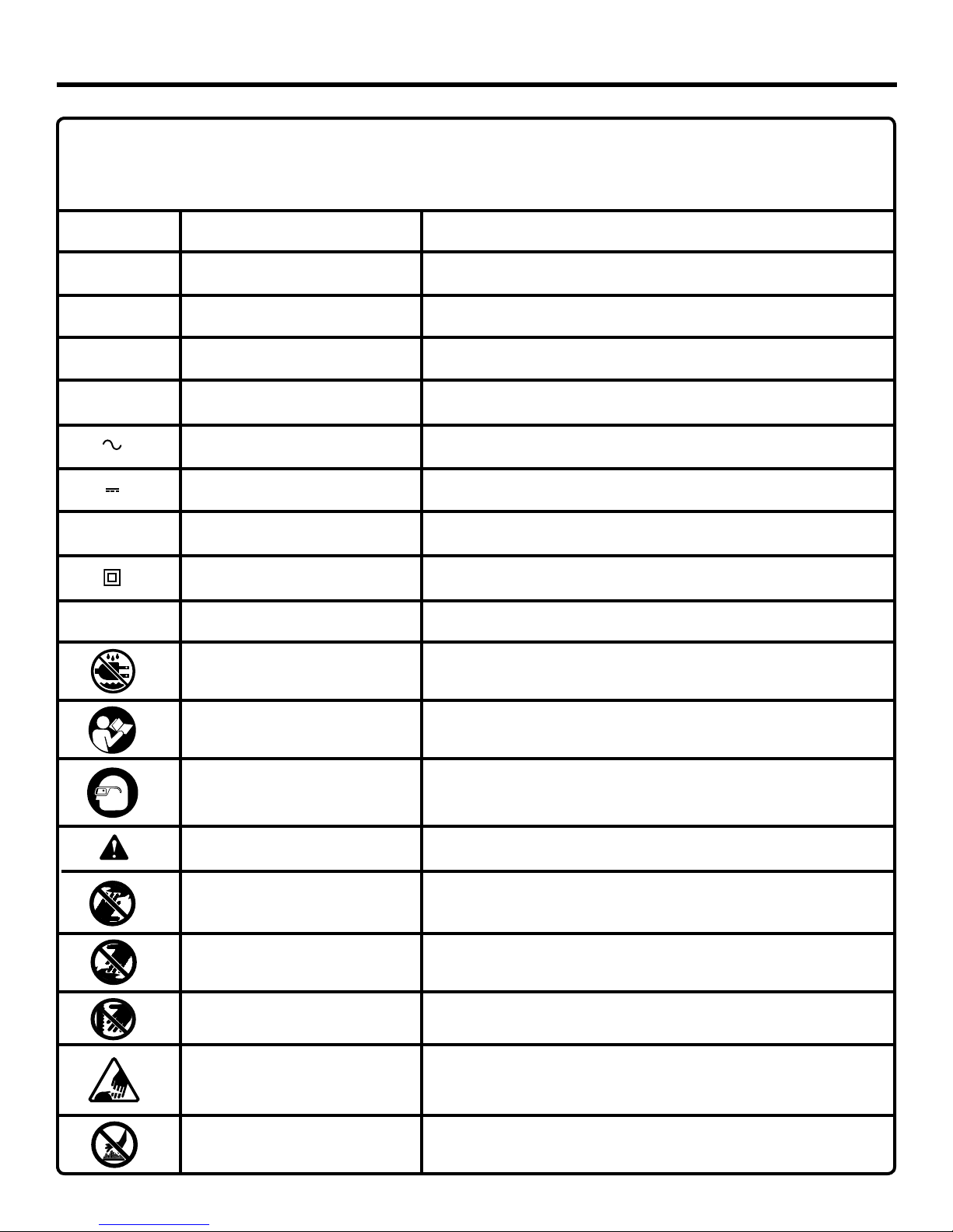
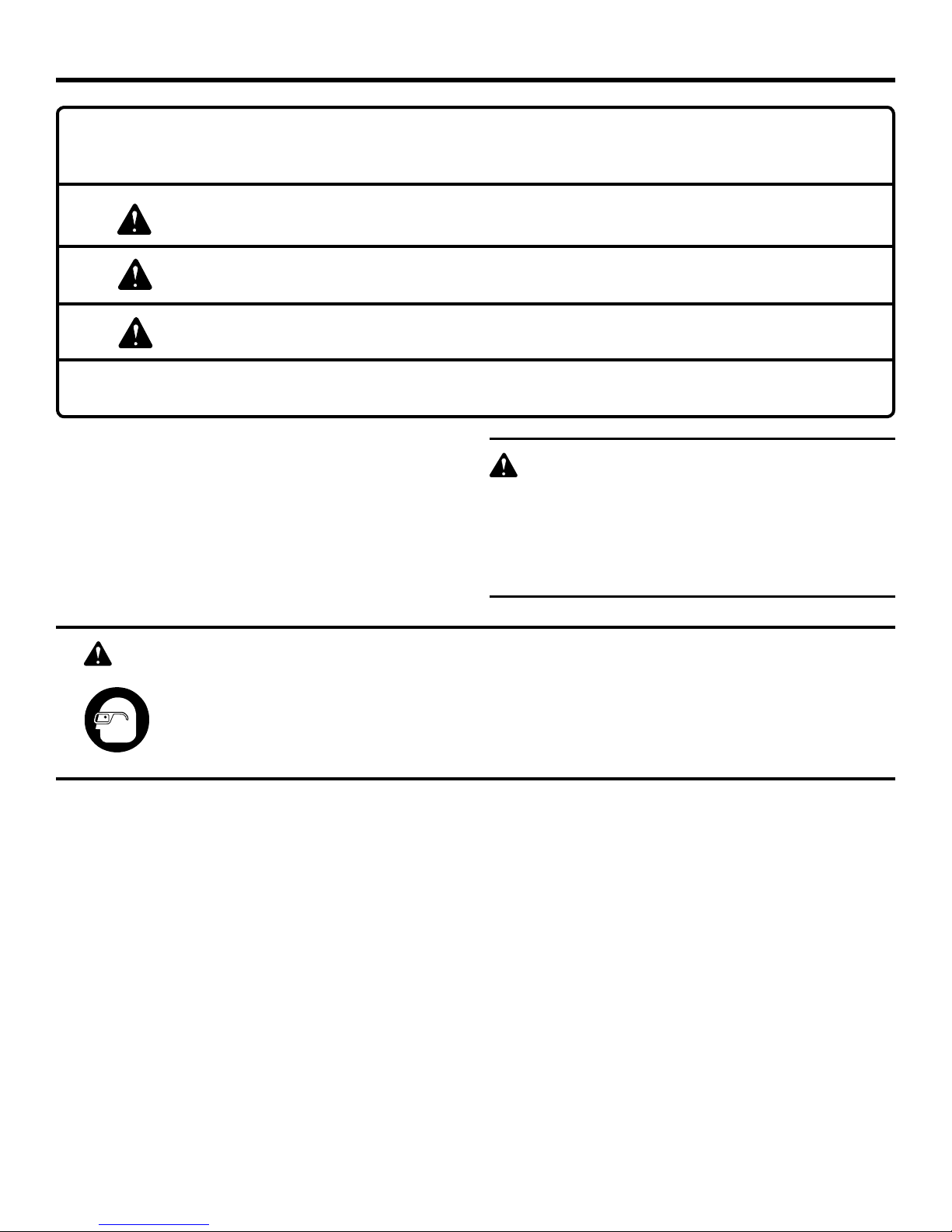
RIDGID JP06101 User manual

Your Jointer/Planer has been engineered and manufactured to RIDGID’s high standard for dependability, ease of operation,
and operator safety. When properly cared for, it will give you years of rugged, trouble-free performance.
WARNING:
To reduce the risk of injury, the user must read and understand the operator's manual before using this product.
Thank you for buying a RIDGID product.
OPERATOR'S MANUAL
6-1/8 in. JOINTER/PLANER
JP06101
SAVE THIS MANUAL FOR FUTURE REFERENCE
�

2
TABLE OF CONTENTS
nIntroduction........................................................................................................................................................................2
nGeneral Safety Rules ..................................................................................................................................................... 3-4
nSpecific Safety Rules.........................................................................................................................................................5
nSymbols......................................................................................................................................................................... 6-7
nElectrical ........................................................................................................................................................................ 8-9
nGlossary of Terms............................................................................................................................................................10
nFeatures..................................................................................................................................................................... 11-12
nTools Needed...................................................................................................................................................................12
nLoose Parts................................................................................................................................................................ 13-14
nAssembly ................................................................................................................................................................... 14-20
nOperation................................................................................................................................................................... 21-28
nAdjustments............................................................................................................................................................... 29-31
nMaintenance .............................................................................................................................................................. 32-33
nAccessories .....................................................................................................................................................................34
nTroubleshooting ......................................................................................................................................................... 34-35
nWarranty ..........................................................................................................................................................................39
nCustomer Service Information.........................................................................................................................................40
INTRODUCTION
This tool has many features for making its use more pleasant and enjoyable. Safety, performance, and dependability have
been given top priority in the design of this product making it easy to maintain and operate.

3
WARNING:
Read and understand all instructions. Failure to
follow all instructions listed below, may result in
electric shock, fire and/or serious personal injury.
READ ALL INSTRUCTIONS
n KNOW YOUR POWER TOOL. Read the operator's
manual carefully. Learn the applications and limitations
as well as specific potential hazards related to this tool.
n GUARD AGAINST ELECTRICAL SHOCK BY
PREVENTING BODY CONTACT WITH GROUNDED
SURFACES. For example: pipes, radiators, ranges,
refrigerator enclosures.
n KEEP GUARDS IN PLACE and in working order.
n REMOVE ADJUSTING KEYS AND WRENCHES. Form
habit of checking to see keys and adjusting wrenches are
removed from tool before turning it on.
n KEEP THE WORK AREA CLEAN. Cluttered work areas
and work benches invite accidents. DO NOT leave tools
or pieces of wood on the tool while it is in operation.
n DO NOT USE IN DANGEROUS ENVIRONMENTS. Do
not use power tools in damp or wet locations or expose
them to rain. Keep the work area well lit.
n KEEP CHILDREN AND VISITORS AWAY. All visitors
should wear safety glasses and be kept a safe distance
from work area. Do not let visitors contact tool or exten-
sion cord while operating.
n MAKE WORKSHOP CHILDPROOF with padlocks,
master switches, or by removing starter keys.
n DON’T FORCE THE TOOL. It will do the job better and
safer at the rate for which it was designed.
n USE THE RIGHT TOOL. Do not force the tool or attach-
ment to do a job for which it was not designed.
n USE THE PROPER EXTENSION CORD. Make sure your
extension cord is in good condition. Use only a cord heavy
enough to carry the current your product will draw. An
undersized cord will cause a drop in line voltage result-
ing in loss of power and overheating. A wire gauge size
(A.W.G.) of at least 14 is recommended for an extension
cord 25 feet or less in length. If in doubt, use the next
heavier gauge. The smaller the gauge number, the heavier
the cord.
n DRESS PROPERLY. Do not wear loose clothing, neck-
ties, or jewelry that can get caught and draw you into
moving parts. Rubber gloves and nonslip footwear are
recommended when working outdoors. Also wear protec-
tive hair covering to contain long hair.
n ALWAYS WEAR SAFETY GLASSES WITH SIDE
SHIELDS. Everyday eyeglasses have only impact-resis-
tant lenses, they are NOT safety glasses.
n SECURE WORK. Use clamps or a vise to hold work when
practical, it is safer than using your hand and frees both
hands to operate the tool.
GENERAL SAFETY RULES
n DO NOT OVERREACH. Keep proper footing and balance
at all times.
n MAINTAIN TOOLS WITH CARE. Keep tools sharp and
clean for best and safest performance. Follow instructions
for lubricating and changing accessories.
n DISCONNECT TOOLS. When not in use, before servic-
ing, or when changing attachments, blades, bits, cutters,
etc., all tools should be disconnected from power source.
n AVOID ACCIDENTAL STARTING. Be sure switch is off
when plugging in any tool.
n USE RECOMMENDED ACCESSORIES. Consult the
operator’s manual for recommended accessories. The
use of improper accessories may result in injury.
n NEVER STAND ON TOOL. Serious injury could occur if
the tool is tipped.
n CHECK DAMAGED PARTS. Before further use of the
tool, a guard or other part that is damaged should be
carefully checked to determine that it will operate properly
and perform its intended function. Check for alignment
of moving parts, binding of moving parts, breakage of
parts, mounting and any other conditions that may affect
its operation. A guard or other part that is damaged must
be properly repaired or replaced by an authorized service
center to avoid risk of personal injury.
n USE THE RIGHT DIRECTION OF FEED. Feed work into
a blade, cutter, or sanding spindle against the direction
or rotation of the blade, cutter, or sanding spindle only.
n NEVER LEAVE TOOL RUNNING UNATTENDED. TURN
THE POWER OFF. Don’t leave tool until it comes to a
complete stop.
n PROTECT YOUR LUNGS. Wear a face or dust mask if
the cutting operation is dusty.
n PROTECT YOUR HEARING. Wear hearing protection
during extended periods of operation.
n DO NOT ABUSE CORD. Never carry tool by the cord or
yank it to disconnect from receptacle. Keep cord from
heat, oil, and sharp edges.
n USE OUTDOOR EXTENSION CORDS. When tool
is used outdoors, use only extension cords with
approved ground connection that are intended for use
outdoors and so marked.
n KEEP BLADES CLEAN, SHARP, AND WITH
SUFFICIENT SET. Sharp blades minimize stalling
and kickback.
n NEVER USE IN AN EXPLOSIVE ATMOSPHERE.
Normal sparking of the motor could ignite fumes.
n INSPECT TOOL CORDS PERIODICALLY. If dam-
aged, have repaired by a qualified service technician at
an authorized service facility. The conductor with insula-
tion having an outer surface that is green with or without
yellow stripes is the equipment-grounding conductor. If
repair or replacement of the electric cord or plug is neces-
sary, do not connect the equipment-grounding conductor
to a live terminal. Repair or replace a damaged or worn
cord immediately. Stay constantly aware of cord location
and keep it well away from the rotating blade.

4
GENERAL SAFETY RULES
n INSPECT EXTENSION CORDS PERIODICALLY and
replace if damaged.
n KEEP TOOL DRY, CLEAN, AND FREE FROM OIL AND
GREASE. Always use a clean cloth when cleaning. Never
use brake fluids, gasoline, petroleum-based products, or
any solvents to clean tool.
n STAY ALERT AND EXERCISE CONTROL. Watch what
you are doing and use common sense. Do not operate
tool when you are tired. Do not rush.
n DO NOT USE TOOL IF SWITCH DOES NOT TURN IT
ON AND OFF. Have defective switches replaced by an
authorized service center.
n INSPECT FOR AND REMOVE ALL NAILS FROM LUM-
BER BEFORE USING THIS TOOL. Following this rule
will reduce the risk of serious personal injury.
n NEVER START A TOOL WHEN ANY ROTATING COM-
PONENT IS IN CONTACT WITH THE WORKPIECE.
n DO NOT OPERATE A TOOL WHILE UNDER THE
INFLUENCE OF DRUGS, ALCOHOL, OR ANY
MEDICATION.
n WHEN SERVICING use only identical replacement parts.
Use of any other parts may create a hazard or cause
product damage.
n USE ONLY RECOMMENDED ACCESSORIES listed
in this manual or addendums. Use of accessories that
are not listed may cause the risk of personal injury.
Instructions for safe use of accessories are included
with the accessory.
n DOUBLE CHECK ALL SETUPS. Make sure the spindle
or sanding belt assembly is tight and not making con-
tact with sander or workpiece before connecting to
power supply.

5
WARNING:
Some dust created by power sanding, sawing, grinding, drilling, and other construction activities contains chemicals
known to cause cancer, birth defects or other reproductive harm. Some examples of these chemicals are:
• lead from lead-based paints,
• crystalline silica from bricks and cement and other masonry products, and
• arsenic and chromium from chemically-treated lumber.
Your risk from these exposures varies, depending on how often you do this type of work. To reduce your exposure
to these chemicals: work in a well ventilated area, and work with approved safety equipment, such as those dust
masks that are specially designed to filter out microscopic particles.
n PROTECT YOUR LUNGS. Wear a face or dust mask if
the cutting operation is dusty.
n PROTECT YOUR HEARING. Wear hearing protection
during extended periods of operation.
nINSPECT TOOL CORDS PERIODICALLY AND, IF
DAMAGED, HAVE REPAIRED AT YOUR NEAREST
AUTHORIZED SERVICE CENTER. CONSTANTLY STAY
AWARE OF CORD LOCATION. Following this rule will
reduce the risk of electric shock or fire.
n INSPECT FOR AND REMOVE ALL NAILS FROM LUM-
BER BEFORE USING THIS TOOL. Following this rule
will reduce the risk of serious personal injury.
nSAVE THESE INSTRUCTIONS. Refer to them frequently
and use them to instruct others who may use this tool. If
you loan someone this tool, loan them these instructions
also.
n SMALL OR THIN WORKPIECES CAN KICKBACK
WHEN THEY TIP OVER ON THE TABLES OR INTO
THE CUTTER HEAD. To reduce the risk of cutter head
contact or workpiece kickback: Never joint, plane or bevel
workpieces shorter than 12 in.
n WHEN JOINTING never joint workpieces less than
3/4 in. wide or 1/4 in. thick.
n ALWAYS USE PUSH BLOCKS/PUSH STICK when joint-
ing or beveling wood narrower than 3 in.
n WHEN RABBETING always make cuts in 1/8 in. incre-
ments or less.
SPECIFIC SAFETY RULES
n NEVER PLANE WOOD NARROWER OR THINNER
THAN 3/4 IN.
n ALWAYS USE PUSH BLOCKS/PUSH STICK when plan-
ing.
n NEVER perform any operation "freehand" which
means using only your hands to support or guide the
workpiece. Always use either the rip fence or miter
fence to position and guide the work.
n MAKE SURE THERE’S NO DEBRIS between the
workpiece and either the fence or table top.
n ALWAYS USE A STABLE WORK SUPPORT WHEN
JOINTING OR PLANING LONG WORKPIECES. Never
use another person as additional support or to help feed,
support or pull the workpiece in any operation.
n NEVER CUT more than one workpiece at a time.
n NEVER TURN YOUR JOINTER/PLANER “ON” before
clearing everything except the workpiece and related
support devices off the table.
n AVOID AWKWARD OPERATIONS AND HAND
POSITIONS where a sudden slip could cause your
hand to move into the cutter head. Never pass either
hand over the cutter head during any operation.
n SAVE THESE INSTRUCTIONS. Refer to them frequent-
ly and use to instruct other users. If you loan someone
this tool, loan them these instructions also.

6
SYMBOLS
Some of the following symbols may be used on this tool. Please study them and learn their meaning. Proper interpreta-
tion of these symbols will allow you to operate the tool better and safer.
Read The Operator’s Manual
Safety Alert
No Hands Symbol
No Hands Symbol
No Hands Symbol
No Hands Symbol
SYMBOL NAME DESIGNATION/EXPLANATION
Voltage
Current
Frequency (cycles per second)
Power
Time
Type of current
Type or a characteristic of current
Rotational speed, at no load
Double-insulated construction
Revolutions, strokes, surface speed, orbits etc., per minute
Do not expose to rain or use in damp locations.
To reduce the risk of injury, user must read and understand
operator’s manual before using this product.
Eye Protection Always wear safety goggles or safety glasses with side shields
and a full face shield when operating this product.
Precautions that involve your safety.
Failure to keep your hands away from the blade will result in
serious personal injury.
Failure to keep your hands away from the blade will result in
serious personal injury.
Failure to keep your hands away from the blade will result in
serious personal injury.
Failure to keep your hands away from the blade will result in
serious personal injury.
Wet Conditions Alert
.../min Per Minute
Class II Construction
n
o
No Load Speed
Direct Current
Alternating Current
min Minutes
W Watt
Hz Hertz
A Amperes
V Volts
Hot Surface To reduce the risk of injury or damage, avoid contact with
any hot surface.

7
SERVICE
Servicing requires extreme care and knowledge and should
be performed only by a qualified service technician. For
service we suggest you return the product to your nearest
AUTHORIZED SERVICE CENTER for repair. When servic-
ing, use only identical replacement parts.
WARNING:
To avoid serious personal injury, do not attempt
to use this product until you read thoroughly and
understand completely the operator’s manual. Save
this operator’s manual and review frequently for
continuing safe operation and instructing others
who may use this product.
The operation of any power tool can result in foreign objects being thrown into your eyes, which can
result in severe eye damage. Before beginning power tool operation, always wear safety goggles or
safety glasses with side shields and a full face shield when needed. We recommend Wide Vision Safety
Mask for use over eyeglasses or standard safety glasses with side shields. Always use eye protection
which is marked to comply with ANSI Z87.1.
WARNING:
SAVE THESE INSTRUCTIONS
The following signal words and meanings are intended to explain the levels of risk associated with this product.
SYMBOL SIGNAL MEANING
DANGER: Indicates an imminently hazardous situation, which, if not avoided, will
result in death or serious injury.
WARNING: Indicates a potentially hazardous situation, which, if not avoided, could
result in death or serious injury.
CAUTION: Indicates a potentially hazardous situation, which, if not avoided, may
result in minor or moderate injury.
CAUTION: (Without Safety Alert Symbol) Indicates a situation that may result in
property damage.
SYMBOLS

8
Fig. 1
GROUNDING
PIN 120 V GROUNDED
OUTLET
ELECTRICAL
SPEED AND WIRING
The no-load speed of this tool is approximately
3,450/min. This speed is not constant and decreases under
a load or with lower voltage. For voltage, the wiring in a
shop is as important as the motor’s horsepower rating. A
line intended only for lights cannot properly carry a power
tool motor. Wire that is heavy enough for a short distance
will be too light for a greater distance. A line that can
support one power tool may not be able to support two
or three tools.
GROUNDING INSTRUCTIONS
In the event of a malfunc
tion or breakdown, grou
nding provides
a path of least resistance for electric current to reduce the risk
of electric shock. This tool is equipped with an electric cord
having an equipment-groundIng conductor and a grounding
plug. The plug must be plugged into a matching outlet that is
properly installed and grounded in accordance with all local
codes and ordinances.
Do not modify the plug provided. If it will not fit the outlet,
have the proper outlet installed by a qualified electrician.
Improper connection of the equipment-grounding con-
ductor can result in a risk of electric shock. The conduc-
tor with insulation having an outer surface that is green
with or without yellow stripes is the equipment-grounding
conductor. If repair or replacement of the electric cord
or plug is necessary, do not connect the equipment-
grounding conductor to a live terminal.
Check with a qualified electrician or service personnel if the
grounding instructions are not completely understood, or if
in doubt as to whether the tool is properly grounded.
Repair or replace a damaged or worn cord immediately.
This tool is intended for use on a circuit that has an outlet
like the one shown in figure 1. It also has a grounding pin
like the one shown.
EXTENSION CORDS
Use only 3-wire extension cords that have 3-prong ground-
ing plugs and 3-pole receptacles that accept the tool's plug.
When using a power tool at a considerable distance from the
power source, use an extension cord heavy enough to carry
the current that the tool will draw. An undersized extension
cord will cause a drop in line voltage, resulting in a loss of
power and causing the motor to overheat. Use the chart
provided below to determine the minimum wire size required
in an extension cord. Only round jacketed cords listed by
Underwriter's Laboratories (UL) should be used.
**Ampere rating (on tool faceplate)
0-2.0 2.1-3.4 3.5-5.0 5.1-7.0 7.1-12.0 12.1-16.0
Cord Length Wire Size (A.W.G.)
25' 16 16 16 16 14 14
50' 16 16 16 14 14 12
100' 16 16 14 12 10 —
**Used on 12 gauge - 20 amp circuit.
NOTE: AWG = American Wire Gauge
When working with the tool outdoors, use an extension cord
that is designed for outside use. This is indicated by the
letters “WA” on the cord's jacket.
Before using an extension cord, inspect it for loose or
exposed wires and cut or worn insulation.
WARNING:
Keep the extension cord clear of the working area.
Position the cord so that it will not get caught on
lumber, tools or other obstructions while you are
working with a power tool. Failure to do so can
result in serious personal injury.
WARNING:
Check extension cords before each use. If dam-
aged replace immediately. Never use tool with a
damaged cord since touching the damaged area
could cause electrical shock resulting in serious
injury.
ELECTRICAL CONNECTION
This tool is powered by a precision built electric motor. It
should be connected to a power supply that is 120 volts,
60 Hz, AC only (normal household current). Do not operate
this tool on direct current (DC). A substantial voltage drop
will cause a loss of power and the motor will overheat. If the
saw does not operate when plugged into an outlet, double
check the power supply.

9
ELECTRICAL
FOR USE WITH 110-120 VOLT
CHANGING MOTOR VOLTAGE
See Figures 2 - 5.
WARNING:
Electric shock can kill. To reduce the risk of serious
personal injury, never connect plug to power source
until all assembly steps are completed.
NOTE: The jointer/planer is prewired at the factory for 120
volts, 60 Hz. Use the following procedures to change motor
voltage from 120 volts to 240 volts.
n Unplug the jointer/planer.
n Located on the side of the motor is the junction box.
Remove the phillips screw at the back of the junction box
then lift off the cover.
n Remove and discard the electrical tape from the wire
connectors. Remove wire connectors.
n Reconnect the leads.
n Reinstall the wire connectors and wrap each wire with
two layers of new UL listed electrical tape.
n Recheck your wiring with the wiring diagrams.
n Reinstall the junction box cover using the phillips
screw.
n Cut off the 120 volt power cord plug and replace it with
a 3-prong 240 volt, 15 amp. UL listed plug.
n Connect the power cord white and black leads,
respectively, to the "hot" plug blade terminals. Connect
the power cord green grounding wire to the plug ground
prong terminal.
n Plug your jointer/planer into a 220-240 volt, 15 amp.,
3-prong receptacle.
n Make certain the receptacle is connected to a 240 volt,
AC power supply through a 240 volt branch circuit having
at least a 15 amp capacity and protected by a 15 amp
time-delay fuse or circuit breaker.
Fig. 3
240 V GROUNDED
OUTLET
Fig. 2
Fig. 4
Fig. 5
GROUNDING PIN
135248
White Black
Green
Wire
Nuts
120V
Power
Cord
120V Wiring
Motor Junction Box
148
3
5
2
Black
White Wire
Nut
240V
Power
Cord
240V Wiring
Green
Motor Junction Box
135248
White Black
Green
Wire
Nuts
120V
Power
Cord
120V Wiring
Motor Junction Box
148
3
5
2
Black
White Wire
Nut
240V
Power
Cord
240V Wiring
Green
Motor Junction Box
JUNCTION BOX
WARNING:
To prevent possible electrical hazards including
electrocution or death, have a qualified electri-
cian check the line if you are not certain that it is
properly wired.
FOR USE WITH 220-240 VOLT

10
GLOSSARY OF TERMS
Non-Through Cuts
Any cutting operation where the blade does not extend
completely through the thickness of the workpiece.
Push Blocks (for jointer planers)
Device used to feed the workpiece over the jointer planer
cutterhead during any operation. This aid helps keep the
operator's hands well away from the cutterhead.
Push Blocks and Push Sticks (for table saws)
Devices used to feed the workpiece through the saw
blade during cutting operations. A push stick (not a push
block) should be used for narrow ripping operations.
These aids help keep the operator's hands well away from
the blade.
Pilot Hole (drill presses)
A small hole drilled in a workpiece that serves as a guide
for drilling large holes accurately.
Resaw
A cutting operation to reduce the thickness of the work-
piece to make thinner pieces.
Resin
A sticky, sap-based substance that has hardened.
Revolutions Per Minute (RPM)
The number of turns completed by a spinning object in
one minute.
Ripping or Rip Cut
A cutting operation along the length of the workpiece.
Riving Knife/Spreader/Splitter (table saws)
A metal piece, slightly thinner than the blade, which helps
keep the kerf open and also helps to prevent kickback.
Saw Blade Path
The area over, under, behind, or in front of the blade. As
it applies to the workpiece, that area which will be or has
been cut by the blade.
Set
The distance that the tip of the saw blade tooth is bent (or
set) outward from the face of the blade.
Snipe (planers)
Depression made at either end of a workpiece by cutter
blades when the workpiece is not properly supported.
Throw-Back
The throwing back of a workpiece usually caused by the
workpiece being dropped into the blade or being placed
inadvertently in contact with the blade.
Through Sawing
Any cutting operation where the blade extends completely
through the thickness of the workpiece.
Workpiece or Material
The item on which the operation is being done.
Worktable
Surface where the workpiece rests while performing a
cutting, drilling, planing, or sanding operation.
Anti-Kickback Pawls (radial arm and table saws)
A devise which, when properly installed and maintained,
is designed to stop the workpiece from being kicked back
toward the front of the saw during a ripping operation.
Arbor
The shaft on which a blade or cutting tool is mounted.
Bevel Cut
A cutting operation made with the blade at any angle
other than 90° to the table surface.
Chamfer
A cut removing a wedge from a block so the end (or part
of the end) is angled rather than at 90°.
Compound Cut
A cross cut made with both a miter and a bevel angle.
Crosscut
A cutting or shaping operation made across the grain or
the width of the workpiece.
Cutter Head (planers and jointer planers)
A rotating cutterhead with adjustable blades or knives.
The blades or knives remove material from the workpiece.
Dado Cut
A non-through cut which produces a square-sided notch
or trough in the workpiece (requires a special blade).
Featherboard
A device used to help control the workpiece by guiding it
securely against the table or fence during any ripping
operation.
FPM or SPM
Feet per minute (or strokes per minute), used in reference
to blade movement.
Freehand
Performing a cut without the workpiece being guided by a
fence, miter gauge, or other aids.
Gum
A sticky, sap-based residue from wood products.
Heel
Alignment of the blade to the fence.
Kerf
The material removed by the blade in a through cut or the
slot produced by the blade in a non-through or partial cut.
Kickback
A hazard that can occur when the blade binds or stalls,
throwing the workpiece back toward operator.
Leading End
The end of the workpiece pushed into the tool first.
Miter Cut
A cutting operation made with the workpiece at any angle
to the blade other than 90°.

11
PRODUCT SPECIFICATIONS
Motor ......................................................... 1 HP Induction
Phase ....................................................................... Single
Rotation of Shaft ...................................Counterclockwise
No Load Speed .................................................3450/min.
Cuts Per Minute ............................................10,350/CPM
FEATURES
�
OUTFEED TABLE
DUST CHUTE WITH
TOOL STORAGE
ON OFF
SWITCH
STOP PIN
DEPTH
INDICATOR
CUTTER GUARD
INFEED
TABLE
FENCE TILT HANDLE
FENCE
FENCE LOCK KNOB
ANGLE GAUGE
OUTFEED TABLE
HANDWHEEL
FENCE STOPS
FENCE LOCK
KNOB
PULLEY GUARD
TABLE LOCK
SCREW
DEPTH OF CUT
HANDWHEEL
PUSH
BLOCKS
Fig. 6
BEVEL LOCK
HANDLE
Cutter Head ......................................................... 3 Knives
Input ............................ 120 V, 60 Hz, AC only, 12.0 Amps
Input .............................. 240 V, 60 Hz, AC only, 6.0 Amps
Net Weight ............................................................ 208 lbs.

12
KNOW YOUR JOINTER/PLANER
See Figure 6.
Before attempting to use this product, familiarize yourself
with all operating Features and Safety Rules.
DUST CHUTE WITH TOOL STORAGE
Allows 4 in. diameter dust collection hose. Easily slides up
and out of the way when a vacuum is not connected. Also
tool storage for knife adjustment wrenches.
OUTFEED TABLE
The section of a jointer bed which supports the workpiece
after it passes over the cutter.
FENCE LOCK KNOB
Allows fence to move across table front to back. This is done
to achieve full width of cut or to use a different (sharper) part
of cutter knives.
PULLEY GUARD
Protects user from incidental access to the motor belt and
pulley.
TABLE LOCK SCREW
Use these screws to lock infeed or outfeed table at a desired
height.
DEPTH OF CUT HANDWHEEL
By turning the handwheel you can control how much wood
will be removed from the workpiece on each cut.
90° AND 135° FENCE STOPS
When adjusted properly, these stops provide a method for
quickly moving the fence to a 90° or 135° position from the
table.
FEATURES
TOOLS NEEDED
COMBINATION
SQUARE
STRAIGHT EDGE
OPEN END WRENCH (1/2 IN.)
ADJUSTABLE WRENCH
PHILLIPS SCREWDRIVER
FENCE TILT HANDLE
Assists in positioning the fence to various bevel angles.
FENCE
Guides workpiece over cutter head.
BEVEL LOCK HANDLE
Secures the fence at the desired bevel setting.
INFEED TABLE
The section of the jointer bed upon which the workpiece
is placed before being pushed into the cutter. Its height is
adjustable which allows the operator to select the depth
of cut.
CUTTER GUARD
Helps protect the operator from the sharp knives on the cutter
head. It is spring loaded so it automatically keeps the cutter
head covered before, during, and after a cutting operation.
It must always be used.
STOP PIN
For rabbeting operations up to 1/2 in. deep, stop pin can be
pulled out to lower infeed table in 1/8 in. increments.
ANGLE GAUGE
Used to set the fence at the desired bevel angle.
ON/OFF SWITCH
Turns the tool on and off. When the key is inserted in
the switch lever, the power may be turned ON ( I ) and
OFF ( O ). When it is removed, the power cannot be turned
ON. This feature is intended to help prevent any unauthor-
ized use.
Fig. 7
The following tools (not included) are needed for making adjustments or installing the knives:

13
LOOSE PARTS
Fig. 8
The following items are included with your tool:
1. Motor and Switch Assembly......................................... 1
2. Jointer Bed Assembly................................................... 1
3. Motor Mount Bracket ................................................... 1
4. Fence Assembly ........................................................... 1
5. Dust Chute.................................................................... 1
6. Rear Panel .................................................................... 1
1
2
3
4
5
6
7
8
9
7. Front Panel ................................................................... 1
8. Right Side Panel ........................................................... 1
9. Left Side Panel ............................................................. 1
Operator's Manual (Not shown)
Hardware Blister Pack (Not shown)

14
LOOSE PARTS
UNPACKING
This product requires assembly.
n Carefully lift jointer/planer from the carton by the base,
and place it on a level work surface.
WARNING:
This tool is heavy. To avoid back injury, lift with your
legs, not your back, and get help when needed.
n Inspect the tool carefully to make sure no breakage or
damage occurred during shipping.
n Do not discard the packing material until you have care-
fully inspected and satisfactorily operated the tool.
n If any parts are damaged or missing, please call
1-866-539-1710 for assistance.
ASSEMBLY
WARNING:
If any parts are missing, do not operate this tool
until the missing parts are replaced. Failure to do so
could result in possible serious personal injury.
WARNING:
Do not attempt to modify this tool or create acces-
sories not recommended for use with this tool. Any
such alteration or modification is misuse and could
result in a hazardous condition leading to possible
serious personal injury.
Fig. 9
The following items are included with your tool:
1
234
5
6
7
8
1. Pulley Guard .................................................................1
2. V-Belt ............................................................................1
3. Angle Gauge .................................................................1
4. Cutter Guard.................................................................1
5. Push Blocks..................................................................2
6. Fence Tilt Handle..........................................................1
7. Fence Lock Knob .........................................................1
8. Handwheel....................................................................1

15
WARNING:
Do not connect to power supply until assembly is
complete. Failure to comply could result in acciden-
tal starting and possible serious personal injury.
ASSEMBLING SIDE PANELS AND MOTOR
MOUNT
See Figures 10 - 11.
n Locate the following:
Carriage Head Bolts (6), 5/16-18 x 1/2 in.
Serrated Flange Hex Nut (6), 5/16 in.
Left Panel Side (1)
Right Panel Side (1)
Motor Mount (1)
n Mount the motor mount onto the left side panel as shown.
Make sure the lower tab of the motor mount with two
holes is on the inside of the left side panel. Bolt the motor
mount to the panel using the 5/16 in. carriage head bolts
and 5/16 in. serrated flange nuts. Tighten the nuts with a
wrench.
NOTE: Make sure that the tabs of the motor mount panel
are on top of the left side panel tabs.
n Mount the right side panel to the motor mount as shown
using 5/16 in. carriage head bolts and 5/16 in. serrated
flange nuts. Tighten the nuts with a wrench.
ASSEMBLING FRONT PANEL
See Figure 12.
n Locate the following:
Carriage Head Bolts (6), 5/16-18 x 1/2 in.
Serrated Flange Hex Nuts (6), 5/16 in.
Front panel with RIDGID logo (1)
NOTE: Tabs on front panel must be on the inside of side
panel prior to securing with nuts and bolts.
n Bolt the front panel in place as shown using 5/16 in. car-
riage head bolts and 5/16 in. serrated flange nuts. Make
sure the front panel is mounted on the same side of the
base as the switch opening. The panel should bolt in
place on the backside of the left and right side panels as
shown. Tighten the nuts with a wrench.
n Tighten all bolts on the base at this time.
NOTE: It may be easier to tighten the bolt holding the
front panel on if the base is turned upside down. The rear
panel will be mounted later.
NOTE: Holes marked “A” on both front and rear panels
are not used for assembly.
ASSEMBLY
Fig. 10
Fig. 12
Fig. 11
MOTOR
MOUNT
LEFT SIDE
PANEL
FLANGE
HEX NUT
RIGHT SIDE
PANEL
FLANGE
HEX NUT
FRONT
PANEL
CARRIAGE
BOLT
CARRIAGE
BOLT
CARRIAGE
BOLT SWITCH
OPENING
“A”

16
ASSEMBLY
Fig. 14
Fig. 13
ASSEMBLING
THE LEVELING FEET
See Figure 13.
n Turn the base upside down.
n Locate the following:
Rubber Leveling Feet (4)
Flat Washer (8), 3/8 in.
Hex Nut (8), 3/8 in.
n Thread a 3/8 in. nut onto each of the leveling feet until
the nut is 1/2 in. from the foot. Do this for all four feet.
n Attach the leveling feet as shown. Place a 3/8 in. washer
on the bottom side of the foot mount tab and a washer
on top. Bolt the feet in place with the other 3/8 in. nut.
Tighten the nuts down with a wrench.
NOTE: Once the jointer is in its permanent location the
leveling feet may need to be adjusted.
ADJUSTING THE LEVELING FEET
Move the jointer/planer to the location where it will reside
during use.
To level the cabinet, loosen the nut and adjust leveling feet
up or down as needed. Adjust all four leveling feet if neces-
sary and then retighten the nut.
NOTE: These levelers are not intended for height adjustment,
only leveling adjustment.
MOUNTING THE MOTOR
See Figure 14.
n Turn the cabinet upside down and place one 4 x 4 block
under the right side of the cabinet so the base is tilted
as shown. This will elevate the motor mount so it is level
with the floor making assembly easier.
n Locate the following:
Carriage Head Bolts (4), 5/16-18 x 1/2 in.
Serrated Flange Hex Nuts (4), 5/16 in.
Motor and Switch Assembly (1)
NOTE: This motor is heavy; additional help may be needed
to secure nuts and bolts in place.
n Place the motor on the motor mount as shown. Make
sure the motor shaft faces the rear of the cabinet (away
from the side with RIDGID label).
n Bolt the motor to the motor mount using the 5/16 in. car-
riage head bolts and 5/16 in. serrated flange hex nuts.
The bolts should be placed through the motor mount into
the motor bracket as shown. Do not tighten the nuts at
this time.
NOTE: Do not assemble the switch at this time or thread
cord through cabinet.
LEVELING
FOOT
CABINET
HEX NUT
WASHER
MOTOR AND
SWITCH ASSEMBLY
4 X 4
BLOCK
MOTOR
MOUNT
CARRIAGE BOLT
FLANGE
HEX NUT

17
ASSEMBLY
ASSEMBLING JOINTER TABLE TO CABINET
See Figures 15 - 16.
WARNING:
This tool is heavy. To avoid back injury, lift with your
legs, not your back, and get help when needed.
n With help place the bed assembly upside down on two
blocks as shown.
n Place the cabinet on top of the bed assembly as
shown.
n Locate the following:
Serrated Hex Head Bolts (3), 3/8-16 x 3/4 in.
n Line up the holes in jointer table with the holes in the
cabinet.
n Bolt the jointer table to the cabinet using hex head bolts
and tighten all the bolts. To access third bolt, reach into
dust collection port on left side.
ASSEMBLING SWITCH
See Figure 17.
n Locate the following:
Switch Key (1)
Screws (2), 3/16 in.
n Using 3/16 in. screws, mount the switch into place as
shown. Make sure the switch is right side up.
n Install switch key into switch.
Fig. 15 Fig. 17
Fig. 16
BED ASSEMBLY
JOINTER CABINETHEX HEAD
BOLT
SWITCH
SCREW
BED ASSEMBLY
4 X 4'S 4 X 4'S
4 X 4'S
4 X 4'S

18
ASSEMBLY
ASSEMBLING REAR PANEL
See Figure 18.
n Locate the following:
Carriage Head Bolts (6), 5/16-18 x 1/2 in.
Hex Nuts Serrated Flange (6), 5/16 in.
Rear Cabinet Panel (1)
NOTE: Tabs on rear panel must be on the inside of side
panels prior to securing with nuts and bolts.
n Position the rear panel in place from the bottom of the
cabinet as shown. Bolt in place using 5/16 in. carriage
head bolts and 5/16 in. flange nuts. Make sure the rear
panel’s tabs are on the inside of the cabinet. Tighten the
nuts.
n Thread the power cord through the hole in the rear of the
cabinet.
n Remove the screws and washers from the cable plate.
n Thread the power cord through the hole from the inside
of the cabinet until the cord plate reaches the cabinet.
n Reinstall the washers and screws from the outside of
the cabinet with the cord plate flush against the inside
of cabinet. Retighten screws.
NOTE: Securely tighten all cabinet nuts and bolts as well
as jointer table mounting bolts at this time.
ASSEMBLING AND TENSIONING BELT
See Figure 19.
n Locate the V-belt.
n Slip the V-belt over both the motor and cutter head
pulleys.
n While the jointer is still upside down, slide the motor up the
motor mount to put tension on the V-belt. This will require
assistance. Once the V-belt has been tensioned, tighten
the motor bolts. The V-belt should have approximately
1 in. deflection (the measurement of how much you can
push in on one side of the V-belt).
NOTE: An alternate method for tensioning the V-belt is to
turn the unit upright, letting the motor slide down in the
slots and allowing the weight of the motor only to tension
the V-belt.
n Visually check the front to back alignment of the pulleys
and adjust the motor as needed.
ASSEMBLING THE PULLEY GUARD
See Figure 20.
n Locate the following:
Cross Serrated Pan Head Screws (4), 3/16-24 x 3/8 in.
Pulley guard (1)
n With assistance, set the jointer upright.
WARNING:
This tool is heavy. To avoid back injury, lift with your
legs, not your back, and get help when needed.
n Mount the pulley guard in place as shown using 3/16 in.
screws.
Fig. 18
Fig. 20
Fig. 19
REAR PANEL
CABINET
V-BELT
SLOTS
1 IN. BELT
DEFLECTION
PAN HEAD
SCREW
PULLEY GUARD

19
ASSEMBLY
ASSEMBLING HANDWHEEL
See Figure 21.
n Locate the following:
Pan Head Screw with Washer (1), 1/4-20 x 5/8 in.
Handwheel (1)
n Slip the handwheel onto the infeed table elevation shaft
and install the pan head screw with washer as shown.
ASSEMBLING DUST CHUTE
See Figure 22.
n Locate the following:
Sawdust Chute (1)
Wing Screws (2), 1/4-20 x 1/2 in.
Wrench Box (1), 8mm/10mm
Hex Key (1), 3mm
n Slide the tab on the bottom side of the dust chute into
the slot just below the chute on the left side of the base.
Fasten the dust chute on with wing screws through the
slots on both sides of the dust chute.
n The hex key and open end wrench (supplied with the
jointer) used for knife adjustments, can be conveniently
stored in the dust chute as shown.
NOTE: If a dust collection system is not in use, simply
loosen the wing screws, lift the bottom of the chute up,
out, and then slide the dust chute up and retighten the
wing screws.
ASSEMBLING FENCE ASSEMBLY TO
BED ASSEMBLY
See Figure 23.
n Locate the following:
Washer (1),1/2 in.
T-Nut (1)
Fence Assembly (1)
Fence Lock Knob (1)
Fence Tilt Knob (1)
NOTE: While installing the fence, the two ribs on top of the
fence indicate where the cutter head opening is located
in the table.
NOTE: While installing fence to table, do not remove the
protective cutter guard covering.
n Position fence onto fence support as shown, making sure
the keyway in fence assembly lines up with the key on
the fence mount.
n Once fence is in place, slide the fence lock knob through
the 1/2 in. washer and then through the fence assembly
and fence mount. Thread T-nut onto the end of the lock
knob. Make sure the tabs on the nut sit in the slot on the
fence mount.
NOTE: Tabs on T-nut must be positioned upwards so
they fit in slot.
n Slide the fence back and fourth to make sure it moves
freely. Then lock in place.
n Thread the fence tilt knob into the fence.
Fig. 21
Fig. 22
Fig. 23
HANDWHEEL
PAN HEAD
SCREW
ELEVATION
SHAFT
DUST CHUTE
WING SCREW
FENCE
ASSEMBLY
FENCE MOUNT T-NUT
FENCE LOCK
KNOB

20
ASSEMBLY
ASSEMBLING CUTTER GUARD
See Figure 24.
n Locate the following:
Cutter Guard Assembly (1)
n Remove the pan head screw from the bottom of the cutter
head guard post.
n Turn the spring-loaded knob one turn counterclockwise,
while looking down through the hole in the infeed table.
n While looking down through the hole in the infeed table,
align the slot in the guard post with the spring in the knob.
Slide the post through infeed table and over the spring in
the knob.
NOTE: The cutter guard stop post limits the amount of
cutter guard travel. Never modify the stop post or remove
cutter guard before any operation.
n Reinstall the pan head screw in the bottom of the guard
post.
CUTTER GUARD FUNCTIONAL CHECK
With the power off, check the guard to make sure it is func-
tioning properly.
WARNING:
Cutter guard helps provide protection over the
cutter head. It must always be in place and func-
tioning properly to avoid injury from contact with
the cutter head.
n Position the fence to the rear of the bed for maximum
width of cut. Do not position fence beyond rear edge of
cutter knives.
n Pass a 1/4 in. thick piece of wood over the cutter head
between the guard and the fence.
The guard must return automatically to a “rest position”
against the fence when free of the wood. If guard does not
return quickly, adjust the guard spring, as described in the
adjustments section.
CUTTER GUARD STOP POST
The cutter guard stop post is designed to limit the outward
swing of the cutter head guard. If the stop post does not
stop the outward swing of the guard, the post is inserted
too deeply. Tap the cutter guard stop post from up under the
table with a punch or nail set. Tap the post slightly to adjust
for proper clearance and function.
Fig. 24
12
38
14
18
DEPTHOFCUT
SLOT
CUTTER
GUARD
PAN HEAD
SCREW
KNOB
COUNTER CLOCKWISE
TOP VIEW
CUTTER
GUARD
STOP POST
GUARD
SPRING
Other manuals for JP06101
2
Table of contents
Other RIDGID Planer manuals

RIDGID
RIDGID JP0610 User manual

RIDGID
RIDGID R848 User manual

RIDGID
RIDGID TP13000 User manual

RIDGID
RIDGID TP1300 User manual

RIDGID
RIDGID R888 User manual

RIDGID
RIDGID R4330 User manual

RIDGID
RIDGID TP1300 User manual

RIDGID
RIDGID TP1300 User manual

RIDGID
RIDGID JP06101 User manual

RIDGID
RIDGID R848 User manual