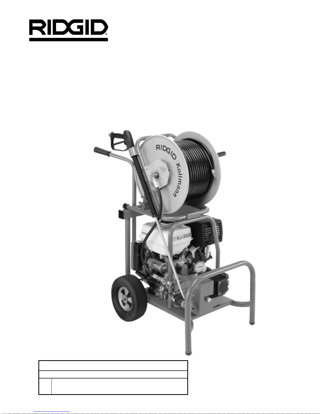
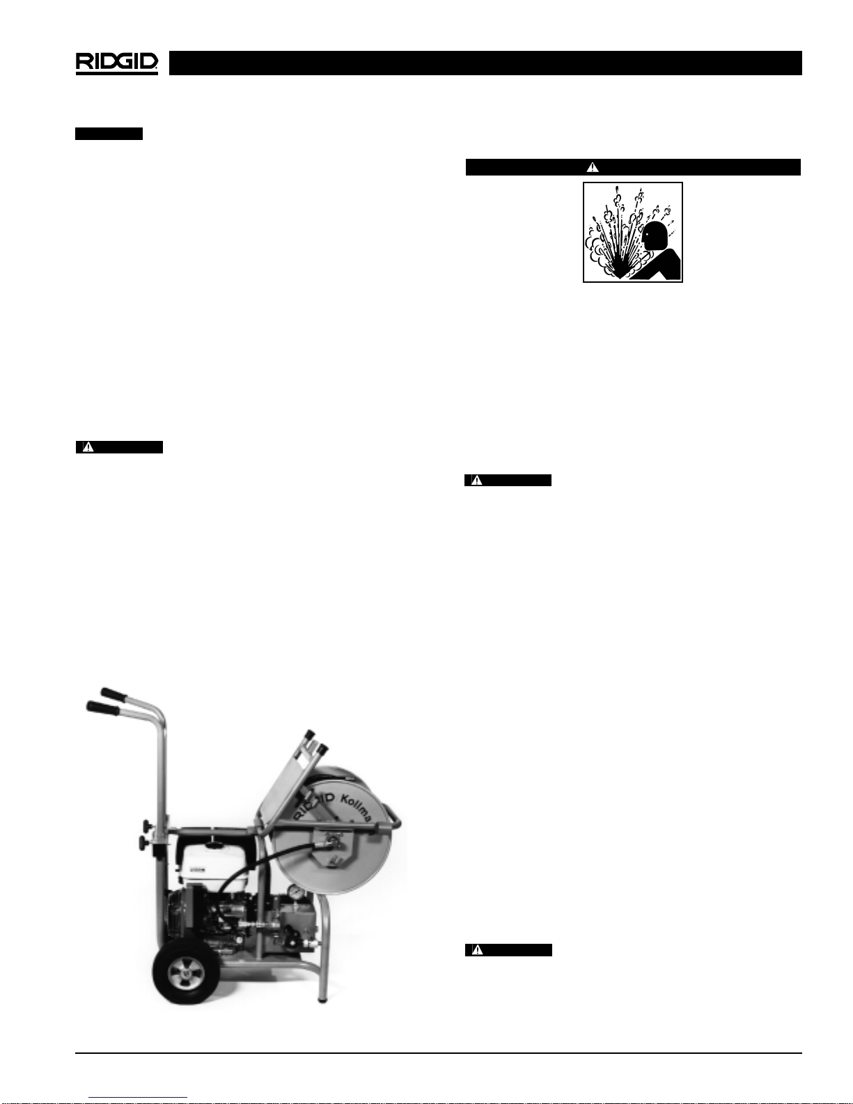
KJ-3000 Water Jetter Machine
Ridge Tool Company2
General Safety Information
WARNING! Read and understand all instructions. Failure
to follow all instructions listed below may
result in carbon monoxide poisoning, fire
and/or serious personal injury.
SAVE THESE INSTRUCTIONS!
Work Area Safety
•Keep your work area clean and well lit. Cluttered
benches and dark areas invite accidents.
•Do not operate tools in explosive atmospheres,
such as in the presence of flammable liquids, gases,
or dust. Power tools create sparks which may ignite the
dust or fumes.
•Keep bystanders, children, and visitors away while
operating a tool. Distractions can cause you to lose
control.
•Keep the engine at least one meter (3 feet) away
from buildings and other equipment during oper-
ation. Do not place flammable objects close to
engine. Procedures should be followed to prevent fire
hazards and to provide adequate ventilation.
Personal Safety
•Stay alert, watch what you are doing and use com-
mon sense when operating a power tool. Do not
use tool while tired or under the influence of drugs,
alcohol, or medications. A moment of inattention
while operating power tools may result in serious per-
sonal injury.
•Dress properly. Do not wear loose clothing or jew-
elry. Contain long hair. Keep your hair, clothing, and
gloves away from moving parts. Loose clothes, jew-
elry, or long hair can be caught in moving parts.
•Remove adjusting keys or wrenches before turning
the tool ON. A wrench or a key that is left attached to
a rotating part of the tool may result in personal injury.
•Do not over-reach. Keep proper footing and bal-
ance at all times. Proper footing and balance enables
better control of the tool in unexpected situations.
•Use safety equipment. Always wear eye protection.
Dust mask, non-skid safety shoes, hard hat, or hear-
ing protection must be used for appropriate conditions.
Tool Use and Care
•Do not force tool. Use the correct tool for your
application. The correct tool will do the job better and
safer at the rate for which it is designed.
•Store idle tools out of the reach of children and
other untrained persons. Tools are dangerous in
the hands of untrained users.
•Maintain tools with care. Keep valves, hoses and
nozzles in proper operating condition. Properly
maintained tools are less likely to malfunction and
cause injury.
•Check for misalignment or binding of moving parts,
breakage of parts, and any other conditions that
may affect the tool’s operation. If damaged, have the
tool serviced before using. Many accidents are
caused by poorly maintained tools.
•Use only accessories that are recommended by the
manufacturer for your tool. Accessories that may
be suitable for one tool may become hazardous when
used on another tool.
•Disconnect the spark plug wire before making any
adjustment or repairing tool. Such preventative mea-
sures reduce the risk of starting the tool accidentally.
•Keep handles dry and clean; free from oil and
grease. Allows for better control of the tool.
Service
•Tool service must be performed only by qualified
repair personnel. Service or maintenance performed
by unqualified repair personnel could result in injury.
•When servicing a tool, use only identical replace-
ment parts. Follow instructions in the Maintenance
Section of this manual. Use of unauthorized parts or
failure to follow maintenance instructions may create a
risk of injury.
Specific Safety Information
WARNING
Read this operator’s manual carefully before using
the RIDGID KJ-3000 Water Jetter. Failure to under-
stand and follow the contents of this manual may
result in carbon monoxide poisoning, fire and/or se-
rious personal injury.
Call the Ridge Tool Company, Technical Service Depart-
ment at (800) 519-3456 if you have any questions.
Jetter Safety
•Do not operate above 3000 psi or 140°F (inlet water
temperature). Tool will do a better and safer job if op-
erated at recommended pressures and temperatures.
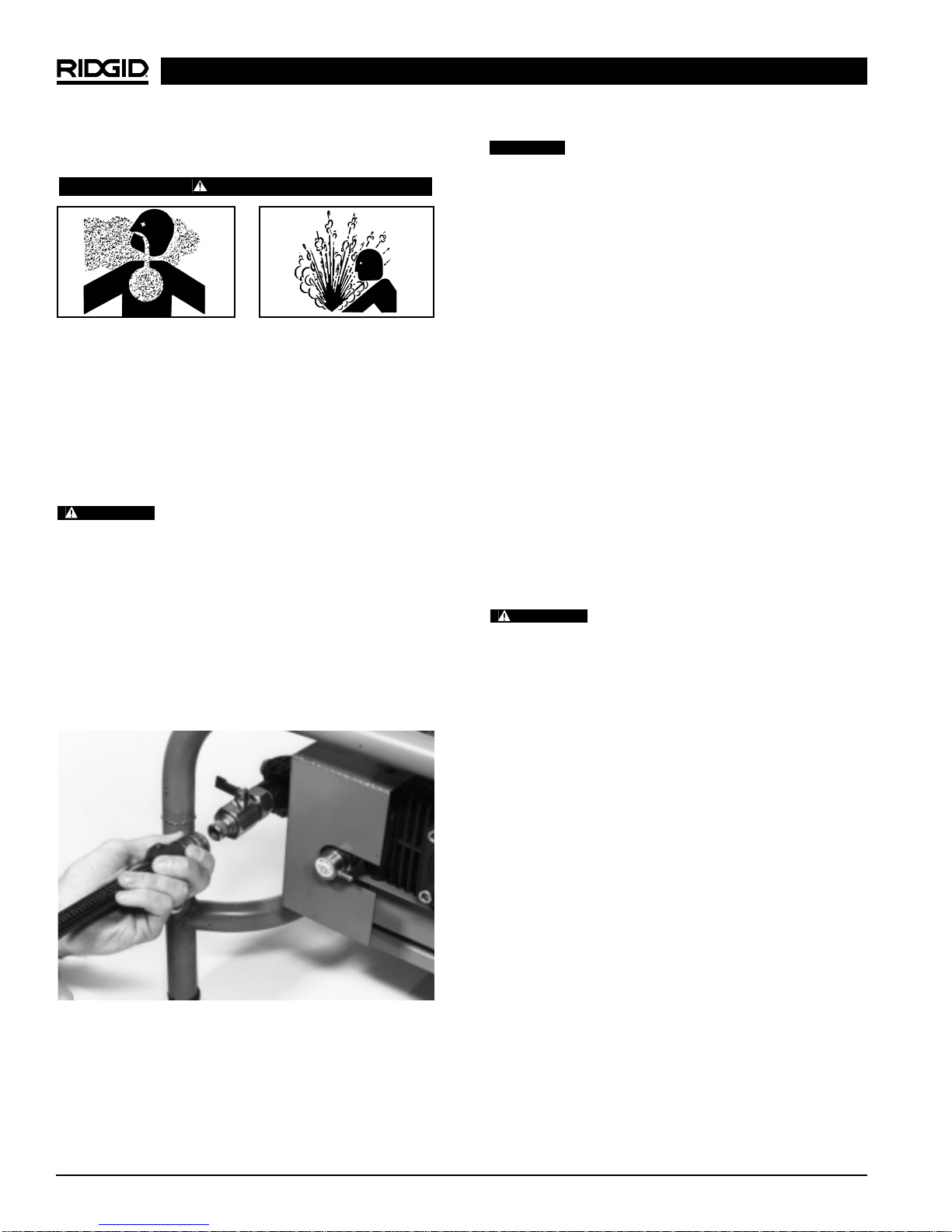
•Never permit the end of hose to rotate out of the
pipe being cleaned. Hose can whip, causing injury and
nozzle spray can penetrate skin causing serious injury.