Sealey PWM2500.V2 User manual

220BAR PRESSURE WASHER 600L/HR 6.5HP
PETROL
MODEL NO: PWM2500.V2
Thank you for purchasing a Sealey product. Manufactured to a high standard, this product will, if used according to these
instructions, and properly maintained, give you years of trouble free performance.
IMPORTANT: PLEASE READ THESE INSTRUCTIONS CAREFULLY. NOTE THE SAFE OPERATIONAL REQUIREMENTS, WARNINGS & CAUTIONS. USE
THE PRODUCT CORRECTLY AND WITH CARE FOR THE PURPOSE FOR WHICH IT IS INTENDED. FAILURE TO DO SO MAY CAUSE DAMAGE AND/OR
PERSONAL INJURY AND WILL INVALIDATE THE WARRANTY. KEEP THESE INSTRUCTIONS SAFE FOR FUTURE USE.
1. SAFETY
1.1. GENERAL SAFETY
WARNING! RISK OF FLUID INJECTION. This washer operates at fluid pressures and velocities high enough to penetrate
human and animal flesh. If there is an occurrence of fluid injection seek medical help immediately
WARNING! Stop the engine and disconnect the mains water supply before changing accessories or performing any maintenance.
WARNING! DO NOT operate the washer if damaged. Replace or repair using recommended parts only. Unauthorised parts may be
dangerous and will invalidate your warranty. Use authorised Service agent only.
WARNING! DO NOT direct jet against yourself or others in order to clean clothes or foot-wear.
9Keep the washer in good condition. Regular maintenance will give the best and safest performance.
9Ensure you comply with the water supply company regulations before connecting to the mains. If you are connecting to the mains
drinking water supply ensure you have a back flow preventer valve installed.
9The water supply hose must be reinforced and have an internal diameter of 13mm (1/2”). The minimum water supply rate must be at
least equal to the cleaner capacity. The water temperature must not exceed 50°C and the pressure must not exceed 10bar.
WARNING! DO NOT operate the washer without the water supply connected. To do so will damage the machine.
9Position the washer as near as possible to the mains water supply.
9Only use recommended washing detergents. Failure to do so may cause corrosion to equipment and hoses.
WARNING! Use the washer on a at, level surface, in a horizontal position. Failure to do so will invalidate your warranty.
9Wear safety goggles and adequate protective clothing and anti-slip rubber soled footwear.
WARNING! The high pressure jet must be used with caution. Ensure you aim the lance correctly at the work surface. Failure to do so
may scatter loose particles at the same force as the water pressure, resulting in possible damage or personal injury.
9Keep all persons and animals at a safe distance from the hose working area. It is difficult to give an exact safe distance as it will depend
upon your circumstances. We recommend at least 15 metres (16 yards). Also ensure other persons are aware before you start to
depress the washer trigger.
9Hold the gun firmly for it will tend to “kick” backwards when you first pull the trigger.
8DO NOT allow children or untrained persons to operate the washer.
8DO NOT connect other appliances to the washer inlet or outlet. Only use the supplied or recommended outlet nozzle.
8DO NOT use the washer if the water supply hose is damaged. Also check that the hose is laid out straight and safely.
8DO NOT jam the operating trigger in the operating position, and DO NOT pull the trigger without holding and aiming the gun correctly.
WARNING! DO NOT attempt to alter the pressure regulating valve as this may cause serious damage.
8DO NOT move the washer by pulling on the high pressure hose or the mains water supply hose. Use the machine handle.
8DO NOT direct jet against yourself, other persons or animals, electrical equipment or the machine itself.
WARNING! DO NOT leave the engine running for more than 2 minutes without operating the trigger, as temperature/pressure increase
may damage the sealing system.
8DO NOT use the washer if you are tired or under the influence of alcohol, drugs or intoxicating medication.
9Ensure that the hose pressure is discharged before disconnecting the mains water hose.
9 When not in use, disconnect from the water supply. Clean and dry the washer and store in a safe, dry, frost protected, childproof area.
8DO NOT allow the machine to become frozen.
1.2. ENGINE SAFETY
WARNING! Check the engine oil level before each start up. Only use an approved oil and never operate the engine with insufcient
oil.
WARNING! DO NOT touch spark plug or plug lead whilst the engine is running; severe, potentially fatal, electric shock may result.
9For safety instructions relative to the maintenance and use of the petrol engine refer to the engine instruction manual.
9Ensure that only the correct fuel type and grade is used.
8DO NOT check ignition system by removing the spark plug or spark plug lead. Use specific tester or contact service agent.
8DO NOT use combustion engine powered machines indoors unless adequate ventilation is assessed by national labour authority.
PWM2500.V2 Issue 1 29/11/19
Original Language Version
© Jack Sealey Limited
Refer to
instructions
Hot surfaces
Wear eye
protection
Wear ear
protection
WARNING: The engine is shipped without oil.
The pump is shipped with oil. Therefore only
the engine must be lled with the correct type
and quantity of oil.
See section 3 for Oil specications
Wear protective
gloves
Wear safety
footwear
Wear protective
clothing
DO NOT direct jet
against yourself,
other
persons, animals,
electrical
equipment or
the machine itself

8DO NOT use the washer with flammable, toxic or corrosive liquids. Use Sealey detergents recommended in section 4.8.7.
8DO NOT leave the washer unattended whilst operating and DO NOT remove the fuel cap whilst the engine is running.
8DO NOT refuel the engine whilst it is running. Stop the engine and allow it to cool for two minutes before attempting to refuel.
8DO NOT refuel in a closed or poorly ventilated environment as there is a danger of explosion or fire. Refuel outdoors.
8DO NOT smoke or place the washer near any naked flames whilst re-fuelling.
8DO NOT operate washer if there is a fuel leak. Move the unit and avoid using until the leak has been fixed and the machine is dry.
8DO NOT start the engine if there are any flammable materials near the exhaust system or in the path of the exhaust gases.
8DO NOT block the engine ventilation grilles.
9Ensure engine fuel is stored in an approved container.
9For long term storage ensure the fuel is drained and that the washer is adequately protected against frost.
8DO NOT operate the engine with either the silencer or air filter removed.
8DO NOT touch the engine during or after use. To avoid burns allow it to cool before handling.
WARNING! The warnings referred to in this guide cannot cover all possible conditions and situations that may occur. It must be
understood that common sense and caution are factors which cannot be built into this product, but must be applied by the operator.
NOTE: This appliance is not intended for use by persons (including children) with reduced physical, sensory or mental capabilities or lack
of experience and knowledge, unless they have been given supervision or instruction concerning the use of the appliance by a
person responsible for their safety. Children should be supervised to ensure that they DO NOT play with the appliance.
2. INTRODUCTION
Petrol powered pressure washer with recoil starting. Ideal for commercial applications with 5m pressure hose, 1m gun and lance and
adjustable nozzle. Low-pressure liquid detergent injection system with provision for detergent bottle storage. Safety latch on trigger and
automatic low-oil engine shutdown reduce risk of misuse and equipment damage. Unit stands on four legs, two with sucker feet to prevent
movement and tilts back onto two pneumatic tyres for moving. Supplied with tools.
3. SPECIFICATION
Model No:........................................................ PWM2500.V2
Engine Capacity:.......................................................... 196cc
Engine Power:............................................................... 6.5hp
Engine Type: ........................4-Stroke, Single Cylinder, Petrol
Fuel Consumption: ................................................2.1-2.6L/hr
Fuel Tank: .......................................................................... 4L
Hose Length:..................................................................... 5m
Manifold Pressure: ....................................... 175bar(2538psi)
Maximum Inlet Temperature:.......................................... 50°C
Maximum Pressure: ..................................... 220bar(3190psi)
Nozzle:.............................. 0°, 15°, 25°, 40° Fan & Detergent
Starting: ....................................................................... Recoil
Water Flow:................................................................540L/hr
Engine Oil (not included).....................................SAE10W-30
Max inlet water pressure ............................................1.0MPa
Min inlet water pressure .............................................0.2MPa
g.1
Original Language Version
© Jack Sealey Limited PWM2500.V2 Issue 1 29/11/19

4. ASSEMBLY AND PREPARATION
Unpack contents and check to ensure all parts are in good condition. If you experience any
problems contact your stockist immediately.
4.1. WHEEL ASSEMBLY FIG.2
NOTE: Make sure that there is enough air in wheel before assembly.
4.1.1. Lift the frame (fig.2.A) with one hand and attach one of the wheels (fig.2.B) by pressing the
wheel’s pin and inserting the wheel shaft into the main frame (fig.2.A). Align the pin with the
hole on the frame (fig.2.A) until it snaps in. Repeat it for the opposite side.
4.2. FRAME ASSEMBLY FIG.3
4.2.1. Place the handle assembly flat onto the main frame. Attach handle assembly to frame through
square neck bolt. Screw the knob on from outside of the frame. Handles can be folded forward
for storage (fig.3)
4.3. HOSE HOOK ASSEMBLY FIG.5
4.3.1. Attach the hose hook (fig.5.H) to the back of the panel until it slides into place.
4.4. GUN HOLSTER ASSEMBLY FIG.4
4.4.1. Attach the gun holster (fig.4.C.G) to the frame side, slide down till it clicks
into in place.
4.5. HOSE CONNECTIONS FIG.7
4.5.1. Detach the quick connector from pump water inlet and screw it to a garden
hose. Then attach them to the pump water inlet.
4.6. GUN & WAND ASSEMBLY FIG.7
4.6.1. Assemble the spray gun with the metal wand. Pull back the rubber piece
to expose the threaded fitting. Then, screw the two pieces together and
move the rubber piece back.
4.6.2. Insert the desired tip to the gun tip connector.
4.7. GUN & HOSE CONNECTIONS FIG.7
4.7.1. Take out transit plug from pump outlet. Connect one end of the high
pressure hose to pump outlet, and secure the plastic nut. Connect the
other end the pressure gun, and fasten the plastic nut.
4.7.2. Connect the mains water supply hose to the pump inlet as shown in fig.7.
USE COLD WATER ONLY.
NOTE: The water supply hose must be reinforced and have an internal diameter
of 13mm (1/2”). The minimum water supply rate must be at least equal
to the washer flow rate.
g.2
g.3
g.4
g.5
g.6
g.7
Original Language Version
© Jack Sealey Limited PWM2500.V2 Issue 1 29/11/19

4.8. USING SPRAY NOZZLE
4.8.1. This pressure washer comes with five different nozzles that can be installed on the metal wand (fig.1).
4.8.2. The spray pattern is adjusted by installing the appropriate spray nozzle.
4.8.3. 0° (red): Thin and powerful stream of water for difficult stains and debris removal
4.8.4. 15° (yellow): Thin-angled spray for detailed cleaning
4.8.5. 25° (green): Medium-angled spray for detailed cleaning
4.8.6. 40° (white): Large pattern for wider cleaning applications
4.8.7. Detergent (black): This nozzle must be used together with a cleaning detergent at a low pressure. Use only this nozzle when using a
detergent. Use Sealey Car Shampoo, SCS006 (5ltr). Traffic Film Remover is also available, SCS002 (25ltr) or SCS001 (5ltr).
4.8.8. Installing spray nozzle to the quick-connect coupler:
4.8.9. Pull the coupler ring back and insert the desired nozzle.
4.8.10. Release the coupler ring to lock it back in place.
WARNING!
a) Avoid sudden bursts of water as this will cause the water pressure to drop and put extreme pressure on the hoses and connections.
b) If another person is using water from the same supply as the washer, the water pressure will drop. Switch the engine off immediately
and wait until the pressure is restored.
4.9. ENGINE LUBRICATION
4.9.1. The pressure washer engine is shipped from the factory without
oil. DO NOT attempt to start the engine before the sump has
been filled with the correct amount of oil. Refer to the
section 5.7.
4.10. FUEL
4.10.1. Fill the petrol tank with fresh unleaded petrol. Keep fuel level
on or below the fuel level indicator in the fuel filter which sits
in the neck of the tank.
4.11. WATER SUPPLY (COLD WATER ONLY)
4.11.1. The unit must be used with cold water supply only. The water
hose must be at least ½” (13 mm) in diameter.
4.11.2. The water ow rate must not fall below 18 litres per minute
(LPM) (4 gallons per minute (GPM)), or the pump might be
damaged. The ow rate can be determined by running water
for one minute into an empty container.
4.11.3. The water supply temperature must not exceed 40°C (104°F).
4.12. ADJUSTING WATER PRESSURE
4.12.1. The water pressure can be adjusted using the throttle
(fig.9).
4.12.2. Move the switch to FAST position to increase the engine
speed, thus increasing the water pressure. Move it towards
SLOW position to decrease the engine speed, thus
decreasing the water pressure.
5. OPERATION
WARNING! THE PRESSURE WASHER ENGINE IS SHIPPED FROM THE
FACTORY WITHOUT OIL. FILL BEFORE FIRST USE.
WARNING! RISK OF FLUID INJECTION. This washer operates at fluid pressures
and velocities high enough to penetrate human and animal flesh. If there is an
occurrence of fluid injection seek medical help immediately.
WARNING! Ensure you read, understand and apply Section 1 safety instructions.
WARNING! Dry running can seriously damage the unit.
WARNING! DO NOT leave motor running for more than 2 minutes without operating
the trigger, as temperature/pressure increase may damage sealing system.
5.1. STARTING PRESSURE WASHER
5.1.1. Detach the quick connector from the pump water inlet and screw it to a garden
hose. Then attach them to pump water inlet. Attach the other end of the
garden hose to a water source.
5.1.2. Turn on the water tap. The water ow rate must not fall below 18 litres per minute
(4 gallons per minute), or the pump might be damaged.
5.1.3. Release the trigger safety lock (fig.7) if it is locked. Purge the air by squeezing
the trigger on the gun until there is a steady stream of water.
5.1.4. Install appropriate spray nozzle.
5.1.5. Start the engine. (→ Section 5.2 Starting Engine)
5.1.6. Position the tip of the wand 6-8˝(15-20 cm) away from the surface to be cleaned, at
an angle appropriate to the spray nozzle used (0°, 15°, 25° or 40°).
5.2. STARTING ENGINE
IMPORTANT Before each use:
9 Check the oil and fuel level and ll if necessary.
9 Make sure that spark plug, mufer, fuel cap, and air lter are in place and secured.
8DO NOT crank engine with spark plug removed.
5.2.1. See Section 5.1 Starting Pressure Washer to start the pressure washer.
5.2.2. Rotate the engine switch clockwise to the ON position. See g.10.
5.2.3. Fig.9 shows the fuel tap in the OFF position. Push the fuel tap over to the right to the open position.
5.2.4. If the engine is cold move the choke lever to the left to close the choke (g.9).
5.2.5. Move the throttle lever left to the fully open position then ease it back slightly.
g.8
g.9
Original Language Version
© Jack Sealey Limited PWM2500.V2 Issue 1 29/11/19

5.2.6. Take hold of the recoil starter handle (see g.9) and pull it slowly until you feel
resistance, then let it return slowly.
5.2.7. Now pull the starting handle hard and fast all the way out. Use two hands if
necessary.
5.2.8. If the engine doesn’t start repeat the process from 5.2.2.
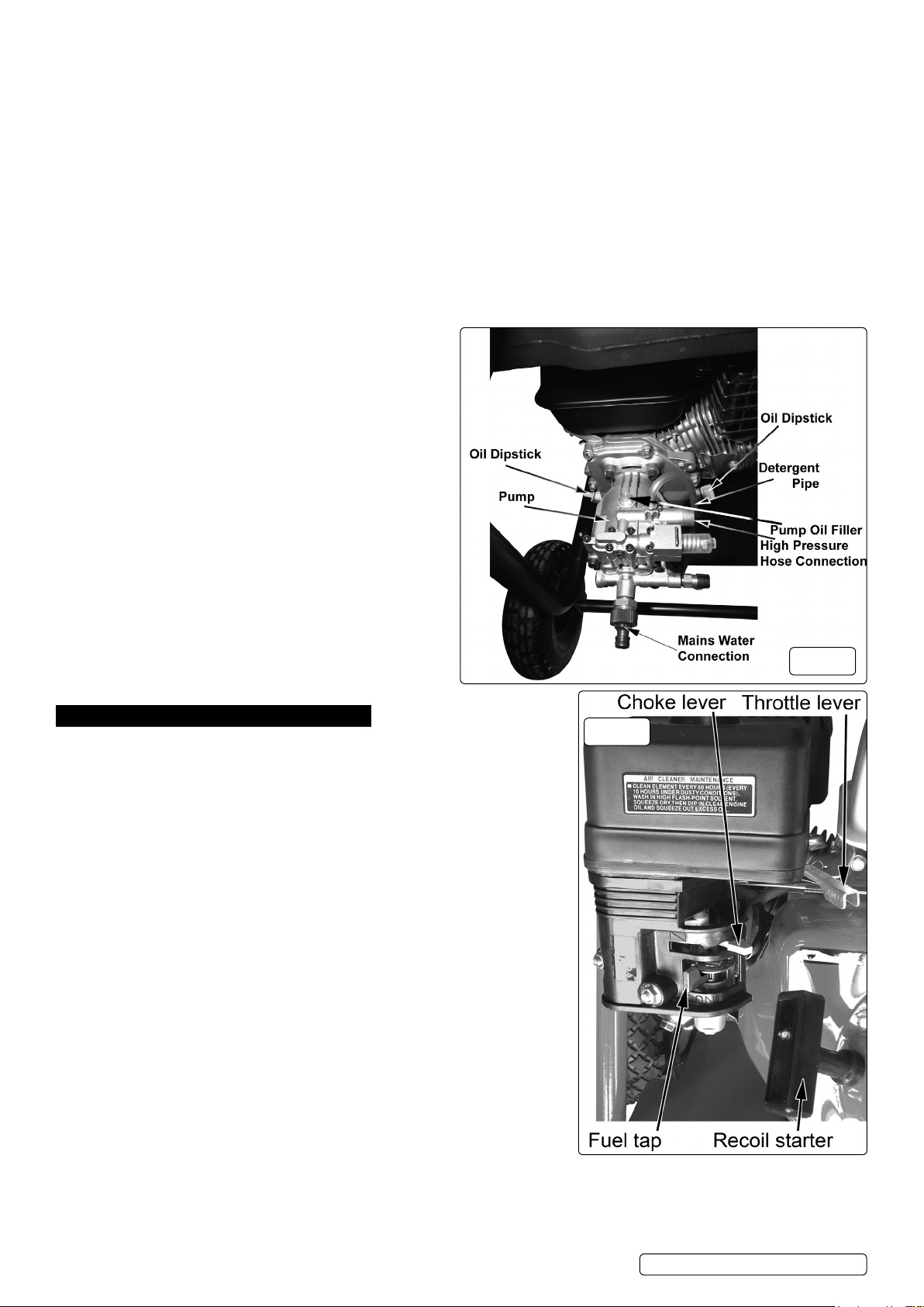
5.2.9. Once started adjust throttle lever to the required setting and return the choke to the
open position when the engine is warm.
5.3. SHUT DOWN PROCEDURE
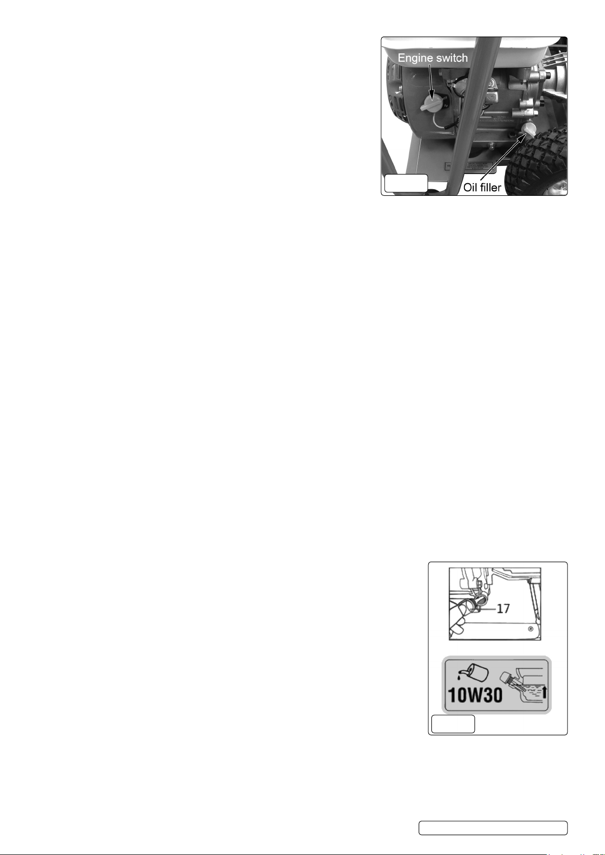
5.3.1. When you have nished cleaning, stop the engine by pushing the throttle lever fully
to the right. (See g.9) and turn the engine switch to the OFF position.
5.3.2. Turn off the fuel tap. (See g.9)
5.3.3. In an emergency turn the engine switch to the OFF position.
WARNING! DE-PRESSURIZE After cleaning is completed, turn off the water
supply and pull the trigger to de pressurize the unit. Failure to do so might result
in personal injury due to discharge of high-pressure water.
5.4. CLEANING WITH DETERGENTS
IMPORTANT This pressure washer is intended for use with special pressure washer detergents only. DO NOT use powdered soaps,
this will clog the injection system. Follow the detergent manufacturer’s directions.
IMPORTANT Working with a detergent ensures quick soaking of the dirt, and allows the high-pressure water to penetrate and remove
the dirt more effectively. Always spray detergent on a dry surface, DO NOT pre soak the area. Soaking the surface dilutes the
detergent and reduces its cleaning ability.
WARNING Damage may occur to painted surfaces if chemicals (detergents) are allowed to dry on them. Wash and rinse a small section
at a time. Avoid working on hot surfaces or under direct sunlight.
5.4.1. When using detergent, always use the black detergent nozzle.
5.4.2. When applying detergents, always operate the unit at a low water pressure throttle (fig.9) (set to SLOW position).This provides a
gentle application of the detergent, with the water pressure equivalent to a garden hose. Always test the detergent in a concealed area
before use.
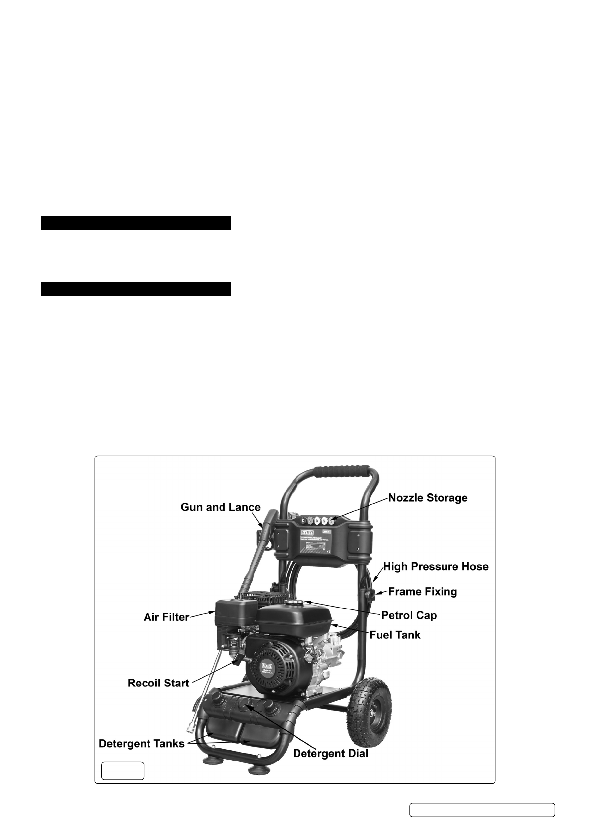
5.4.3. Pour two types of detergents into separate detergent tanks (fig.1). It is recommended to have one detergent tank filled with all-purpose
detergent, and the other filled with a more specific cleaning detergent, depending on the surface to be cleaned.
5.4.4. The liquid detergent will be mixed with water automatically, and discharged through the detergent nozzle at a low pressure.
5.4.5. Use the detergent dial (fig.1) to control the type and amount of detergent used using the scale as reference.
5.4.6. Set the detergent dial to OFF position in order to shut off detergent supply.
5.4.7. Allow detergent to remain on the surface for a short time before rinsing. DO NOT allow detergent to dry on the surface.
5.5. SHUTTING DOWN AND CLEANING UP
5.5.1. Skip step 5.5.2 if you are not using detergent.
5.5.2. After cleaning with detergent, fill the detergent tank with clean water. Spray water at a low pressure for one minute, so that all detergent
is flushed out of the system.
5.5.3. Stop the engine (→ Section 5.3 Shut Down Procedure).
5.5.4. Turn off the water supply and disconnect the water supply from the water inlet.
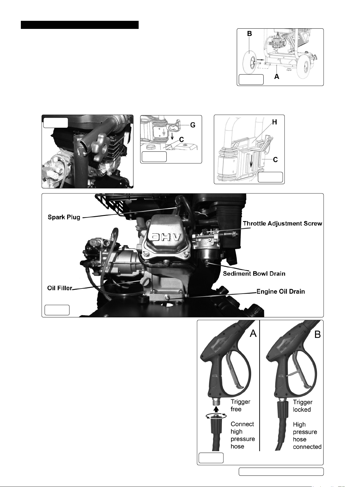
5.5.5. Point spray gun in safe direction, push trigger lock, and squeeze spray gun trigger to relieve retained high water pressure. Engage the
trigger safety lock (fig.7) on the spray gun.
5.5.6. Disconnect the garden hose from the pump.
5.5.7. Disconnect the pressure hose from the pump and pressure gun for storage. For long-term storage instructions, see section 7.8.
5.5.8. Rewind the pressure hose and attach it to the hose hook.
5.5.9. Disconnect the gun and wand, then insert them into the upper gun holder.
5.5.10. Fold the handle and store.
NOTE: After turning off the machine, wait for 20 minutes to prevent plastic parts from being burned by muffler, then fold the handle.
5.6. TRANSIT.
5.6.1. In the upright position the washer stands on four feet and the two wheels are off the ground. The front feet have suckers attached which
help to eliminate creep. The rear feet are out of sight between the wheels. To move the unit tip it backwards on the rear feet until the
wheels make contact with the ground. Keep the unit well tipped back as you move it.
5.7. ADDING/CHECKING OIL
IMPORTANT Oil has been drained for shipping. Failure to fill engine with oil before starting engine
will result in permanent damage and will void engine warranty.
WARNING! Always check the oil level before starting the engine, making sure the pressure
washer is on a level surface.
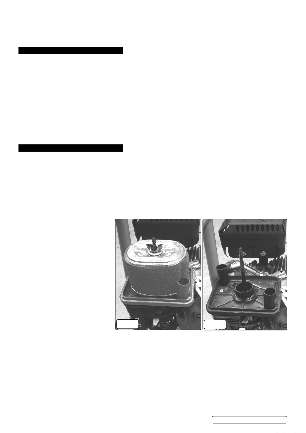
5.7.1. Remove oil tank dipstick (fig.8) and wipe it with a clean cloth.
5.7.2. Replace and retighten the dipstick.
5.7.3. Remove the dipstick again and check the oil level. It should be at the top of the full indicator on
the dipstick.
5.7.4. If low, add oil slowly into the oil tank. DO NOT overfill. After adding oil, wait one minute and then
recheck the oil level.
5.7.5. Replace and retighten the dipstick.
NOTE: When adding oil, use oil funnel.
5.7.6. Check the pump oil level by removing the pump filler cap (fig.8). The pump should be topped
up with 10w-30oil (the oil capacity of the pump is 0.5ltr).
5.8. ADDING FUEL
9Fill the fuel tank outdoors or in well-ventilated areas.
9Make sure there is enough fuel in the fuel tank before operating the pressure washer.
9 Use only clean, fresh, unleaded fuel. Use a minimum of 87octane/87 AKI (91 RON).
9 Keep fuel away from sparks, open ames, pilot lights, heat, and other ignition sources.
9 Check fuel hoses, tank, caps, and ttings frequently for cracks or leaks. Replace if necessary.
9 If fuel spills, wait until it evaporates before starting engine.
8DO NOT use old petrol, and DO NOT mix oil with petrol.
g.10
g.11
Original Language Version
© Jack Sealey Limited PWM2500.V2 Issue 1 29/11/19

5.8.1. Stop the engine (→ Section 5.3 Shut Down Procedure) and let it cool at least two minutes before removing the fuel tank cap (fig.1).
5.8.2. Clean the fuel cap area of dirt and debris. Remove the fuel tank cap and make sure the fuel lter is in place.
5.8.3. Fill the fuel tank (fig.1) with fuel. Never overll the fuel tank. Fill tank to no more than ½″ (13 mm) below the bottom of the ller neck
to provide space for expansion caused by the engine heat.
5.8.4. Replace the fuel tank cap.
6. MAINTENANCE - WASHER
WARNING! Maintenance should only be performed with the engine turned off and the unit disconnected from the mains water supply.
6.1. WINTER STORAGE
6.1.1. Fill the pump with an antifreeze mixture before storing in a frost free, safe, dry area for the winter. Introduce the antifreeze by the following
method.
1. Shut off the water supply and disconnect the supply hose. Relieve pressure within the pump by squeezing the gun trigger. Remove the
high pressure hose and let all water drain from it. Hold gun/lance with nozzle downwards and pull trigger until all water has drained out.
2. Disconnect the ignition lead from the spark plug.
3. Connect a short length of garden hose to the water inlet and using a funnel pour an antifreeze mixture into it.
4. Pull the recoil starter several times to circulate the antifreeze through the pump. Continue to add antifreeze and pull the recoil until
antifreeze is expelled from the pump.
6.2. CLEANING WATER INLET FILTER
WARNING! DO NOT operate this pressure washer without the water inlet lter in place, as deposits could build up internally and
affect the functioning of the unit.
6.2.1. This pressure washer is equipped with a water inlet lter.
6.2.2. The water inlet lter must be kept clean at all times, otherwise it can restrict the water ow to the pump unit and damage it.
6.2.3. Remove the quick-connect coupler from the water inlet, then remove and clean the water inlet lter.
7. MAINTENANCE - ENGINE
7.1. Change engine oil after the first 8 hours of operation. After that, it should be replaced every 100 hours or every six months. Change oil
more often if engine is operated under heavy load, or in high ambient air temperatures. During normal operation, partially burned fuel,
small particles of metal from the cylinder walls, pistons, bearings and combustion deposits will gradually contaminate the oil. If the oil is
not changed regularly, these foreign particles can cause increased friction and a grinding action which shortens the life of the engine.
Fresh oil also assists in cooling. Old oil gradually becomes thick and loses its cooling ability as well as its lubricating qualities.
7.2. CHECKING THE OIL LEVEL. Ensure the unit is on a level surface.
7.2.1. Unscrew the dipstick and wipe it clean of oil. Note that the maximum oil level should be just below the opening of the filler neck.
7.2.2. Check the oil level by seating the dipstick into the hole without screwing it in. If there is no oil on the dipstick when it is removed the level
is too low and should be topped up immediately with an SAE10W - 30 oil.
7.2.3. Top up oil if necessary and recheck level.
7.2.4. Screw dipstick fully home to seal oil fill hole.
NOTE: The engine is fitted with a low oil sensor which will automatically shut the engine down in a low oil situation. The sensor may also operate
if the unit is not on a level surface.
7.3. DRAINING ENGINE OIL
7.3.1. The engine oil should be replaced after
the first 8 hours of operation, or after the
first month of use. After that, it should be
replaced every 100 hours or every six
months.
7.3.2. To drain the engine oil:
1. Loosen the oil tank dipstick (fig.8).
2. Place an oil container underneath the
opening on the mainframe.
3. Remove the hex (fig.6) screw and
drain the oil.
4. Once the oil has been completely
drained, retighten the hex screw
(fig.6) and oil tank dipstick.
7.4. CHECKING AIR FILTER
IMPORTANT:Clean air filter (fig.1)
element after every 50 hours of use (every
10 hours under dusty conditions). Wash in
high flashpoint solvent, squeeze dry,
dip in clean engine oil, and squeeze out
excess oil.
7.4.1. To access the air filter element unscrew and remove the wing nut on the top of the cover. Lift the air filter cover off its threaded
mounting rod (fig.12).
7.4.2. Remove the foam filter (fig.13) from the air intake base moulding.
7.4.3. Wash the foam element with a household detergent or a high flash-point solvent and squeeze dry. When the element is thoroughly dry soak
it in clean engine oil. Squeeze out any excess oil, fit back over the air intake base moulding.
7.4.4. Place the air filter cover onto the threaded rod and secure with the wing nut.
7.4.5. The foam element should be replaced after every 300 hours of service.
g.12 g.13
Original Language Version
© Jack Sealey Limited PWM2500.V2 Issue 1 29/11/19

7.5. INSPECTING, REPLACING OR CLEANING THE SPARK PLUG
NOTE: The spark plug should be checked after every 100 hours of operation or every six
months.
7.5.1. To replace or clean the spark plug:
1. Disconnect the spark plug wire by pulling it off the spark plug.
2. Using provided spark plug wrench (fig.15.J), remove the spark plug by
turning it counter-clockwise. If there is a carbon sediment build-up, remove it.
If there is too much carbon sediment, replace the spark plug.
3. Check the gap with a wire gauge. If necessary, reset the gap to 0.7-0.8 mm (fig.14).
Install and tighten the spark plug to the recommended torque – 180 lb.·in (20 Nm).
4. Reinstall the spark plug wire and protection cage in reverse order.
NOTE: In some areas, local law requires using a resistor spark plug to suppress ignition
signals. If this engine was originally equipped with a resistor spark plug,
use the same type for replacement.
7.6. CLEANING THE CARBURETTOR FIG.16
7.6.1. To clean the carburettor:
1. Screw down the bolt on the bottom of carburettor with wrench.
2. Push the float up four to five times, then clean sediment cup with fuel.
NOTE: Put the sediment cup back. Be careful not to miss the O ring.
7.7. CLEANING THE SPRAY TIPS FIG. 17
WARNING! Clogging of the spray tip increases the
water pressure and might damage the pump unit .
7.7.1. Clean the spray tip by carefully inserting the provided
spray tip cleaner, or a thin, sharp object (e.g.,
paper clip) into the tip to remove deposits (fig.17).
7.8. PUMP WINTERIZATION AND LONG TERM
STORAGE
7.8.1. STEP 1: ENGINE STORAGE. If the unit is not to be used for more than one month the following
procedure should be followed.
1. Top-up engine oil to maximum.
2. Drain petrol from the fuel tank, fuel line, fuel tap and carburettor.
3. Pour one teaspoon of engine oil through the spark plug hole, pull the recoil starter several times and replace the spark plug. Then pull
the starter slowly until an increase in pressure is felt indicating that the piston has commenced its compression stroke and leave it in this
position. This closes both the intake and exhaust valves and prevents the inside of the cylinder from rusting.
7.8.2. STEP 2: PROTECT FUEL SYSTEM
FUEL ADDITIVE:
Fuel can become stale when stored for over 30 days. Stale fuel causes acid and gum deposits to form in the fuel system or on essential
carburettor parts. Please use fuel stabilizer to keep fuel fresh. Run the engine for 2 minutes to circulate the stabilizer throughout the fuel
system before storage.
DRAIN FUEL FIG 6:
If fuel in the engine has not been treated with a fuel stabilizer, it must be drained into an approved container. Run the engine until it
stops from lack of fuel. Remove the hex screw from the carburettor then drain the fuel from the tank, carburettor, and tube. Screw the
carburettor drain hex screw back once the fuel has been completely drained.
7.8.3. STEP 3: CHANGE OIL
WARNING! Petrol is extremely ammable and potentially explosive. DO NOT perform maintenance on petrol associated components
where there is any source of ignition present such as cigarettes, sparks, naked ame or hot surfaces.
7.8.4. While engine is still warm, drain oil from crankcase. Remove the hex screw from the crankcase (fig.6). Drain the oil to a container. Refill
with recommended grade oil (SAE 10W-30).
IMPORTANT:
• If the pressure washer is to be stored with fuel in the fuel tank and carburettor, it is important to reduce the hazard of fuel vapour ignition.
• Select a well-ventilated storage area away from any appliance that operates with a flame, such as a furnace, water heater, or clothes
dryer. Also avoid any area with a spark-producing electric motor, or where power tools are operated.
• If possible, avoid storage areas with high humidity, this will promote rust and corrosion.
• Place the pressure washer on a level surface. Tilting can cause fuel or oil leakage.
7.9. MAINTENANCE SCHEDULE.
7.9.1. Before each use;
Check engine oil level.
Inspect the unit for evidence of oil and fuel leaks.
7.9.2. After the first 8 hours or 20 hours only;
Change the engine oil.
Check pump oil
Every 50 hours.
Change the engine oil.
7.9.3. Every 6 months or 100 hours;
Change the engine oil.
Check pump oil
Inspect and clean air filter.
Clean the deposit cup.
Clean spark plug and check gap.
7.9.4. Every 300 hours;
Replace air cleaner element.
Check valve clearances.
Check idling speed.
Clean spark plug and check gap.
Clean fuel tank fuel filter.
g.14
g.15
g.17 g.16
Original Language Version
© Jack Sealey Limited PWM2500.V2 Issue 1 29/11/19

8. TROUBLESHOOTING
PROBLEM POSSIBLE CAUSE SOLUTION
Engine
Engine doesn’t start
or is difcult to start
No fuel Fill the fuel tank with regular gasoline
Excess water pressure in pump or hose Release water pressure by squeezing trigger
on gun
Clogged carburettor Clean the carburettor. Refer to the instruction
manual
Carbon build-up on spark plug Clean the spark plug. Refer to the instruction
manual
Incorrect starting method Use correct starting method. Refer to the
instruction manual
Engine stops after
starting
Low oil or no fuel Check oil and fuel levels
Engine lacks power
Clogged air lter Clean or replace the air lter. Refer to the
instruction manual
Clogged carburettor Clean the carburettor. Refer to the instruction
manual
Carburettor leaks Carburettor is clogged Clean the carburettor. Refer to the instruction
manual
Starter rope doesn’t
recoil
Recoil mechanism is broken Contact your local Sealey Stockist
Engine sounds
abnormal or
overloaded
Clogged nozzle Clean nozzle with tip cleaner
Pressure is too high Contact your local Sealey Stockist
Pump
No pressure, low
pressure
Nozzle tip not attached Attach required nozzle tip
Water supply tap closed Turn on tap. Ensure there are no kinks or
blockage in hose
Water supply pressure is low Ensure tap is fully opened. Check to make
sure water supply is to spec
Inlet water lter is clogged Clean the water lter. Refer to the instruction
manual
Air in pump Squeeze trigger to release the air in pump
when the machine is running
Clogged check valve Contact your local Sealey Stockist
Damaged pump Contact your local Sealey Stockist
Pressure too high Clogged nozzle Clean nozzle with tip cleaner
Water or oil leaks out
of pump
Damaged seal ring Contact your local Sealey Stockist
Cold water keeps
draining out of
thermal relief valve
Defective thermal relief valve Contact your local Sealey Stockist
Accessories &
Connections
No intake of
detergent
The detergent siphon tube is not connected Connect detergent siphon tube properly.
Refer to the instruction manual
Damaged detergent siphon tube Replace the detergent siphon tube
Wrong nozzle Use black nozzle when applying detergent.
Refer to the instruction manual
Detergent adjustment knob set to wrong
position
Check adjustment knob. Refer to the
instruction manual
Clogged nozzle Clean nozzle
Clogged pump detergent siphon tting Detach the detergent siphon tube and clean
the tting with tip cleaner
Detergent is too thick. Clogged detergent
lter
Use only detergent approved for use with
pressure washer
The trigger can’t be
squeezed
Safety lock is open Close the safety lock. Refer to the instruction
manual
There is water
leakage at joints/
connections on gun,
hose and/or pump
Damaged seal ring Change with new O-ring.
High pressure hose
can’t be connected to
pump or gun
The O rings are not lubricated Put lubricating oil or water on the O rings
Original Language Version
© Jack Sealey Limited PWM2500.V2 Issue 1 29/11/19

Sealey Group, Kempson Way, Suffolk Business Park, Bury St Edmunds, Suffolk. IP32 7AR
01284 757500 01284 703534 sales@sealey.co.uk www.sealey.co.uk
ENVIRONMENT PROTECTION
Recycle unwanted materials instead of disposing of them as waste. All tools, accessories and packaging should be sorted, taken to
a recycling centre and disposed of in a manner which is compatible with the environment. When the product becomes completely
unserviceable and requires disposal, drain any fluids (if applicable) into approved containers and dispose of the product and fluids
according to local regulations.
WASTE ELECTRICAL AND ELECTRONIC EQUIPMENT REGULATIONS (WEEE)
When this product is no longer required, or has reached the end of it’s useful life, please dispose of it in an environmentally friendly way,
in accordance with local waste regulations.
Note: It is our policy to continually improve products and as such we reserve the right to alter data, specifications and component parts without prior
notice.
Important: No Liability is accepted for incorrect use of this product.
Warranty: Guarantee is 12 months from purchase date, proof of which is required for any claim.
Original Language Version
© Jack Sealey Limited PWM2500.V2 Issue 1 29/11/19
Table of contents
Other Sealey Pressure Washer manuals

Sealey
Sealey PW1601 User manual

Sealey
Sealey PWM2500SP.V2 User manual

Sealey
Sealey PW2000PA User manual

Sealey
Sealey PC1750 User manual

Sealey
Sealey PW2012R User manual

Sealey
Sealey PW1750 Firmware update

Sealey
Sealey POWER PRODUCTS PC2701 User manual

Sealey
Sealey PC2351 User manual

Sealey
Sealey PW1860 User manual

Sealey
Sealey Power Products PC3401 User manual

Sealey
Sealey PWM1300.V2 User manual

Sealey
Sealey PW2512 User manual

Sealey
Sealey PW1500 User manual

Sealey
Sealey PW2200 User manual

Sealey
Sealey PC2950.V5 User manual

Sealey
Sealey PWTF2200 User manual

Sealey
Sealey PCM2500.V2 User manual

Sealey
Sealey PW5000 User manual

Sealey
Sealey PCM1300.V2 User manual

Sealey
Sealey PCM1500.V2 User manual