RIDGID 1210 User manual

Oil-less Threading
Machine
1"Capacity
•Français – 17
•Castellano – pág. 35
1210 Operator’s Manual
WARNING!
Read this Operator’s Manual
carefully before using this
tool. Failure to understand
and follow the contents of
this manual may result in
electrical shock, fire and/or
serious personal injury.

Table of Contents
Recording Form for Machine Model and Serial Number............................................................................................1
Safety Symbols..............................................................................................................................................................2
General Power Tool Safety Warnings
Work Area Safety ........................................................................................................................................................2
Electrical Safety...........................................................................................................................................................2
Personal Safety ...........................................................................................................................................................3
Power Tool Use and Care ...........................................................................................................................................3
Service ........................................................................................................................................................................3
Specific Safety Information
Threading Machine Safety ..........................................................................................................................................3
Description, Specifications and Standard Equipment
Description ..................................................................................................................................................................4
Specifications ..............................................................................................................................................................4
Standard Equipment....................................................................................................................................................4
Pre-Operation Inspection..............................................................................................................................................5
Machine and Work Area Set-Up ...................................................................................................................................6
Installing Dies and Adjusting For Size In No. 610 Quick-Opening Die Head ..............................................................8
Operating Instructions ..................................................................................................................................................9
Cutting Pipe with No. 354 Cutter ...............................................................................................................................10
Reaming Pipe with No. 334 Reamer .........................................................................................................................10
Threading Pipe with No. 610 Die Head .....................................................................................................................11
Removing Pipe From Machine ..................................................................................................................................11
Inspecting Threads and Adjusting Thread Size.........................................................................................................11
Preparing Machine for Transport...............................................................................................................................12
Maintenance Instructions
Cleaning ....................................................................................................................................................................12
Lubrication.................................................................................................................................................................12
Replacing Cutter Wheel ............................................................................................................................................12
Replacing Jaw Inserts ...............................................................................................................................................12
Replacing Carbon Brushes .......................................................................................................................................13
Accessories .................................................................................................................................................................14
Machine Storage..........................................................................................................................................................14
Cutting Fluid Information............................................................................................................................................14
Service and Repair ......................................................................................................................................................14
Disposal........................................................................................................................................................................14
Troubleshooting ..........................................................................................................................................................15
Wiring Diagram ............................................................................................................................................................16
Lifetime Warranty..........................................................................................................................................Back Cover
Ridge Tool Companyii
1210 Oil-less Threading Machine

1210
Oil-less Threading Machine
1210
1210 Oil-less Threading Machine
Record Serial Number below and retain product serial number which is located on nameplate.
Serial
No.

Ridge Tool Company2
1210 Oil-less Threading Machine
General Power Tool
Safety Warnings*
WARNING
Read all safety warnings and instructions. Failure to follow
the warnings and instructions listed below may result in
electric shock, fire, and/or serious personal injury.
SAVE ALL WARNINGS AND INSTRUCTIONS
FOR FUTURE REFERENCE!
The term "power tool" in all of the warnings listed below
refers to your mains-operated (corded) power tool or bat-
tery-operated (cordless) power tool.
Work Area Safety
•Keep your work area clean and well lit. Cluttered or
dark areas invite accidents.
•Do not operate tools in explosive atmospheres,
such as in the presence of flammable liquids,
gases, or dust. Power tools create sparks which may
ignite the dust or fumes.
•Keep children and by-standers away while oper-
ating a power tool. Distractions can cause you to
lose control.
Electrical Safety
•Power tool plugs must match the outlet. Never
modify the plug in any way. Do not use any adapter
plugs with earthed (grounded) power tools. Un-
modified plugs and matching outlets will reduce risk
of electric shock.
•Avoid body contact with earthed or grounded sur-
faces, such as pipes, radiators, ranges and refrig-
erators. There is an increased risk of electrical shock if
your body is earthed or grounded.
•Do not abuse the cord. Never use the cord for car-
rying, pulling or unplugging the power tool. Keep
cord away from heat, oil, sharp edges or moving
parts. Damaged or entangled cords increase the risk of
electrical shock.
Safety Symbols
In this operator’s manual and on the product, safety symbols and signal words are used to communicate important safety
information. This section is provided to improve understanding of these signal words and symbols.
This is the safety alert symbol. It is used to alert you to potential personal injury hazards. Obey all safety messages that follow this
symbol to avoid possible injury or death.
DANGER indicates a hazardous situation which, if not avoided, will result in death or serious injury.
WARNING indicates a hazardous situation which, if not avoided, could result in death or serious injury.
CAUTION indicates a hazardous situation which, if not avoided, could result in minor or moderate injury.
NOTICE indicates information that relates to the protection of property.
This symbol means read the operator’s manual carefully before using the equipment. The operator’s manual contains important
information on the safe and proper operation of the equipment.
This symbol means always wear safety glasses with side shields or goggles when handling or using this equipment to reduce
the risk of eye injury.
This symbol indicates the risk of fingers, hands, clothes and other objects catching on or between gears or other rotating parts
and causing crushing injuries.
This symbol indicates the risk of electrical shock.
This symbol means always use a foot switch when using a threading machine/power drive to reduce the risk of injury.
This symbol means do not wear gloves while operating this machine to reduce the risk of entanglement.
This symbol indicates the risk of machine tipping, causing striking or crushing injuries.
This symbol indicates the risk of fingers, legs, clothes and other objects catching and/or wrapping on rotating shafts causing
crushing or striking injuries.
* The text used in the General Safety Rule section of this manual is verbatim, as required, from the applicable UL/CSA 60745-1 3rd edition standard. This sec-
tion contains general safety practices for many different types of power tools. Not every precaution applies to every tool, and some do not apply to this tool.
NOTICE
DANGER
WARNING
CAUTION

•When operating a tool outdoors, use an extension
cord suitable for outdoor use. Use of a cord suitable
for outdoor use reduces the risk of electrical shock.
•If operating a power tool in a damp location is un-
avoidable, use a ground fault circuit interrupter
(GFCI) protected supply. Use of an GFCI reduces the
risk of electric shock.
Personal Safety
•Stay alert, watch what you are doing and use com-
mon sense when operating a power tool. Do not
use power tool while you are tired or under the in-
fluence of drugs, alcohol, or medication. A moment
of inattention while operating power tools may result in
serious personal injury.
•Use personal protective equipment. Always wear
eye protection. Protective equipment such as dust
mask, non-skid safety shoes, hard hat, or hearing pro-
tection used for appropriate conditions will reduce
personal injuries.
•Prevent unintentional starting. Ensure the switch is
in the off-position before connecting to power
source and/or battery pack, picking up or carrying
the tool. Carrying power tools with your finger on the
switch or energizing power tools that have the switch
ON invites accidents.
•Remove any adjusting key or wrench before turn-
ing the power tool ON. A wrench or a key left attached
to a rotating part of the power tool may result in per-
sonal injury.
•Do not overreach. Keep proper footing and balance
at all times. This enables better control of the power
tool in unexpected situations.
•Dress properly. Do not wear loose clothing or jew-
elry. Keep your hair and clothing away from moving
parts. Loose clothes, jewelry, or long hair can be
caught in moving parts.
•If devices are provided for the connection of dust
extraction and collection facilities, ensure these are
connected and properly used. Use of dust collection
can reduce dust-related hazards.
Power Tool Use and Care
•Do not force the power tool. Use the correct power
tool for your application. The correct power tool will
do the job better and safer at the rate for which it is de-
signed.
•Do not use power tool if the switch does not turn
it ON and OFF. Any power tool that cannot be con-
Ridge Tool Company 3
1210 Oil-less Threading Machine
trolled with the switch is dangerous and must be re-
paired.
•Disconnect the plug from the power source and/or
the battery pack from the power tool before making
any adjustments, changing accessories, or storing
power tools. Such preventive safety measures re-
duce the risk of starting the power tool accidentally.
•Store idle power tools out of the reach of children
and do not allow persons unfamiliar with the power
tool or these instructions to operate the tool. Power
tools are dangerous in the hands of untrained users.
•Maintain power tools. Check for misalignment or
binding of moving parts, breakage of parts and
any other condition that may affect the power
tool’s operation. If damaged, have the tool repaired
before use. Many accidents are caused by poorly
maintained power tools.
•Keep cutting tools sharp and clean. Properly main-
tained cutting tools with sharp cutting edges are less
likely to bind and are easier to control.
•Keep handles dry and clean; free from oil and
grease. Allow for better control of the tool.
Service
•Have your power tool serviced by a qualified repair
person using only identical replacement parts.
This will ensure that the safety of the power tool is
maintained.
Specific Safety Information
WARNING
This section contains important safety informa-
tion that is specific to this tool.
Read these precautions carefully before using the
1210 Oil-less Threading Machine to reduce the
risk of serious personal injury.
SAVE THESE INSTRUCTIONS!
Contact Ridge Tool Technical Service Department at (800)
questions.
Threading Machine Safety
•Guard or barricade minimum of one (1) metre a-
round the area when work piece extends beyond
machine. A guard or barricade that provides a clear-
ance around the work piece will reduce the risk of
entanglement.

Ridge Tool Company4
•Never reach into the machine chuck or centering
head. This will reduce the risk of entanglement.
Description, Specifications and
Standard Equipment
Description
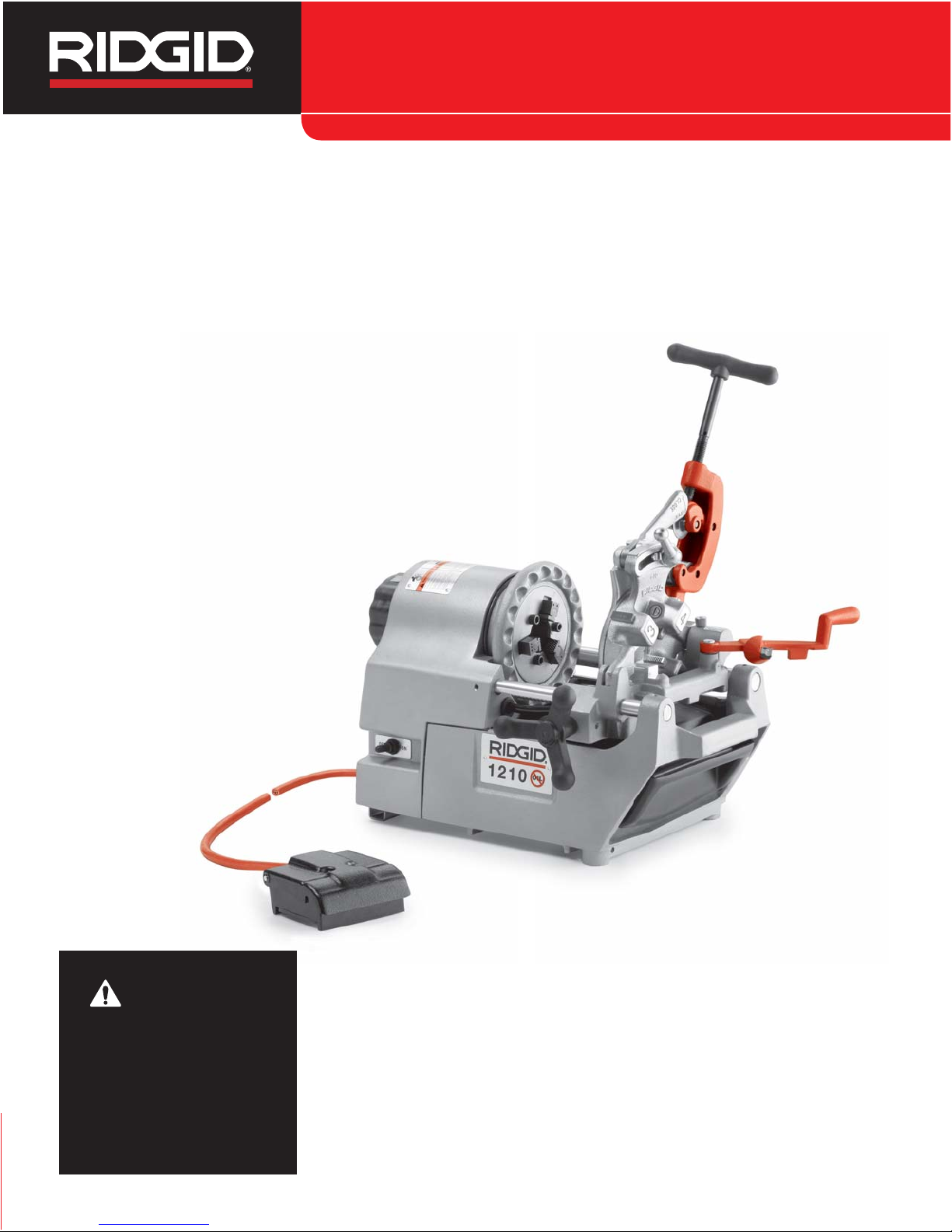
The RIDGID®Model 1210 Oil-less Threading Machine is
an electric motor-driven machine that centers and chucks
pipe and rotates it while cutting, reaming and threading
operations are performed. Threading dies are mounted
in a quick-opening die head. An integral coolant system
meters a specially formulated thread cutting fluid onto the
thread to reduce the temperature of the workpiece and lu-
bricate it during the threading operation.
Specifications
Threading Capacity .......Pipe 1/2" through 1"
Cut-Off Capacity............Pipe 1/2" through 1"
Operating Speed ...........25 RPM (No Load)
Motor:
Type ............................Universal
Volts ............................115V Single Phase AC
50/60 HZ
Amps ...........................6.4
Controls.........................ON/OFF Toggle Switch and
ON/OFF Foot Switch
Chuck ............................Hammer-Style with Replace-
able Inserts; Cam Action Rear
Centering Device
Coolant System.............16 Oz. Integral Coolant
Reservoir with Gerotor Pump
Weight ...........................59 lbs.
The 1210 Threading Machine is protected under U.S.
and international patents, including U. S. patent 5,826,469.
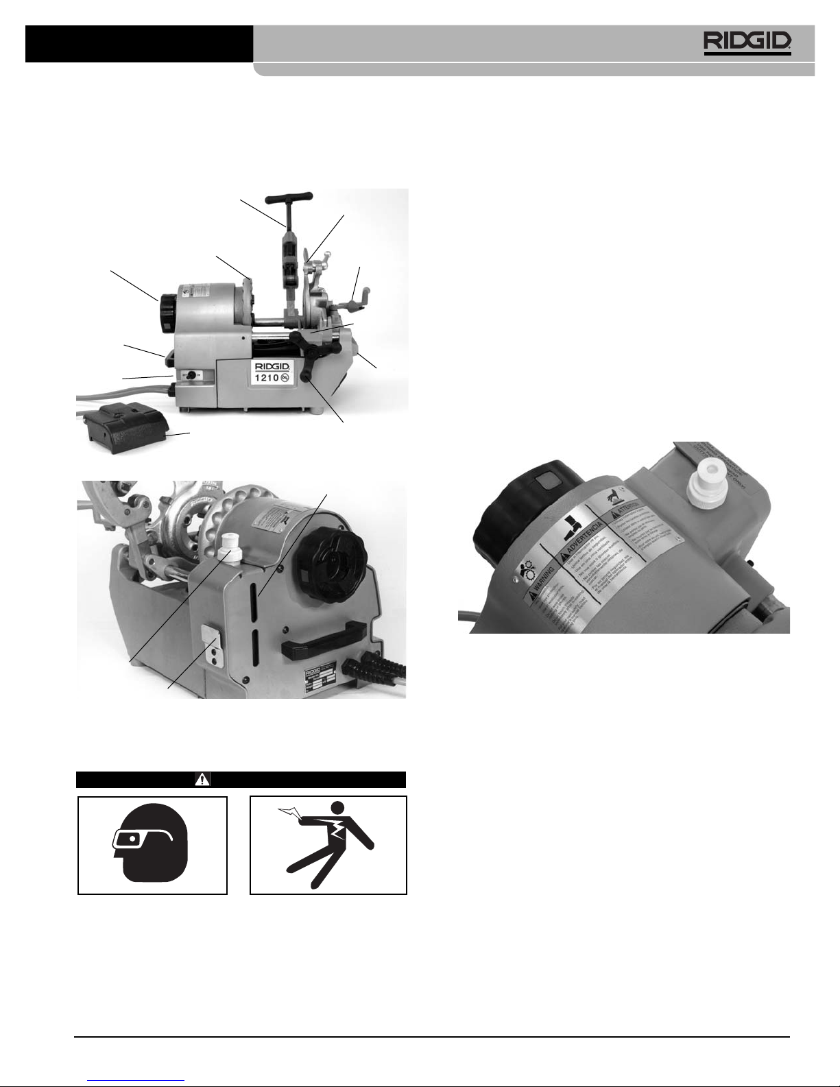
Standard Equipment
(Figure 1)
• Model 610 Quick-Opening Die Head, 1/2" – 1" NPT
•1/2"–
3/4" Oil-less Gold NPT Dies
• 1" Oil-less Gold NPT Dies
• Model 334 Blade-Type Reamer
• Model 354 Roll-Type, Self-Centering Cutter
• 1 Quart RIDGID Thread Cutting Coolant Fluid
Selection of appropriate materials and joining
methods is the responsibility of the system designer
1210 Oil-less Threading Machine
•Follow instructions on proper use of this machine.
Do not use for other purposes such as drilling
holes or turning winches. Other uses or modifying
this power drive for other applications may increase the
risk of serious injury.
•Do not use this machine to install or remove fit-
tings, it is not an intended use of the machine.
This practice could lead to trapping, entanglement and
loss of control.
•Secure machine to bench or stand. Support long
heavy pipe with pipe supports. This practice will
prevent tipping.
•Do not wear gloves or loose clothing when oper-
ating machine. Keep sleeves and jackets buttoned.
Do not reach across the machine or pipe. Clothing
can be caught by the pipe or machine resulting in en-
tanglement.
•While operating the machine, stand on the side
where the operator’s controls are located. Operating
the machine from this side eliminates need to reach
over the machine.
•Keep hands away from rotating pipe and fittings.
Stop the machine before wiping pipe threads or
screwing on fittings. Allow the machine to come to
a complete stop before touching the pipe. This
practice will reduce the chance of entanglement in ro-
tating parts.
•Keep covers in place. Do not operate the machine
with covers removed. Exposing moving parts in-
creases the probability of entanglement.
•Keep all electrical connections dry and off the
ground. Do not touch plugs or tool with wet hands.
These precautions will reduce the risk of electrical
shock.
•Keep floor dry and free of slippery materials such
as oil. Slippery floors invite accidents.
•Do not use this machine if the foot switch is broken
or missing. Foot switch is a safety device that provides
better control by letting you shut off the motor in various
emergency situations by removing your foot from the
switch. For example: if clothing should become caught
in the machine, the high torque will continue pulling you
into the machine. The clothing itself can bind around
your arm or other body parts with enough force to
crush or break bones.
•One person must control the work process, thread-
ing machine operation and foot switch. Only the
operator should be in the work area when the ma-
chine is running. This helps reduce the risk of injury.
NOTICE

in the OFF position and that the power cord is un-
plugged.
2. Clean any oil, grease or dirt from the threading ma-
chine, including the handles and controls. This allows
better inspection of the machine and helps prevent the
machine or control from slipping from your grip during
use. If necessary, clean the speed chuck inserts with
a wire brush. Remove metal shavings and chips
from the die head and chip tray.
3. Inspect the power cord and plug for damage or mod-
ification, such as cuts or a missing grounding plug.
4. Make sure that the foot switch
(See Figure 1A)
is at-
tached to the machine and that it and the cord are in
good condition. Press the foot switch treadle and
confirm that it cycles smoothly and does not stick.
5. Check that the warning label is firmly attached and
readable.
See Figure 2.
Figure 2 – Warning Label
6. Inspect the threading machine for any broken, missing,
misarranged or binding parts or any other condition
that may prevent the safe and normal operation of the
machine.
7. Inspect the cutting edges of the dies, cutter wheel and
reamer for wear, deformation, chips or other issues.
Dull or damaged cutting tools increase the amount of
force required, produce poorer quality threads and in-
crease the risk of injury.
8. If necessary, lubricate the threading machine per
the maintenance instructions. Wipe any excess lu-
bricant from the machine.
9. If any issues are found during the inspection of the
threading machine, do not use the machine until
those issues have been corrected.
10. Inspect and maintain any other equipment being
used per its instructions to make it is sure functioning
properly.
and/or installer. Before any installation is attempted, care-
ful evaluation of the specific service environment, including
chemical environment and service temperature should be
completed.
Figure 1A – 1210 Threading Machine
Figure 1B – 1210 Threading Machine
Pre-Operation Inspection
WARNING
Before each use, inspect your threading machine
and correct any problems to reduce the risk of se-
rious injury from electrical shock, crushing injuries
and other causes and prevent threading machine
damage.
1. Make sure the threading machine ON/OFF switch is
Ridge Tool Company 5
1210 Oil-less Threading Machine
Rear Centering
Device
Chuck
Handwheel
Carrying
Handle
Carrying
Handle
No. 354
Cutter Model 610
Die Head
No. 334
Reamer
Foot
Switch
Carriage
Handwheel
ON/OFF
Switch
Foot Switch Clip
Reservoir
Vent Cap
Coolant Level
Sight Glass
Carriage

Machine and Work Area Set-Up
WARNING
Set up the threading machine and the work area
according to these procedures to reduce the risk
of injury from electric shock, machine tipping,
entanglement, crushing and other causes, and to
help prevent threading machine damage.
Do not use a threading machine without a properly
operating foot switch. Never block a foot switch in
the “ON” position so that it does not control the ma-
chine. A foot switch provides better control by
letting you shut off the machine motor by removing
your foot. If entanglement should occur and power
is maintained to the motor, you will be pulled into
the machine. This machine has high torque and
can cause clothing to bind around your arm or
other body parts with enough force to crush or
break bones or cause striking or other injuries.
1. Locate a work area that has:
• Adequate lighting.
• No flammable liquids, vapors or dust that may ignite.
The threading machine is not explosion proof, and
can cause sparks.
• Clear, level, stable, dry location for all of the equip-
ment and the operator.
• Good ventilation. Do not use extensively in small,
enclosed areas.
• Properly grounded electrical outlet of the proper
voltage. A three prong or GFCI outlet may not be
properly grounded. If in doubt, have outlet in-
spected by a licensed electrician.
• Clear path to the electrical outlet away from things
that can damage the power cord.
• Clear path to transport the equipment to the work
area.
2. Clean the work area before setting up any equip-
ment. Wipe up any oil or liquids.
3. Inspect the pipe to be threaded and associated fittings
and confirm that the 1210 Threading Machine is a cor-
rect tool for the job. The 1210 Threading Machine is
designed to cut, ream and thread schedule 40 and
heavier wall steel pipe in 1/2" to 1" sizes. The 1210
Threading Machine can thread pipe as short as 41/2".
Threading dies are available for both NPT and BSPT
thread forms. Do not use to thread anything other
than straight pipe. Do not thread pipe with fittings or
Ridge Tool Company6
1210 Oil-less Threading Machine
other attachments. These increase the risk of entan-
glement injuries.
Threading equipment for other applications can
be found in the Ridge Tool catalog, on line at
www.RIDGID.com, or by calling Ridge Tool Tech-
nical Services at 800-519-3456.
4. Confirm that the equipment to be used has been
properly inspected.
5. Transport equipment to work area along a clear path.
See “Preparing Machine For Transport” for machine
preparation. Use carrying handles to grip machine and
be aware that the 1210 Threading Machine weighs 59
pounds. Use care moving equipment, especially up
and down stairs, and be aware of possible slip haz-
ards.
6. Place the threading machine on a solid, level and sta-
ble working surface at least as large as machine
footprint approximately waist height, or if using the 120
Stand (not included) for the 1210 threading machine,
set up as follows.
• Pivot the two outside legs of the 120 Stand outward
until the plunger pins lock into place, (
See Figure 3)
and place in work area.
• Grasp the front and rear carrying handles of the
threading machine and place it on the 120 Stand,
be sure to place the base of the threading ma-
chine over the guide pins on the top of the 120
stand as shown in
Figure 3
. The center leg of
the stand lines up under the rear centering device
of the machine.
• Insert the retaining pin into the base of the thread-
ing machine
(as shown in Figure 4, inset)
. Retaining
pin helps to prevent tipping of the threading ma-
chine during use.
• Check that the machine and stand are stable
.
Figure 3 – Model 120 Stand in OPEN Position.
Center Leg
Outside Legs
Plunger Pins
Guide Pins

connections dry and off the ground. If the power cord
is not long enough use an extension cord that:
• Is in good condition.
• Has a three prong plug like on the threading ma-
chine.
• Is rated for outdoor use and contains a W or W-A
in the cord designation (e.g. SOW).
• Has sufficient wire size (16 AWG for 50' or less, 14
AWG for 50' – 100' long). Undersized wires can
overheat, causing fire or other damage.
15. Check the threading machine for proper operation.
• Move the ON/OFF switch to the ON position. Press
and release the foot switch. Confirm that the chuck
rotates counter-clockwise when viewed from the
tool side of the threading machine. If the threading
machine does not rotate in the correct direction,
or the foot switch does not control the machine op-
eration, do not use the machine until it has been
repaired.
• Depress and hold the foot switch. Inspect the mov-
ing parts for misalignment, binding, odd noises or
any other unusual conditions. Release foot switch.
If any unusual conditions are found, do not use
the machine until it has been repaired.
16. Check the level of RIDGID Thread Cutting Coolant by
looking at the sight glass at the rear of the 1210
threading machine
(see Figure 5)
. If necessary, re-
move the reservoir cap and fill with coolant. The
reservoir holds approximately 16 ounces of coolant.
RIDGID Thread Cutting Coolant is engineered
for use with the 1210 Threading machine. It lubricates the
thread and cools the thread by evaporation. Use of other
fluids will void the 1210 Threading Machine warranty and
may damage the threading dies or cause poor quality
threads. RIDGID Thread Cutting Coolant should not be
used with any other threading equipment for the same rea-
sons. Do not dilute thread cutting coolant.
Figure 5 – Filling Coolant Reservoir
Figure 4 – 1210 Machine Mounted on Model 120 Stand
7. Uncoil the power cord and foot switch. Confirm that the
ON/OFF switch is in the OFF position.
8. Check that the correct dies are in the die head and are
properly set. If needed, install and/or adjust the dies in
the die head.
9. Swing the cutter, reamer and die head into the position
away from the operator.
10. If pipe will extend past the chip tray in the front of the
machine or more than 2' out of the rear of the machine
use, pipe stands to support the pipe and prevent the
pipe and threading machine from tipping or falling.
Place the pipe stands in line with machine chucks, ap-
proximately 1/3of the distance from the end of the
pipe to the machine. Longer pipe may need more
than one pipe stand. Only use pipe stands designed
for this purpose. Improper pipe supports or supporting
the pipe by hand can cause tipping or entanglement
injuries.
11. Set-up guards or barricades to create a minimum of
one meter (3 feet) of clearance around the threading
machine and pipe. This helps prevent non-operators
from accidentally contacting the machine or pipe and
causing tipping or becoming entangled in the rotating
parts.
12. Fully open the chucks of the threading machine.
13. Position the foot switch as shown in
Figure 10
, to
allow a proper operating position.
14. With the ON/OFF switch in the OFF position, run the
cord along the clear path. With dry hands plug the
power cord into the properly grounded outlet. Keep all
Ridge Tool Company 7
1210 Oil-less Threading Machine
Retaining Pin
NOTICE
Sight
Glass

Ridge Tool Company8
17. Pull the vent on the reservoir cap open
(Figure 6).
Do
not thread with the vent closed. This will reduce
coolant flow and could cause die chipping and poor
quality threads.
Figure 6 – Reservoir Vent Open
18. Move the die head down into the threading position.
Depress and hold the foot switch and look for coolant
flow between die 3 and 4 on the die head
(See Figure
7)
. It may take up to 10 seconds for the coolant to start
flowing if the die head has been off the machine or sat
for an extended time. Coolant should be dripping at a
rate of at least 1 drop per second. Too high a drip rate
wastes coolant, while too low a drip rate can cause die
chipping, poor quality thread and high thread temper-
atures.
19. To adjust the coolant drip rate, while depressing the
foot switch, use a flat blade screwdriver to turn the
needle pin on the die head
(see Figure 7)
. Clockwise
needle pin rotation decreases drip rate, while coun-
terclockwise rotation increases drip rate
Figure 7 – Adjusting Coolant Drip Rate
20. Move the die head away from the operator. Die head
position turns the coolant flow on and off while ma-
chine is running. To conserve coolant, only place die
head down in the threading position when threading or
transporting.
21. Move the ON/OFF switch to the OFF position, and
with dry hands unplug the machine.
Installing Dies and Adjusting For Size In
No. 610 Quick-Opening Die Head
The 610 quick-opening die head
(Figure 8)
uses one set
of dies for 1/2" and 3/4" threads and another set for 1"
threads. Dies are available for NPT and BSPT thread
forms.
The 610 Die Head is designed for use ONLY with the
1210 Threading Machine. This die head is not compati-
ble with any other RIDGID threading equipment. No
other RIDGID die heads will fit on the Model 1210
Threading Machine.
1. With machine unplugged, rotate the die head retaining
knob
(Figure 7)
on the carriage counterclockwise to
unlock the die head post. Remove the die head from
the carriage.
Figure 8 – No. 610 Quick-Opening Die Head
2. Lay die head on bench with numbers up.
3. Flip throwout lever to OPEN position.
4. Loosen clamp lever approximately three full turns.
5. Lift tongue of clamp lever washer up out of slot under
size bar. Slide throwout lever all the way to the end of
slot in the OVER direction on size bar (CHANGE
DIES arrow on rear of cam plate).
6. Remove dies from die head.
7. Insert new dies to indicator line on the dies.
See
Figure 9.
Die numbers 1 through 4 on the dies must
1210 Oil-less Threading Machine
Needle Pin,
Drip Rate
Adjustment Screw
-
+
Look For
Coolant
Flow Here
Die Head
Retaining
Knob
Index Line
Link
Throwout
Lever
Clamp Lever
Washer
Head
Clamp Lever
Size Bar
Cam Plate

pipe. To prevent entanglement crushing or strik-
ing injuries, allow machine to come to a complete
stop before touching the pipe or machine chucks.
Do not use this machine to make or break (tighten or
loosen) fittings. This can cause striking or crushing
injuries.
Do not use a threading machine without a properly
operating foot switch. Never block a foot switch in
the “ON” position so that it does not control the
threading machine. A foot switch provides better
control by letting you shut off the machine motor by
removing your foot. If entanglement should occur
and power is maintained to the motor, you will be
pulled into the machine. This machine has high
torque and can cause clothing to bind around your
arm or other body parts with enough force to crush
or break bones or cause striking or other injuries.
One person must control both the work process
and the foot switch. Do not operate with more than
one person. In case of entanglement, the operator
must be in control of the foot switch.
Follow operating instructions to reduce the risk of
injury from entanglement, striking, crushing and
other causes.
1. Inspect and set-up the machine and work area ac-
cording to this manual. Make sure that the work area
is free of by-standers and other distractions. The op-
erator should be the only person in the barricaded
area while the machine is being operated.
The cutter, reamer and die head should be away
from the operator, not in the operating position.
2. If needed, mark the pipe at the appropriate location. In-
sert the pipe to be worked into the threading machine
so that the area to be cut or end to be reamed or
threaded is approximately 4" from the front of the
chuck. If closer, the carriage may strike the machine
during the threading and damage the machine. Do not
reach into the chuck or centering device. Confirm that
pipe stands are properly placed.
3. Turn the rear centering head counterclockwise
(viewed from rear of machine) to close down onto
pipe. This improves pipe support and gives better
results.
4. Turn the speedchuck handwheel counterclockwise
(viewed from front of machine) to close down onto
pipe. Make sure that the pipe is centered in the inserts.
Use repeated and forceful counterclockwise spins of
the handwheel to secure the pipe in the speedchuck.
5. Assume a proper operating position to help main-
tain control of the machine and pipe
(See Figure 10)
.
• Stand on the ON/OFF switch side of the machine
with convenient access to the tools and ON/OFF
switch.
agree with those on the die head to make a correct
thread.
Figure 9 – Inserting Dies Into Die Head
8. Slide throwout lever back so that tongue of clamp
lever washer will drop in slot under size bar.
9. Adjust die head size bar until index line on link is
aligned with proper size mark on size bar. If oversize
or undersize threads are required, set the index line in
direction of OVER or UNDER size mark on size bar.
10. Tighten clamp lever.
11. Reinstall die head in machine, and position away
from operator.
12. Rotate the die head retaining knob on the carriage
clockwise until tight.
13. Perform a test cut to confirm thread size.
Operating Instructions
WARNING
Always wear eye protection. Wear steel toe foot-
wear to help protect from tipping tools and falling
pipe.
Do not wear gloves or loose clothing. Keep sleeves
and jackets buttoned. Loose clothing can become
entangled in rotating parts and cause crushing and
striking injuries.
Keep hands away from rotating pipe and parts.
Stop the machine before wiping threads or screwing
on fittings. Do not reach across the machine or
Ridge Tool Company 9
1210 Oil-less Threading Machine
Indicator
Line
Insert Indicator
Line Flush With
Die Head

tightening of the handle decreases cutter wheel life
and increases the size of the burrs formed during cut-
ting. Do not support the pipe by hand. Let the piece
being cut off be supported by the threading machine
carriage and pipe stand.
Figure 11 – Cutting Pipe with No. 354 Cutter
7. Release the foot switch and remove foot.
8. Move the ON/OFF switch to the OFF position.
9. Raise the cutter into the position away from the op-
erator.
Reaming Pipe with No. 334 Reamer
1. Rotate the reamer into the reaming position. Make
sure that it is securely in position to prevent it from
moving during use.
2. Move the ON/OFF switch to the ON position.
3. With both hands, grasp the carriage handwheel.
4. Depress the foot switch.
5. Turn carriage handwheel to move the reamer to the
end of the pipe. Apply slight pressure to the hand-
wheel to feed the reamer into the pipe to remove
the burr as desired.
Figure 12 – Reaming Pipe with No. 334 Reamer
• Be sure that you can control the foot switch. Do
not step on foot switch yet.
• Be sure that you have good balance and do not
have to over reach.
Figure 10 – Operator in a proper operating position
Cutting Pipe with No. 354 Cutter
1. Open cutter by turning feedscrew counter-clockwise.
Lower cutter into the cutting position over the pipe.
Use the carriage handwheel to move the cutter over
the area to be cut, and align the cutter wheel with the
mark on the pipe. Cutting threaded or damaged sec-
tions of pipe can damage the cutter wheel.
2. Tighten the cutter feedscrew handle to bring the cut-
ter wheel firmly in contact with the pipe while keeping
the cutter wheel aligned with the mark on the pipe.
3. Move the ON/OFF switch to the ON position.
4. With both hands, grasp the pipe cutter feed handle.
5. Depress the foot switch.
6. Tighten the feed screw handle one half turn per ro-
tation of the pipe until the pipe is cut. More aggressive
Ridge Tool Company10
1210 Oil-less Threading Machine

Ridge Tool Company 11
6. Release the foot switch and remove foot.
7. Move the ON/OFF switch to the OFF position.
8. Rotate the reamer into the position away from the op-
erator.
Threading Pipe with the No. 610 Die Head
Due to differing pipe characteristics, a test thread should
always be performed before the first thread of the day or
when changing pipe size, schedule or material.
1. Lower the die head down into the threading position.
Confirm that the dies are correct for the pipe being
threaded and properly set. If needed, see the Machine
set up section for information on changing and ad-
justing dies.
2. Close the throw out lever on the die head (toward the
operator,
see Figure 13
).
3. Move the ON/OFF switch to the ON position.
4. With both hands, grasp the carriage handwheel.
5. Depress the foot switch.
6. Verify the coolant drip rate is one drip per second.
7. Turn carriage handwheel to move the die head to
the end of the pipe. Apply slight force to the hand-
wheel to start the die head onto the pipe. Once the die
head starts threading the pipe, no more force is re-
quired on the carriage handwheel.
Figure 13 – Threading Pipe with No. 610 Die Head
8. Watch for the end of the pipe to align with the back
edge of the #1 die
(See Figure 14)
. When this hap-
pens, open the die head throw out lever. Keep hands
and clothes clear of pipe and moving parts. This re-
tracts the dies and stops the threading process. Also
watch to make sure the carriage does not hit the ma-
chine.
9. Release the foot switch and remove foot.
10. Move the ON/OFF switch to the OFF position.
11. Turn the carriage handwheel to move the die head
past the end of the pipe. Raise the die head into the
position away from the operator.
12. Remove the pipe from the machine and inspect the
thread as instructed below. Do not use the machine to
tighten or loosen fittings on the thread.
Removing Pipe From The Machine
1. Use repeated and forceful clockwise spins of the
handwheel to loosen the pipe in the speedchuck.
Open the speedchuck and the rear centering de-
vice. Do not reach into chuck or centering device.
2. Firmly grip the pipe and remove from the machine.
Carefully handle the pipe as the thread may still be hot
from threading and there may be burrs or other sharp
edges.
Inspecting Threads and
Adjusting Thread Size
1. After removing the pipe from the machine, wipe or
brush the thread off to remove any coolant, chips or
debris.
2. Visually inspect thread. Threads should be smooth and
complete, with good form. If issues such as thread
tearing or waviness, thin threads, or pipe out-of-round-
ness are observed, the thread may not seal when
made up, especially in excessive cases. Refer to the
Troubleshooting Chart
for help in diagnosing these is-
sues.
3. Inspect the size of the thread.
• The preferred method of checking thread size is with
a ring gauge. There are various styles of ring
gauges, and their usage may differ from that shown
here.
• Screw ring gauge onto the thread hand tight.
• Look at how far the pipe end extends through the
ring gage. The end of the pipe should be flush with
the side of the gauge plus or minus one turn. If
thread does not gauge properly, cut off the thread,
adjust the die head and cut another thread. Using a
thread that does not gauge properly can cause
leaks.
See Figure 14.
• If a ring gauge is not available to inspect thread
size, it is possible to use a new clean fitting rep-
resentative of those used on the job to gauge
thread size. The thread should be cut to obtain 4 to
5 turns to hand tight engagement with the fitting.
1210 Oil-less Threading Machine
Throwout Lever (in CLOSED position)

6. If on a model 120 stand, remove the retaining pin
(See Figure 4, inset)
and grasping both carry han-
dles, remove the machine from the stand (machine
weighs 59 pounds).
Maintenance Instructions
WARNING
Make sure the ON/OFF switch is in the OFF position
and the machine is unplugged before performing any
maintenance or making any adjustments.
Always wear eye protection.
Maintain threading machine according to these
procedures to reduce the risk of injury from elec-
trical shock, entanglement and other causes.
Cleaning
After each use, empty the threading chips from the chip
try and wipe out any coolant residue. Wipe any coolant
present off of exposed surfaces, especially areas of
relative motion like the carriage rails.
If the jaw inserts do not grip and need to be cleaned, use
a wire brush to remove any build up of pipe scale, etc.
Lubrication
On a monthly basis (or more often if needed) lubricate all
exposed moving parts (such as carriage rails, cutter
wheels, cutter feedscrew, jaw inserts and pivot points) with
a light lubricating oil. Wipe any excess oil from exposed
surfaces.
Replacing Cutter Wheel
If the cutter wheel becomes dull or broken, push cutter
wheel pin out of frame and check for wear. If needed re-
place pin, and install new F-3 Cutter Wheel (Catalog
Number 33105). Lubricate pin with light lubricating oil.
Replacing Jaw Inserts
If Jaw inserts are clean and don’t grip pipe, they need to
be replaced.
1. To remove jaw insert – place punch into spring de-
tente slot of jaw insert and push down.
(Figure 16)
2. Continue to push down on spring detente and slowly
slide jaw insert out of chuck jaw holder. Remove jaw
insert.
3. Install new jaw insert – place into chuck jaw holder
and with finger depress spring and plunger. Slowly
move jaw insert past spring and plunger until insert
fully sits in chuck jaw.
Figure 14 – Checking Thread Size
4. If the thread is too large (ring gauge will not thread on
far enough) adjust the die head size bar slightly to-
ward the UNDER marking
(See Figure 8)
. If the
thread is too small (ring gauge threads too far onto the
thread) adjust the die head size bar slightly toward the
OVER marking
(See Figure 8).
5. Test the system in accordance with local codes and
normal practice.
Preparing Machine for Transport
1. Make sure that the ON/OFF switch is in the OFF
position and the cord is unplugged from the outlet.
2. Clean the chips and other debris from the chip tray.
3. Push the reservoir vent down to close. Make sure the
reservoir vent cap is tightly screwed down.
4. Place the cutter, reamer and die head in the operat-
ing position.
5. Coil up the power cord and foot switch cord and
hook the foot switch on the clip next to the reservoir
(See Figure 15)
.
Figure 15 – Machine Ready For Transport
Ridge Tool Company12
1210 Oil-less Threading Machine
WW
#1
Die
Pipe
#1
Die
A - Completed Thread With Full Width Die
Starting to Cut Thread
Flush
(Basic Size) One Turn Large
(Maximum Size) One Turn Small
(Minimum Size)
Thin Ring
Gauge
Completed Thread
Die Flush
with End
of Pipe
B - Checking Threads With Ring Gauge
Pipe

Ridge Tool Company 13
Figure 16 – Replacing Jaw Inserts
Replacing Carbon Brushes
Check motor brushes every 6 months and replace when
worn to less than 1/2".
1. Use a screwdriver to remove the plastic chip cover
(Figure 17).
Figure 17 – Remove Plastic Chip Cover
3. Using a screwdriver, remove the brush cap plug from
the machine housing
(Figure 18)
exposing the first
brush cap
(Figure 19)
.
4. Make sure reservoir vent cap is closed and carefully
turn machine on it’s side. Remove the bottom cover
screws and bottom cover, exposing the second brush
cap.
5. Remove the brush caps.
6. Carefully remove the carbon brushes.
7. Install new carbon brushes.
8. Reinstall the brush caps, brush cap plug, and the
bottom cover.
Figure 18 – Removing Brush Cap Plug
Figure 19 – Brush Cap Plug Removed, Brush Holder
Exposed
1210 Oil-less Threading Machine
Jaw Inserts

Read and follow all instructions on the Cutting Fluid
Label and MSDS.
Service and Repair
WARNING
Improper service or repair can make machine un-
safe to operate.
The “Maintenance Instructions” will take care of most of
the service needs of this machine. Any problems not ad-
dressed by this section should only be handled by an
authorized RIDGID service technician.
Tool should be taken to a RIDGID Independent Author-
ized Service Center or returned to the factory.
When servicing this machine, only identical replace-
ment parts should be used. Use of other parts may
create a risk of electrical shock or other serious injury.
If you have any questions regarding the service or repair
of this machine, call or write to:
Ridge Tool Company
Technical Service Department
400 Clark Street
Elyria, Ohio 44036-2023
Tel: (800) 519-3456
E-mail: [email protected]
For name and address of your nearest Independent
Authorized Service Center, contact the Ridge Tool
Company at (800) 519-3456 or www.RIDGID.com
Disposal
Parts of this unit are valuable materials and can be re-
cycled. There are companies that specialize in recycling
that may be found locally.
Dispose of in compliance with any and all applicable reg-
ulations. Contact your local waste management authority
for more information.
Ridge Tool Company14
1210 Oil-less Threading Machine
Accessories
WARNING
The following RIDGID products have been designed
to function with the 1210 Threading Machine. Other
accessories suitable for use with other tools may be
hazardous when used on the 1210 Threading
Machine. To reduce the risk of serious injury, only
use accessories specifically designed and recom-
mended for use with the 1210 Threading Machine,
such as those listed in chart.
Machine Storage
WARNING
The threading machine must be kept indoors or well
covered in rainy weather. Store the machine in a locked
area that is out of reach of children and people unfamil-
iar with threading machines. This machine can cause
serious injury in the hands of untrained users.
Cutting Fluid Information
Specific information on RIDGID thread cutting fluid, in-
cluding information about
• Hazard Identification
• First Aid Measures
• Fire Fighting Measures
• Accidental Release Measures
• Handling and Storage
• Personal Protective Equipment
• Disposal
• Transportation
is in the Material Safety Data Sheet (MSDS). This is
available at www.RIDGID.com or by contacting Ridge
Tool Technical Service Department at (800) 519-3456 or
Catalog Model Description Weight
No. No. lb. kg
Machines
67872 1210 1/2" - 1" NPT, 115V, 25-60 Hz 59 26.8
Die Heads
67817 610 1/2" - 1" NPT, Quick-Opening, RH 11 5.0
Dies
67807 — 1/2" - 3/4" NPT Oil-less Gold, RH 1 0.5
67812 — 1" NPT Oil-less Gold, RH 1 0.5
Coolant
30693 — 1 Qt. Thread Cutting Fluid 2 0.9
Stands
67822 120 Folding Stand 12 5.5
Parts
41620 — Gearhead Motor Grease 1 0.5
33105 F3 Cutter Wheel — —
34780 — Cutter Wheel Pin and Clip — —
69412 — Jaw insert Set — —

Ridge Tool Company 15
1210 Oil-less Threading Machine
Torn threads.
Out-of-round or Crushed
Threads.
Thin Threads
No coolant flow.
Machine will not run.
Pipe slips in jaws.
Damaged, chipped dies.
Worn out dies.
Incorrect coolant.
Insufficient coolant.
Diehead not properly aligned with pipe.
Improper pipe.
Diehead not properly set.
Carriage not moving freely on rails.
Diehead set undersize.
Pipe wall thickness to thin.
Dies inserted into head in wrong order.
Forcing carriage feed handle during threading.
Diehead cover plate screws are loose.
Low or no coolant.
Coolant bottle vent cap closed.
Coolant drip rate not properly set.
Diehead not in the threading (DOWN) position.
Coolant too cold to flow (less than 0°F).
Brushes worn out.
Jaw inserts loaded with debris.
Jaws inserts worn out.
Pipe not properly centered in jaw inserts.
Hammerwheel not tight.
Replace dies.
Replace dies.
Only use RIDGID®Thread Cutting Coolant.
Check coolant drip rate and adjust as needed.
Clean chips, dirt or other foreign material from
between diehead and carriage.
Recommend using with black or galvanized steel
pipe.
Pipe wall too thin – use schedule 40 or heavier
pipe.
Adjust die head to give proper size thread.
Clean and lubricate carriage rails.
Adjust die head to give proper size thread.
Use schedule 40 or heavier pipe.
Put dies in proper position in diehead.
Once dies have started thread, do not force carriage
feed handle. Allow carriage to self feed.
Tighten screws.
Fill coolant reservoir.
Open vent cap.
Adjust coolant drip rate.
Move die head to the threading position.
Move threading machine to warmer area and allow
coolant to warm up.
Replace brushes.
Clean jaw inserts with wire brush.
Replace jaw inserts.
Make sure pipe centered in jaw inserts, use the
rear centering device.
Use repeated and forceful spins of the hammer-
wheel to tighten speedchuck.
PROBLEM POSSIBLE REASONS SOLUTION
Chart 1 Troubleshooting

Ridge Tool Company16
1210 Oil-less Threading Machine
Wiring Diagram
120V 60 Hz

Fileteuse sans huile
no1210
1210
Fileteuse sans huile no1210
Notez ci-dessous pour future référence le numéro de série indiqué sur la plaque signalétique de
l’appareil.
N° de
série
AVERTISSEMENT
Familiarisez-vous bien avec le
mode d’emploi avant d’utiliser
l’appareil. L’incompréhension ou
le non-respect des consignes ci-
après augmenteraient les risques
de choc électrique, d’incendie
et/ou d’accident grave.

Table des matières
Fiche d’enregistrement du modèle et du nº de série de l’appareil .........................................................................17
Symboles de sécurité..................................................................................................................................................19
Consignes générales de sécurité applicables à tout appareil électrique
Sécurité des lieux ......................................................................................................................................................19
Sécurité électrique.....................................................................................................................................................19
Sécurité individuelle ..................................................................................................................................................20
Utilisation et entretien de l’appareil ...........................................................................................................................20
Service après-vente ..................................................................................................................................................20
Consignes de sécurité spécifiques
Sécurité de la fileteuse ..............................................................................................................................................21
Description, caractéristiques et équipements de base
Description ................................................................................................................................................................21
Caractéristiques ........................................................................................................................................................21
Équipements de base................................................................................................................................................22
Assemblage de l’appareil
Montage sur support nº 120 ......................................................................................................................................22
Inspection préalable de l’appareil..............................................................................................................................22
Préparation de l’appareil et du chantier ....................................................................................................................23
Montage et réglage des filières sur tête de filière à ouverture rapide nº 610 ............................................................26
Utilisation de l’appareil ...............................................................................................................................................27
Coupe des tuyaux à l’aide du coupe-tubes nº 354....................................................................................................28
Alésage des tuyaux à l’aide de l’alésoir nº 334 .........................................................................................................28
Filetage des tuyaux à l’aide de la tête de filière nº 610 .............................................................................................29
Retrait du tuyau .........................................................................................................................................................29
Inspection et réglage du filetage ...............................................................................................................................29
Préparatifs de transport.............................................................................................................................................30
Consignes d’entretien
Nettoyage..................................................................................................................................................................30
Lubrification...............................................................................................................................................................30
Remplacement du galet de coupe.............................................................................................................................30
Remplacement des mâchoires..................................................................................................................................31
Remplacement des balais au carbone......................................................................................................................31
Accessoires .................................................................................................................................................................32
Stockage de l’appareil.................................................................................................................................................32
Renseignements sur le liquide de filetage................................................................................................................32
Révisions et réparations.............................................................................................................................................32
Recyclage.....................................................................................................................................................................32
Dépannage ...................................................................................................................................................................33
Schéma électrique.......................................................................................................................................................34
Garantie à vie ...........................................................................................................................................Page de garde
Ridge Tool Company18
Fileteuse sans huile no1210
Other manuals for 1210
1
Table of contents
Languages:
Other RIDGID Sander manuals

RIDGID
RIDGID EB4424 User manual

RIDGID
RIDGID R2611 User manual

RIDGID
RIDGID EB44242 User manual

RIDGID
RIDGID R2611 Quick setup guide

RIDGID
RIDGID R86064 User manual

RIDGID
RIDGID R2600 User manual

RIDGID
RIDGID R25011 User manual

RIDGID
RIDGID EB44243 User manual

RIDGID
RIDGID EB44241 User manual

RIDGID
RIDGID EB44241 User manual

RIDGID
RIDGID R2610 User manual

RIDGID
RIDGID 535 Manual Chuck User manual

RIDGID
RIDGID 1224 User manual

RIDGID
RIDGID R8606 User manual

RIDGID
RIDGID R2720 User manual

RIDGID
RIDGID R26111 User manual

RIDGID
RIDGID 300 Compact User manual

RIDGID
RIDGID R2600 User manual

RIDGID
RIDGID 975 User manual

RIDGID
RIDGID R2610 User manual